38931882
Beschreibung
Mindmap von Agustín Domínguez Miralrio, aktualisiert more than 1 year ago
|
|
Erstellt von Agustín Domínguez Miralrio
vor mehr als 2 Jahre
|
|
PIC Microcontroller
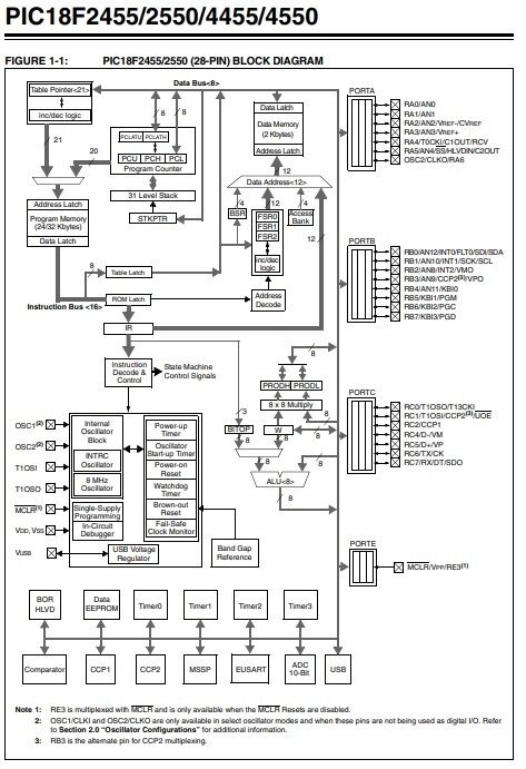
- Architecture
Anmerkungen:
- PIC microcontrollers are based on a Harvard architecture with separate program and data memory. They typically use an 8-bit or 16-bit microcontroller core, but more advanced versions with 32-bit cores are also available.
- Peripherals
Anmerkungen:
- PIC microcontrollers come with a wide range of built-in peripherals such as timers, UART (Universal Asynchronous Receiver-Transmitter), SPI (Serial Peripheral Interface), I2C (Inter-Integrated Circuit), PWM (Pulse Width Modulation), and more. These peripherals make it easier to interface with various sensors and devices.
- Memory
Anmerkungen:
- PIC microcontrollers typically have Flash memory for program storage and SRAM or EEPROM for data storage. The amount of memory can vary depending on the specific model.
- Low Power
Anmerkungen:
- Many PIC microcontrollers are designed to operate on low power, making them suitable for battery-powered applications.
- Development Tools
Anmerkungen:
- Microchip provides a comprehensive set of development tools, including integrated development environments (IDEs), compilers, and programmers, to simplify the development process.
- Wide Range of Models
- Peripheral Libraries
Anmerkungen:
- Microchip offers libraries and software tools to help developers take advantage of the built-in peripherals, speeding up the development process.
- Support and Community
Anmerkungen:
- Due to their popularity, PIC microcontrollers have a large and active user community. This means that there are many online resources, forums, and tutorials available for developers.
- Cost-Effective
Anmerkungen:
- PIC microcontrollers are often considered cost-effective solutions for various embedded applications, making them a popular choice among hobbyists and professionals alike.
- Industrial and Automotive Use
Anmerkungen:
- PIC microcontrollers find applications in a wide range of industries, including industrial automation, automotive systems, consumer electronics, and more.
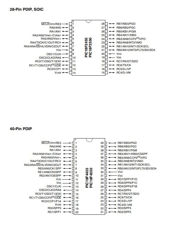
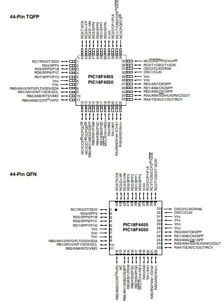
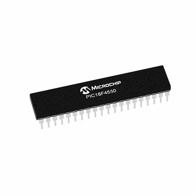
- PIC 18F4550 ports
Anmerkungen:
- A popular microcontroller within the Microchip PIC18 family. It's known for its versatility and a wide range of applications
- USB (Universal Serial Bus) Module
Anmerkungen:
- The USB module allows the PIC18F4550 to function as a USB device, making it suitable for USB-based projects.It supports USB 2.0 Full-Speed (12 Mbps) communication.Common applications include USB communication, HID (Human Interface Device) emulation, USB-to-serial conversion, and more.
- UART (Universal Asynchronous Receiver-Transmitter)
Anmerkungen:
- The PIC18F4550 has one or more UART modules for serial communication.UART is commonly used for communication between the microcontroller and other devices, such as sensors or other microcontrollers.It supports both asynchronous and synchronous serial communication.
- SPI (Serial Peripheral Interface)
Anmerkungen:
- SPI is a synchronous serial communication protocol that allows the microcontroller to communicate with other devices, such as sensors, displays, and other microcontrollers.The PIC18F4550 typically has one or more SPI modules.
- I2C (Inter-Integrated Circuit)
Anmerkungen:
- I2C is another serial communication protocol used for connecting the microcontroller to devices like EEPROMs, real-time clocks (RTC), and sensors.The PIC18F4550 typically has one or more I2C modules.
- Timers
Anmerkungen:
- The PIC18F4550 features multiple timers, including Timer0, Timer1, Timer2, and Timer3, which can be used for various timing and control applications.These timers can generate interrupts and trigger events at specific intervals.
- PWM (Pulse Width Modulation)
Anmerkungen:
- Pulse Width Modulation is used for generating analog-like output signals with varying duty cycles.The PIC18F4550 has PWM modules that are useful for applications like motor control and LED dimming.
- Analog-to-Digital Converter (ADC)
Anmerkungen:
- The ADC module allows the microcontroller to convert analog signals from sensors or external devices into digital values.The PIC18F4550 typically has multiple channels for analog input.
- Comparator
Anmerkungen:
- The comparator module can be used to compare two analog input signals and generate digital outputs based on their relationship.
- Parallel Ports (GPIO)
Anmerkungen:
- The PIC18F4550 has a substantial number of General-Purpose Input/Output (GPIO) pins, which can be configured for various functions.These pins can be used to interface with external components or devices.
- Capture/Compare/PWM (CCP)
Anmerkungen:
- The CCP module can be configured for capturing external events, comparing signals, or generating PWM signals.
- Clock configuration
- Selecting the Clock Source
Anmerkungen:
- The PIC18F4550 can use several clock sources, including the internal oscillator (INTOSC), external crystals, and external clock inputs. To select a clock source, you need to configure the Configuration Bits in the microcontroller.
- Clock Divider Settings
Anmerkungen:
- You can configure the clock divider to further divide the selected clock source frequency. The Clock Divider (also known as the Postscaler) settings are typically available in the microcontroller's Configuration Bits as well
- Initialize Clock in Code
Anmerkungen:
- After configuring the clock source and divider in the Configuration Bits, you need to initialize the clock settings in your code
- Verify Clock Settings
Anmerkungen:
- It's a good practice to verify that the clock settings are correctly configured by reading the relevant status bits.
- Clock sample code
Anmerkungen:
- #include <xc.h> // Clock Configuration void configureClock() { // Configure the internal oscillator to 8 MHz (HFINTOSC) OSCCON = 0b01110000; // Bits 7-6: IRCF<1:0> = 11 (8 MHz frequency) // Bit 5: SCS = 0 (Select internal oscillator) // Wait until the internal oscillator stabilizes while (!OSCCONbits.IOFS); // Wait until the IOFS bit is set } int main() { // Configure the clock configureClock(); // The rest of your program here while (1) { // Main loop } return 0; }
- Selecting the Clock Source
- Ports set up
- Libraries
- Configure Pin Direction
- Write to the Ports
- Read from the Ports
- Manipulate Individual Bits
- Configure Pull-Up/Pull-Down Resistors
- Libraries
Medienanhänge
Möchten Sie kostenlos Ihre eigenen Mindmaps mit GoConqr erstellen? Mehr erfahren.