5014520
Description
Flashcards by John Dedios, updated more than 1 year ago
|
|
Created by John Dedios
about 8 years ago
|
|
| Question | Answer |
| A VLAN creates a logical broadcast domain that can span multiple physical LAN segments. VLANs improve network performance by separating large broadcast domains into smaller ones. If a device in one VLAN sends a broadcast Ethernet frame, all devices in the VLAN receive the frame, but devices in other VLANs do not | VLANs enable the implementation of access and security policies according to specific groupings of users. Each switch port can be assigned to only one VLAN (with the exception of a port connected to an IP phone or to another switch). |
| The primary benefits of using VLANs are as follows: * Security - Groups that have sensitive data are separated from the rest of the network, decreasing the chances of confidential information breaches. * Cost reduction - Cost savings result from reduced need for expensive network upgrades and more efficient use of existing bandwidth and uplinks * Better performance - Dividing flat Layer 2 networks into multiple logical workgroups (broadcast domains) reduces unnecessary traffic on the network and boosts performance | * Shrink broadcast domains - Dividing a network into VLANs reduces the number of devices in the broadcast domain. * Improved IT staff efficiency - VLANs make it easier to manage the network because users with similar network requirements share the same VLAN. * Simpler project and application management - -Having separate functions makes managing a project or working with a specialized application easier |
| 1. Data VLAN - is common practice to separate voice and management traffic from data traffic. A data VLAN is sometimes referred to as a user VLAN. Data VLANs are used to separate the network into groups of users or devices. 4. A management VLAN - is any VLAN configured to access the management capabilities of a switch. VLAN 1 is the management VLAN by default | 2. Default VLAN All switch ports become a part of the default VLAN after the initial boot up of a switch loading the default configuration. Switch ports that participate in the default VLAN are part of the same broadcast domain. This allows any device connected to any switch port to communicate with other devices on other switch ports. The default VLAN for Cisco switches is VLAN 1 |
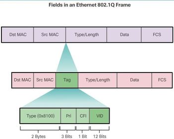
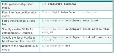
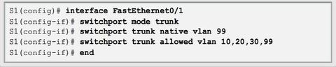
| 3. A native VLAN is assigned to an 802.1Q trunk port. Trunk ports are the links between switches that support the transmission of traffic associated with more than one VLAN. An 802.1Q trunk port supports traffic coming from many VLANs (tagged traffic), as well as traffic that does not come from a VLAN (untagged traffic) | Tagged traffic refers to traffic that has a 4-byte tag inserted within the original Ethernet frame header, specifying the VLAN to which the frame belongs. The 802.1Q trunk port places untagged traffic on the native VLAN, which by default is VLAN 1. |
| VLAN 1 * All ports assigned to VLAN 1 to forward data by default. * Native VLAN is VLAN 1 by default. * Management VLAN is VLAN 1 by default. * VLAN 1 cannot be renamed or deleted. | |
| A separate VLAN is needed to support Voice over IP (VoIP). VoIP traffic requires: * Assured bandwidth to ensure voice quality * Transmission priority over other types of network traffic * Ability to be routed around congested areas on the network * Delay of less than 150 ms across the network | |
| A VLAN trunk extends VLANs across an entire network. Cisco supports IEEE 802.1Q for coordinating trunks on Fast Ethernet, Gigabit Ethernet, and 10-Gigabit Ethernet interfaces. VLAN trunks allow all VLAN traffic to propagate between switches, so that devices which are in the same VLAN, but connected to different switches, can communicate without the intervention of a router. | A VLAN trunk does not belong to a specific VLAN; rather, it is a conduit for multiple VLANs between switches and routers. A trunk could also be used between a network device and server or other device that is equipped with an appropriate 802.1Q-capable NIC. By default, on a Cisco Catalyst switch, all VLANs are supported on a trunk port |
| The 802.1Q header includes a 4-byte tag inserted within the original Ethernet frame header, specifying the VLAN to which the frame belongs. When the switch receives a frame on a port configured in access mode and assigned a VLAN, the switch inserts a VLAN tag in the frame header, recalculates the FCS, and sends the tagged frame out of a trunk port. | |
| 802.1Q header- VLAN Tag Field Details * Type - A 2-byte value called the tag protocol ID (TPID) value. For Ethernet, it is set to hexadecimal 0x8100. * User priority - A 3-bit value that supports level or service implementation. * Canonical Format Identifier (CFI) - A 1-bit identifier that enables Token Ring frames to be carried across Ethernet links. * VLAN ID (VID) - A 12-bit VLAN identification number that supports up to 4096 VLAN IDs. | |
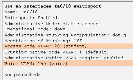
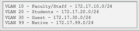
| When configuring an 802.1Q trunk port, a default Port VLAN ID (PVID) is assigned the value of the native VLAN ID. All untagged traffic coming in or out of the 802.1Q port is forwarded based on the PVID value. | For example, if VLAN 99 is configured as the native VLAN, the PVID is 99 and all untagged traffic is forwarded to VLAN 99. If the native VLAN has not been reconfigured, the PVID value is set to VLAN 1. |
| The Cisco IP Phone contains an integrated three-port 10/100 switch. The ports provide dedicated connections to these devices: * Port 1 connects to the switch or other VoIP device. * Port 2 is an internal 10/100 interface that carries the IP phone traffic. * Port 3 (access port) connects to a PC or other device. | |
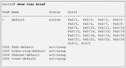
| The number of supported VLANs is large enough to accommodate the needs of most organizations. For example, the Catalyst 2960 and 3560 Series switches support over 4,000 VLANs. Normal range VLANs on these switches are numbered 1 to 1,005 and extended range VLANs are numbered 1,006 to 4,094 | |
| Normal Range VLANs * Used in small- and medium-sized business and enterprise networks. * Identified by a VLAN ID between 1 and 1005. * IDs 1002 through 1005 are reserved for Token Ring and FDDI VLANs. | * IDs 1 and 1002 to 1005 are automatically created and cannot be removed. * Configurations are stored within a VLAN database file, called vlan.dat. The vlan.dat file is located in the flash memory of the switch. * The VLAN Trunking Protocol (VTP), which helps manage VLAN configurations between switches, can only learn and store normal range VLANs. |
| Extended Range VLANs * Enable service providers to extend their infrastructure to a greater number of customers. Some global enterprises could be large enough to need extended range VLAN IDs. * Are identified by a VLAN ID between 1006 and 4094. * Configurations are not written to the vlan.dat file. | * Support fewer VLAN features than normal range VLANs. * Are, by default, saved in the running configuration file. * VTP does not learn extended range VLANs. Note: 4096 is the upper boundary for the number of VLANs available on Catalyst switches, because there are 12 bits in the VLAN ID field of the IEEE 802.1Q header. |
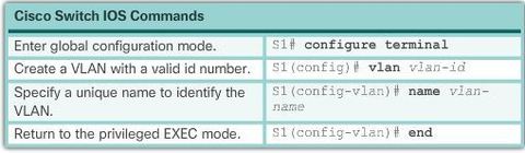
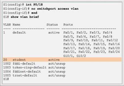
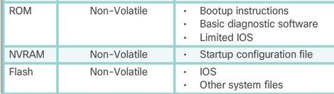
| When configuring normal range VLANs, the configuration details are stored in flash memory on the switch in a file called vlan.dat. Flash memory is persistent and does not require the "copy running-config startup-config" command. use the following command to create VLANs 100, 102, 105, 106, and 107: "S1(config)# vlan 100, 102, 105-107 " | |
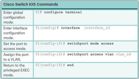
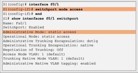
| The "switchport mode access" command is optional, but strongly recommended as a security best practice. With this command, the interface changes to permanent access mode. The "switchport access" vlan command forces the creation of a VLAN if it does not already exist on the switch. For example, VLAN 30 is not present in the "show vlan brief" output of the switch. If the "switchport access vlan 30" command is entered on any interface with no previous configuration, then the switch displays the following: % Access VLAN does not exist. Creating vlan 30 | |
| Caution: Before deleting a VLAN, be sure to first reassign all member ports to a different VLAN. Any ports that are not moved to an active VLAN are unable to communicate with other hosts after the VLAN is deleted and until they are assigned to an active VLAN. Note: For a Catalyst switch, the "erase startup-config" command must accompany the "delete vlan.dat" command prior to reload to restore the switch to its factory default condition. | Alternatively, the entire vlan.dat file can be deleted using the "delete flash:vlan.dat" privileged EXEC mode command. The abbreviated command version "(delete vlan.dat)" can be used if the vlan.dat file has not been moved from its default location. After issuing this command and reloading the switch, the previously configured VLANs are no longer present. This effectively places the switch into its factory default condition concerning VLAN configurations. |
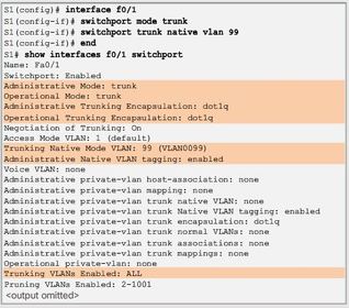
| With this command, the interface changes to permanent trunking mode. The port enters into a Dynamic Trunking Protocol (DTP) negotiation to convert the link into a trunk link even if the interface connecting to it does not agree to the change Note: This configuration assumes the use of Cisco Catalyst 2960 switches which automatically use 802.1Q encapsulation on trunk links. Other switches may require manual configuration of the encapsulation. Always configure both ends of a trunk link with the same native VLAN. If 802.1Q trunk configuration is not the same on both ends, Cisco IOS Software reports errors. | |
| Verifying Trunk Configuration | |
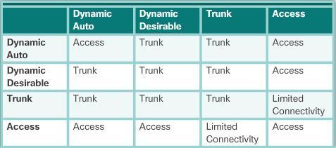
| Trunk negotiation - is managed by the Dynamic Trunking Protocol (DTP), Which operates on a point-to-point basis only, between network devices. DTP is a Cisco proprietary protocol that is automatically enabled on Catalyst 2960 and Catalyst 3560 Series switche DTP manages trunk negotiation only if the port on the neighbor switch is configured in a trunk mode that supports DTP. | ** Caution: Some internetworking devices might forward DTP frames improperly, which can cause misconfigurations. To avoid this, turn off DTP on interfaces on a Cisco switch connected to devices that do not support DTP To enable trunking from a Cisco switch to a device that does not support DTP, use the switchport mode trunk and switchport nonegotiate interface configuration mode commands. This causes the interface to become a trunk, but not generate DTP frames. |
| * Switchport mode access Puts the interface (access port) into permanent nontrunking mode and negotiates to convert the link into a nontrunk link. The interface becomes a nontrunk interface, regardless of whether the neighboring interface is a trunk interface. | |
| * switchport mode dynamic auto - Makes the interface able to convert the link to a trunk link. The interface becomes a trunk interface if the neighboring interface is set to trunk or desirable mode. The default switchport mode for all Ethernet interfaces is "dynamic auto" | * switchport mode dynamic desirable - Makes the interface actively attempt to convert the link to a trunk link. The interface becomes a trunk interface if the neighboring interface is set to trunk, desirable, or auto mode. This is the default switchport mode on older switches, such as the Catalyst 2950 and 3550 Series switches. |
| * switchport mode trunk Puts the interface into permanent trunking mode and negotiates to convert the neighboring link into a trunk link. The interface becomes a trunk interface even if the neighboring interface is not a trunk interface. | * switchport nonegotiate Prevents the interface from generating DTP frames. You can use this command only when the interface switchport mode is access or trunk. You must manually configure the neighboring interface as a trunk interface to establish a trunk link. |
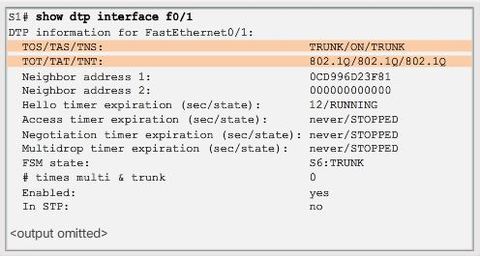
| To determine the current DTP mode, issue the "show dtp interface" command * Note: A general best practice is to set the interface to trunk and nonegotiate when a trunk link is required. On links where trunking is not intended, DTP should be turned off. | |
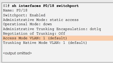
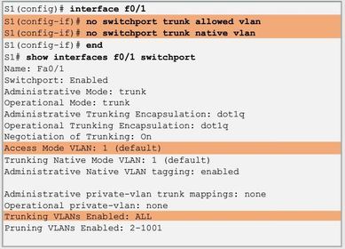
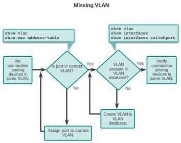
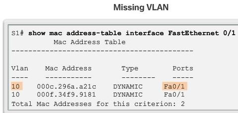
| Step 1. Use the show vlan command to check whether the port belongs to the expected VLAN. If the port is assigned to the wrong VLAN, use the switchport access vlan command to correct the VLAN membership. Use the show mac address-table command to check which addresses were learned on a particular port of the switch and to which VLAN that port is assigned. Step 2. If the VLAN to which the port is assigned is deleted, the port becomes inactive. Use the show vlan or show interfaces switchport command. | |
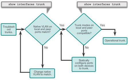
| Troubleshooting Trunks Step 1. Use the show interfaces trunk command to check whether the local and peer native VLANs match. If the native VLAN does not match on both sides, VLAN leaking occurs. Step 2. Use the show interfaces trunk command to check whether a trunk has been established between switches. Statically configure trunk links whenever possible. Cisco Catalyst switch ports use DTP by default and attempt to negotiate a trunk link. | |
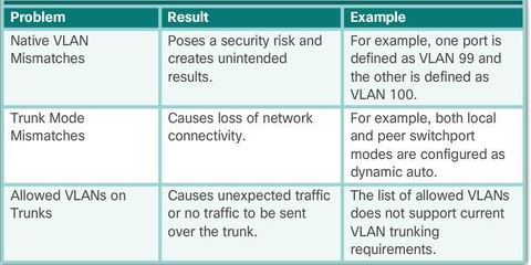
| CDP displays a notification of a native VLAN mismatch on a trunk link with this message: *Mar 1 06:45:26.232: %CDP-4-NATIVE_VLAN_MISMATCH: Native VLAN mismatch discovered on FastEthernet0/1 (2), with S2 FastEthernet0/1 (99). | Connectivity issues occur in the network if a native VLAN mismatch exists. Data traffic for VLANs, other than the two native VLANs configured, successfully propagates across the trunk link, but data associated with either of the native VLANs does not successfully propagate across the trunk link. |
| If an issue with a trunk is discovered and if the cause is unknown, start troubleshooting by examining the trunks for a native VLAN mismatch. If that is not the cause, check for trunk mode mismatches, and finally check for the allowed VLAN list on the trunk | |
| Trunk Mode Mismatches Examining the F0/3 interface reveals that the switch port is actually in dynamic auto mode. An examination of the trunks on switch S3 reveals that there are no active trunk ports. Further checking reveals that the Fa0/3 interface is also in dynamic auto mode. This explains why the trunk is down. To resolve the issue, reconfigure the trunk mode of the F0/3 ports on switches S1 and S3 | |
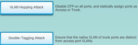
| . Switch spoofing is a type of VLAN hopping attack that works by taking advantage of an incorrectly configured trunk port. By default, trunk ports have access to all VLANs and pass traffic for multiple VLANs across the same physical link, generally between switches In a basic switch spoofing attack, the attacker takes advantage of the fact that the default configuration of the switch port is dynamic auto. The network attacker configures a system to spoof itself as a switch. | This spoofing requires that the network attacker be capable of emulating 802.1Q and DTP messages. By tricking a switch into thinking that another switch is attempting to form a trunk, an attacker can gain access to all the VLANs allowed on the trunk port. The best way to prevent a basic switch spoofing attack is to turn off trunking on all ports, except the ones that specifically require trunking. On the required trunking ports, disable DTP, and manually enable trunking. |
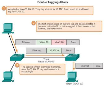
| This tag allows the frame to be forwarded to a VLAN that the original 802.1Q tag did not specify. An important characteristic of the double-encapsulated VLAN hopping attack is that it works even if trunk ports are disabled, because a host typically sends a frame on a segment that is not a trunk link. The best approach to mitigating double-tagging attacks is to ensure that the native VLAN of the trunk ports is different from the VLAN of any user ports | |
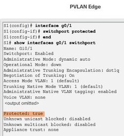
| The PVLAN Edge feature has the following characteristics: * A protected port does not forward any traffic (unicast, multicast, or broadcast) to any other port that is also a protected port, except for control traffic. Data traffic cannot be forwarded between protected ports at Layer 2. * Forwarding behavior between a protected port and a nonprotected port proceeds as usual. * Protected ports must be manually configured. | |
| There are many key structures and performance-related characteristics referred to when discussing networks: * Topology - There are physical and logical topologies. * Speed - Speed is a measure of the data rate in bits per second (b/s) of a given link in the network. * Cost - Cost indicates the general expense for purchasing of network components, and installation and maintenance of the network. * Security - Security indicates how protected the network is, including the information that is transmitted over the network. | * Availability - Availability is a measure of the probability that the network is available for use when it is required. * Scalability - Scalability indicates how easily the network can accommodate more users and data transmission requirements. * Reliability - Reliability indicates the dependability of the components that make up the network, such as the routers, switches, PCs, and servers. Reliability is often measured as a probability of failure or as the mean time between failures (MTBF). |
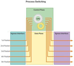
| * Process switching - An older packet forwarding mechanism still available for Cisco routers. When a packet arrives on an interface, it is forwarded to the control plane where the CPU matches the destination address with an entry in its routing table, and then determines the exit interface and forwards the packet. It is important to understand that the router does this for every packet, even if the destination is the same for a stream of packets. This process-switching mechanism is very slow and rarely implemented in modern networks | |
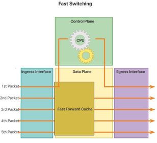
| * Fast switching - This is a common packet forwarding mechanism which uses a fast-switching cache to store next-hop information. When a packet arrives on an interface, it is forwarded to the control plane where the CPU searches for a match in the fast-switching cache. If it is not there, it is process-switched and forwarded to the exit interface | |
| * Cisco Express Forwarding (CEF) - Like fast switching, CEF builds a Forwarding Information Base (FIB), and an adjacency table. However, the table entries are not packet-triggered like fast switching but change-triggered such as when something changes in the network topology. Therefore, when a network has converged, the FIB and adjacency tables contain all the information a router would have to consider when forwarding a packet. The FIB contains pre-computed reverse lookups, next hop information for routes including the interface and Layer 2 information. Cisco Express Forwarding is the fastest forwarding mechanism and the preferred choice on Cisco routers. | |
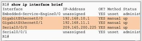
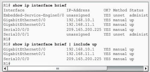
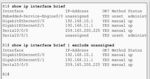
| "show ip interface brief" - Displays a summary for all interfaces including the IPv4 address of the interface and current operational status. Note: In Figure 1, the Embedded-Service-Engine0/0 interface is displayed because Cisco ISRs G2 have dual core CPUs on the motherboard. " show ip interface" - Displays the IPv4 related information for all interfaces on a router. | |
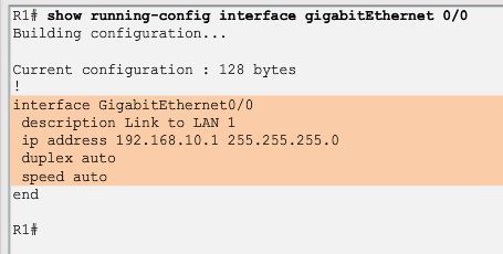
| " show running-config interface (interface-id) " Displays the commands configured on the specified interface. "show interfaces " Displays interface information and packet flow count for all interfaces on the device. | |
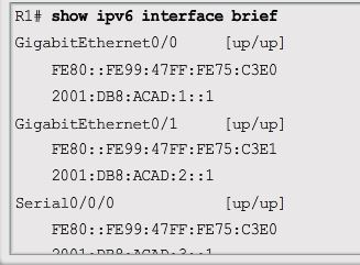
| The "show ipv6 interface brief" command in Figure 1 displays a summary for each of the interfaces. The [up/up] output on the same line as the interface name indicates the Layer 1/Layer 2 interface state. This is the same as the Status and Protocol columns in the equivalent IPv4 command. The other address, which begins with FE80, is the link-local unicast address for the interface | |
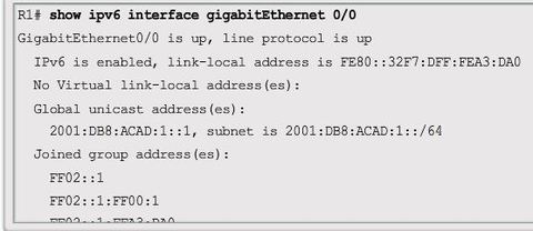
| The "show ipv6 interface gigabitethernet 0/0" command output shown in Figure 2 displays the interface status and all of the IPv6 addresses belonging to the interface. Along with the link local address and global unicast address, the output includes the multicast addresses assigned to the interface, beginning with prefix FF02. | |
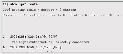
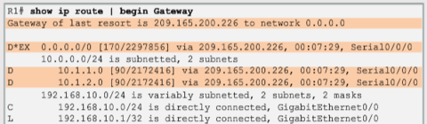
| The "show ipv6 route" command shown in Figure 3 can be used to verify that IPv6 networks and specific IPv6 interface addresses have been installed in the IPv6 routing table. Other useful IPv6 verification commands include: " show interface " " show ipv6 routers " | |
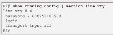
| Filtering commands can be used to display specific sections of output. To enable the filtering command, enter a pipe (|) character after the show command and then enter a filtering parameter and a filtering expression. * section - Shows entire section that starts with the filtering expression | |
| " include " Includes all output lines that match the filtering expression | |
| "exclude " Excludes all output lines that match the filtering expression | |
| "begin" Shows all the output lines from a certain point, starting with the line that matches the filtering expression | |
| "begin" Shows all the output lines from a certain point, starting with the line that matches the filtering expression | |
| Router Switching Function A key responsibility of the switching function is to encapsulate packets in the appropriate data link frame type for the outgoing data link. Note: In this context, the term “switching” literally means moving packets from source to destination and should not be confused with the function of a Layer 2 switch. After the router has determined the exit interface using the path determination function, the router must encapsulate the packet into the data link frame of the outgoing interface. | What does a router do with a packet received from one network and destined for another network? The router performs the following three major steps: Step 1. De-encapsulates the Layer 2 frame header and trailer to expose the Layer 3 packet. Step 2. Examines the destination IP address of the IP packet to find the best path in the routing table. Step 3. If the router finds a path to the destination, it encapsulates the Layer 3 packet into a new Layer 2 frame and forwards the frame out the exit interface. |
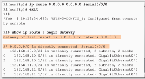
| "No route determined" If the destination IP address of the packet does not belong to either a connected or remote network, the router determines if there is a Gateway of Last Resort available. A Gateway of Last Resort is set when a default route is configured on a router. If there is a default route, the packet is forwarded to the Gateway of Last Resort. If the router does not have a default route, then the packet is discarded. | |
| Best Path * Routing Information Protocol (RIP) - Hop count | * Open Shortest Path First (OSPF) - Cisco’s cost based on cumulative bandwidth from source to destination ** Enhanced Interior Gateway Routing Protocol (EIGRP) - Bandwidth, delay, load, reliability |
| When a router has two or more paths to a destination with equal cost metrics, then the router forwards the packets using both paths equally. This is called equal cost load balancing. The routing table contains the single destination network, but has multiple exit interfaces, one for each equal cost path. The router forwards packets using the multiple exit interfaces listed in the routing table. | If configured correctly, load balancing can increase the effectiveness and performance of the network. Equal cost load balancing can be configured to use both dynamic routing protocols and static routes. Note: Only EIGRP supports unequal cost load balancing. |
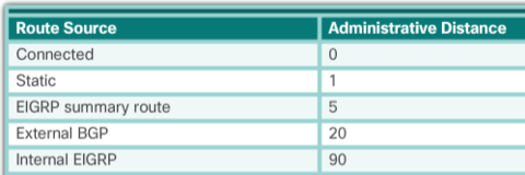
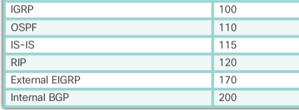
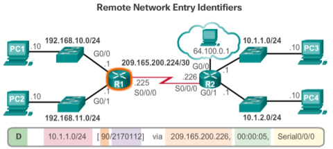
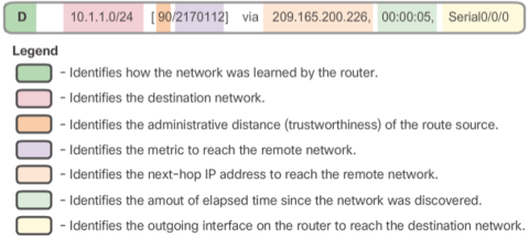
| Cisco IOS uses what is known as the administrative distance (AD) to determine the route to install into the IP routing table. The AD represents the "trustworthiness" of the route; the lower the AD, the more trustworthy the route source. For example, a static route has an AD of 1, whereas an EIGRP-discovered route has an AD of 90. | Given two separate routes to the same destination, the router chooses the route with the lowest AD. When a router has the choice of a static route and an EIGRP route, the static route takes precedence. Similarly, a directly connected route with an AD of 0 takes precedence over a static route with an AD of 1. |
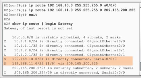
| The sources of the routing table entries are identified by a code. The code identifies how the route was learned. For instance, common codes include: * L - Identifies the address assigned to a router’s interface. This allows the router to efficiently determine when it receives a packet for the interface instead of being forwarded. * C - Identifies a directly connected network. | * S - Identifies a static route created to reach a specific network. * D - Identifies a dynamically learned network from another router using EIGRP. * O - Identifies a dynamically learned network from another router using the OSPF routing protocol. |
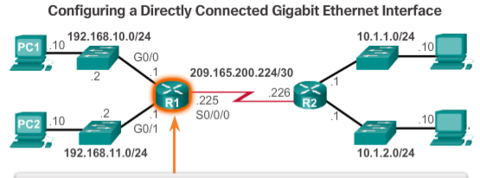
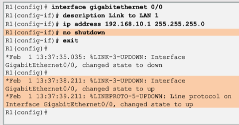
| Before the interface state is considered up/up and added to the IPv4 routing table, the interface must: * Be assigned a valid IPv4 or IPv6 address | * Be activated with the "no shutdown" command * Receive a carrier signal from another device (router, switch, host, etc.) |
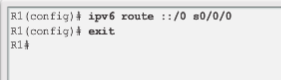
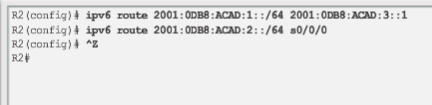
| The benefits of using static routes include improved security and resource efficiency. Static routes use less bandwidth than dynamic routing protocols, and no CPU cycles are used to calculate and communicate routes. The main disadvantage to using static routes is the lack of automatic reconfiguration if the network topology changes. There are two common types of static routes in the routing table: 1. Static route to a specific network 2. Default static route | IPv4 static routes are configured using the: "ip route network mask {next-hop-ip | exit-intf}" global configuration command To configure an IPv4 default static route, use the: " ip route 0.0.0.0 0.0.0.0 {exit-intf | next-hop-ip}" global configuration command. |
| The entry beginning with ‘D*EX’ identifies that the source of this entry was EIGRP (‘D’). The route is a candidate to be a default route (‘*’), and the route is an external route (‘*EX’) forwarded by EIGRP. The other two ‘D’ entries are routes installed in the routing table based on the update from R2 advertising its LANs. | |
Want to create your own Flashcards for free with GoConqr? Learn more.