5941204
Description
Flashcards by John Dedios, updated more than 1 year ago
|
|
Created by John Dedios
over 7 years ago
|
|
| Question | Answer |
| Benefits of Wireless ** Some of the benefits include increased flexibility, increased productivity, reduced costs, and the ability to grow and adapt to changing requirements. Wireless networks can be classified broadly as: * Wireless Personal-Area Networks (WPAN) - Operates in the range of a few feet. Bluetooth or Wi-Fi Direct-enabled devices are used in WPANs | * Wireless LANs (WLANs) - Operates in the range of a few hundred feet such as in a room, home, office, and even campus environment. * Wireless Wide-Area Networks (WWANs) - Operates in the range of miles such as a metropolitan area, cellular hierarchy, or even on intercity links through microwave relays. |
| Bluetooth Originally an IEEE 802.15 WPAN standard that uses a device-pairing process to communicate over distances up to .05 mile (100m). * Supports speeds of up to 24 Mb/s (Bluetooth v3). * Supports three different power ranges: 100 meters (long range). 10 meters (ordinary range). 10 cm (short range). | Wi-Fi (wireless fidelity) - An IEEE 802.11 WLAN standard commonly deployed to provide network access to home and corporate users, to distances up to 300m (0.18 mile). ** Variations include 802.11a/b/g/n/ac/ad. * Speeds vary based on technology. |
| WiMAX (Worldwide Interoperability for Microwave Access) An IEEE 802.16 WWAN standard that provides wireless broadband access of up to 30 miles (50 km). * Uses a point-to-multipoint topology to provide wireless cellular broadband access. * Used as an alternative to cable and DSL. * Supports speeds up to 1 Gb/s. | Satellite broadband Provides network access to remote sites through the use of a directional satellite dish that is aligned with a specific geostationary Earth orbit (GEO) satellite. * Expensive, but ideal in situations such as remote areas where no other wireless access is available. * Supports download speeds up to 10 Mb/s and higher, depending on satellite provider infrastructure. |
| Cellular broadband Consists of various corporate, national, and international organizations using service provider cellular access to provide mobile broadband network connectivity. First available with 2nd generation cell phones in 1991 (2G) with higher speeds becoming available in 2001 and 2006 as part of the third (3G) and fourth (4G) generations of mobile communication technology. | * Cellular broadband access consisting of various standards supporting download speeds up to 5 Mb/s and higher, depending on wireless provider infrastructure. ** Variations include 2G (using GSM, CDMA, or TDMA), 3G (using UMTS, CDMA2000, EDGE, or HSPA+) and 4G (using WiMAX or LTE). |
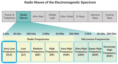
| Radio Frequencies It is the responsibility of the International Telecommunication Union - Radiocommunication Sector (ITU-R) to regulate the allocation of the radio frequency (RF) spectrum. Ranges of frequencies, called bands, are allocated for various purposes. * Other bands are license free, such as the Industrial, Scientific, and Medical (ISM) and the unlicensed national information infrastructure (UNII) frequency bands. | |
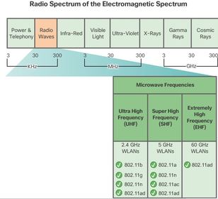
| Radio Frequencies Note: WLAN networks operate in the ISM 2.4 GHz frequency band and the UNII 5 GHz band. Wireless communication occurs in the radio waves range (i.e., 3 Hz to 300 GHz) of the electromagnetic spectrum. ** The radio waves range is subdivided into a radio frequencies section and a microwave frequencies section. Notice that WLANs, Bluetooth, cellular, and satellite communication all operate in the microwave UHF, SHF, and EHF ranges. | Wireless LAN devices have transmitters and receivers tuned to specific frequencies of the radio waves range. Specifically, the following frequency bands are allocated to 802.11 wireless LANs: * 2.4 GHz (UHF) - 802.11b/g/n/ad * 5 GHz (SHF) - 802.11a/n/ac/ad * 60 GHz (EHF) - 802.11ad |
| 802.11 Standards The IEEE 802.11 WLAN standard defines how RF in the unlicensed ISM frequency bands is used for the physical layer and the MAC sublayer of wireless links. | |
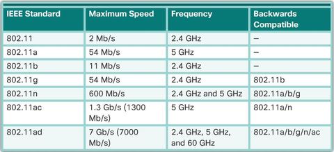
| * 802.11 - Released in 1997 and now obsolete, this is the original WLAN specification. ** IEEE 802.11a - Released in 1999. Because this standard operates at higher frequencies, it has a smaller coverage area and is less effective at penetrating building structures. * IEEE 802.11b - Released in 1999Devices implementing this standard have a longer range and are better able to penetrate building structures than devices based on 802.11a. ** IEEE 802.11g - Released in 2003,t is backward compatible with 802.11b. However, when supporting an 802.11b client, the overall bandwidth is reduced. | * IEEE 802.11n - Released in 2009,Typical data rates range from 150 Mb/s to 600 Mb/s with a distance range of up to 70 m (.5 mile) ** APs and wireless clients require multiple antennas using the multiple-input and multiple-output (MIMO) technology. MIMO use multiple antennas as both the transmitter and receiver to improve communication performance. Up to four antennas can be supported. The 802.11n standard is backward compatible with 802.11a/b/g devices. However supporting a mixed environment limits the expected data rates. |
| ** IEEE 802.11ac - Released in 2013, operates in the 5 GHz frequency band and provides data rates ranging from 450 Mb/s to 1.3 Gb/s (1300 Mb/s). It uses MIMO technology to improve communication performance. Up to eight antennas can be supported. The 802.11ac standard is backward compatible with 802.11a/n devices; however, supporting a mixed environment limits the expected data rates. | ** IEEE 802.11ad - Scheduled for release in 2014 and also known as “WiGig”, it uses a tri-band Wi-Fi solution using 2.4 GHz, 5 GHz, and 60 GHz, and offers theoretical speeds of up to 7 Gb/s. However, the 60 GHz band is a line-of-site technology and; therefore, cannot penetrate through walls. When a user is roaming, the device switches to the lower 2.4 GHz and 5 GHz bands. It is backward compatible with existing Wi-Fi devices. However supporting a mixed environment limits the expected data rates. |
| Wi-Fi Certification * IEEE - Specifies how RF is modulated to carry information. It maintains the standards for local and metropolitan area networks (MAN) with the IEEE 802 LAN/MAN family of standards. The dominant standards in the IEEE 802 family are 802.3 Ethernet and 802.11 WLAN. Although the IEEE has specified standards for RF modulation devices, it has not specified manufacturing standards; therefore, interpretations of the 802.11 standards by different vendors can cause interoperability problems between their devices. | * Wi-Fi Alliance - The Wi-Fi Alliance® (http://www.wi-fi.org) is a global, non-profit, industry trade association devoted to promoting the growth and acceptance of WLANs. It is an association of vendors whose objective is to improve the interoperability of products that are based on the 802.11 standard by certifying vendors for conformance to industry norms and adherence to standards. * ITU-R - Regulates the allocation of the RF spectrum and satellite orbits. |
| The Wi-Fi Alliance certifies Wi-Fi and the following product compatibility: * IEEE 802.11a/b/g/n/ac/ad compatible * IEEE 802.11i secure using WPA2™ and Extensible Authentication Protocol (EAP) * Wi-Fi Protected Setup (WPS) to simplify device connections | * Wi-Fi Direct to share media between devices * Wi-Fi Passpoint to simplify securely connecting to Wi-Fi hotspot networks * Wi-Fi Miracast to seamlessly display video between devices ** Note: Other Wi-Fi certifications products are available such as WMM® (Wi-Fi Multimedia™), Tunneled Direct Link Setup (TDLS), and WMM-Power Save. |
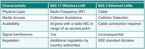
| Comparing WLANs to a LAN The IEEE has adopted the 802 LAN/MAN portfolio of computer network architecture standards. The two dominant 802 working groups are 802.3 Ethernet and 802.11 WLAN. * WLANs support hosts that contend for access on the RF media (frequency bands). 802.11 prescribes collision-avoidance (CSMA/CA) instead of collision-detection (CSMA/CD) for media access to proactively avoid collisions within the media. | |
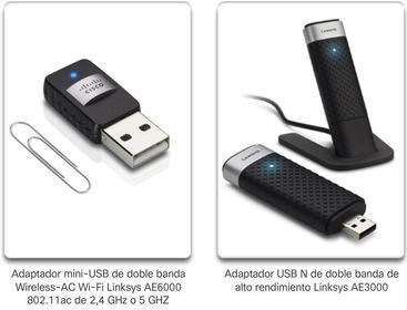
| Wireless NICs The simplest wireless network requires a minimum of two devices. Each device must have a radio transmitter and a radio receiver tuned to the same frequencies. However most wireless deployments require: * End devices with wireless NICs * Infrastructure device, such as a wireless router or wireless AP | |
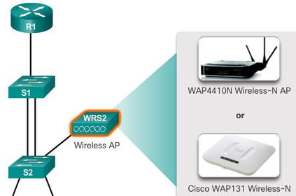
| Business Wireless Solutions Note: IEEE 802.11 refers to a wireless client as a station (STA) * Wireless clients use their wireless NIC to discover nearby APs advertisingits services by sending beacons containing its shared service set identifier (SSID). Clients then attempt to associate and authenticate with an AP, After being authenticated, wireless users have access to network resources. | |
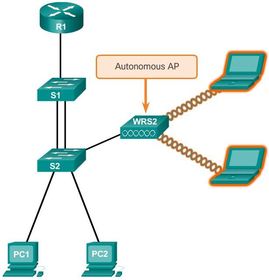
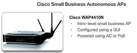
| Wireless Access Points 1.- Autonomous Aps - sometimes referred to as heavy APs, are standalone devices configured using the Cisco CLI or a GUI. Autonomous APs are useful in situations where only a couple of APs are required in the network. ** Optionally, multiple APs can be controlled using wireless domain services (WDS) and managed using CiscoWorks Wireless LAN Solution Engine (WLSE). Note: A home router is an example of an autonomous AP because the entire AP configuration resides on the device. | |
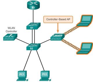
| Wireless Access Points 2. Controller-based APs - are server-dependent devices that require no initial configuration. Cisco offers two controller-based solutions. Controller-based APs are useful in situations where many APs are required in the network. As more APs are added, each AP is automatically configured and managed by a WLAN controller. * Note: Some AP models can operate in either autonomous mode or in controller-based mode. | |
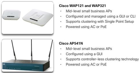
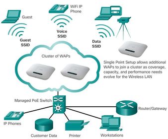
| Small Wireless Deployment Solutions ** the WAP121, WAP321, and AP541N APs support the clustering of APs without the use of a controller. The cluster provides a single point of administration and enables the administrator to view the deployment of APs as a single wireless network, rather than a series of separate wireless devices. ** The clustering capability makes it easy to set up, configure, and manage a growing wireless network. Multiple APs can be deployed and push a single configuration to all the devices within the cluster, managing the wireless network as a single system without worrying about interference between APs, and without configuring each AP as a separate device. | A cluster can be formed between two APs if the following conditions are met: * Clustering mode is enabled on the APs. * The APs joining the cluster have the same Cluster Name. * The APs are connected on the same network segment. * The APs use the same radio mode (i.e., both radios use 802.11n.) |
| Small Wireless Deployment Solutions * Specifically, the WAP121 and WAP321 support Single Point Setup (SPS), which makes AP deployment easier and faster. Ej: SPS helps to enable the wireless LAN to scale up to four WAP121 and up to eight WAP321 devices to provide broader coverage and support additional users as business needs change and grow. The Cisco AP541N AP can cluster up to 10 APs together and can support multiple clusters. | |
| Large Wireless Deployment Solutions For larger organizations with many APs, Cisco provides controller-based managed solutions, including the Cisco Meraki Cloud Managed Architecture and the Cisco Unified Wireless Network Architecture. Note: There are other controller-based solutions, such as the controllers using Flex mode. Visit http://www.cisco.com for more information. | ** The Cisco Meraki cloud architecture is a management solution used to simplify the wireless deployment. Using this architecture, APs are managed centrally from a controller in the cloud, Cloud networking and management provides centralized management, visibility, and control without the cost and complexity of controller appliances or overlay management software. This process reduces costs and complexity. The controller pushes management settings, such as firmware updates, security settings, wireless network, and SSIDs settings to the Meraki APs |
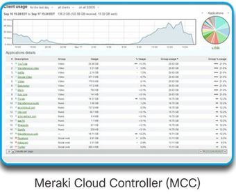
| Large Wireless Deployment Solutions The Cisco Meraki cloud managed architecture requires the following: 1. Cisco MR Cloud Managed Wireless APs - Various models exist to address a broad range of wireless deployment. 3. Web-based Dashboard - Meraki’s web-based Dashboard performs configuration and diagnostics remotely. | 2. Meraki Cloud Controller (MCC) - The MCC provides centralized management, optimization, and monitoring of a Meraki WLAN system. The MCC is not an appliance that must be purchased and installed to manage wireless APs. Rather, the MCC is a cloud-based service that constantly monitors, optimizes, and reports the behavior of the network. |
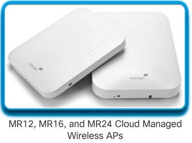
| MR12, MR16 & MR24 * Indoor, cloud managed 802.11n APs. * Self-configuring, plug-and-play deployment. * Self-healing, zero-configuration mesh. * The MR12 is for teleworker environments while the MR24 is for large enterprise deployments. * Cisco recommends using the MR12 for small branches and low-density deployments. The MR16 is recommended for organizations that are mobility-intensive. The MR24 is ideal for performance critical wireless LANs and high-density environments. | |
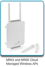
| MR62 & MR66 * 802.11n outdoor access points designed for harsh, rugged environments (IP-67 rated). * Enterprise-grade security with guest access and BYOD support. * Supports external antennas. | |
| Meraki Cloud Controller - MCC * The MCC is a cloud-based service that is constantly monitoring, optimizing, and reporting on the behavior of the network. * The MCC provides centralized management, optimization, and monitoring of a Meraki wireless LAN system. * The two versions of MCC available are the Meraki Enterprise Cloud Controller and Meraki Pro Cloud Controller. * The Meraki Dashboard is the web-based interface to the MCC and provides remote network monitoring and troubleshooting capabilities. | |
| Large Wireless Deployment Solutions, Cont. * The Cisco Unified wireless network architecture solution, using a split MAC design, controls APs using a WLAN controller (WLC) and can be optionally managed using Cisco Wireless Control Systems (WCS). The lightweight APs communicate with the WLAN controller using the Lightweight Access Control Point Protocol (LWAPP). The controller has all of the intelligence for communication and the AP is a “dumb terminal” that simply processes packets. | |
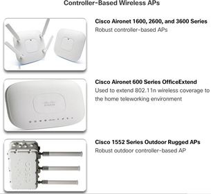
| The Cisco Unified wireless network architecture requires the following devices: * Lightweight APs - Cisco Aironet 1600, 2600, or 3600 wireless APs models provide robust, dependable wireless network access for hosts. * Controllers for small and medium-sized businesses - Cisco 2500 Series Wireless Controllers, Cisco Virtual Wireless Controller, or the Cisco Wireless Controller Module for Cisco ISR G2 provide small branch or single-site enterprise WLAN deployments with entry-level wireless for data. | ** Other WLAN controllers of greater capacity are also available. For example, the Cisco 5760 Wireless Controller and the Cisco 8500 Series Controller are designed to cost-effectively manage, secure, and optimize the performance of sizeable wireless networks, such as service provider and large campus deployments. |
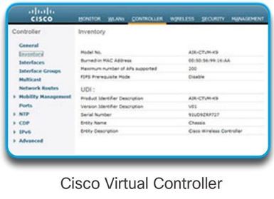
| Cisco Virtual Controller * Deployed on an x86 server that supports VMware ESXi 4.x or 5.x, 1 virtual CPU, 2 GB memory, 8 GB disk space, and 2 or more virtual Network Interface cards (vNICs). * Used to configure, manage, and troubleshoot up to 200 APs and 3000 clients. * Supports secure guest access, rogue detection for PCI compliance. | |
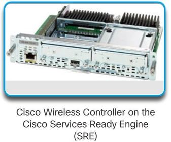
| Cisco Wireless Controller on the Cisco Services Ready Engine (SRE) * Integrated Services Module 300 (ISM-300) supports up to 10 APs. * Cisco Services-Ready Engine Module 710 and 910 (SM-710) and (SM-910) supports up to 50 AP and 500 clients. * PCI functionality for scanner and kiosk support | |
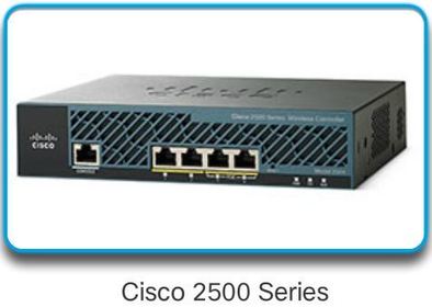
| Cisco 2500 Series * Standalone, small form-factor appliance. * Four 1 Gigabit Ethernet ports (two PoE). * Support up to 75 access points and 1000 clients. * PCI functionality for scanner and kiosk. | |
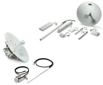
| Wireless Antennas Most business class APs require the use of external antennas to make them fully-functioning units. Cisco has developed antennas specifically designed for use with 802.11 APs while accommodating specific deployment conditions, including physical layout, distance, and aesthetics. Cisco Aironet APs can use: 1. Omnidirectional Wi-Fi Antennas - Factory Wi-Fi gear often uses basic dipole antennas, also referred to as “rubber duck” design, similar to those used on walkie-talkie radios. Omnidirectional antennas provide 360-degree coverage and are ideal in open office areas, hallways, conference rooms, and outside areas. | 2. Directional Wi-Fi Antennas - Directional antennas focus the radio signal in a given direction. This enhances the signal to and from the AP in the direction the antenna is pointing, providing stronger signal strength in one direction and less signal strength in all other directions. 3. Yagi antennas - Type of directional radio antenna that can be used for long-distance Wi-Fi networking. These antennas are typically used to extend the range of outdoor hotspots in a specific direction, or to reach an outbuilding. |
| Wireless Antennas ** IEEE 802.11n/ac/ad use MIMO technology to increase available bandwidth. Specifically, MIMO uses multiple antennas to exchange more data than it would be possible to do using a single antenna. Up to four antennas can be used to increase throughput. * Note: Not all wireless routers are the same. For instance, entry level 802.11n routers support 150 Mb/s bandwidth using one Wi-Fi radio, and one antenna attached to the unit. To support the higher data rates, an 802.11n router requires more radios and antennas to manage more channels of data in parallel. For example, two radios and two antennas on an 802.11n router support up to 300 Mb/s, while 450 and 600 Mb/s require three and four radios and antennas, respectively | |
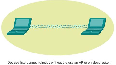
| 802.11 Wireless Topology Modes The 802.11 standard identifies two main wireless topology modes: 1. Ad hoc mode - When two devices connect wirelessly without the aid of an infrastructure device, such as a wireless router or AP. Examples include Bluetooth and Wi-Fi Direct. | |
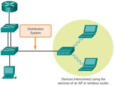
| 802.11 Wireless Topology Modes The 802.11 standard identifies two main wireless topology modes: 2. Infrastructure mode - When wireless clients interconnect via a wireless router or AP, such as in WLANs. APs connect to the network infrastructure using the wired distribution system (DS), such as Ethernet. | |
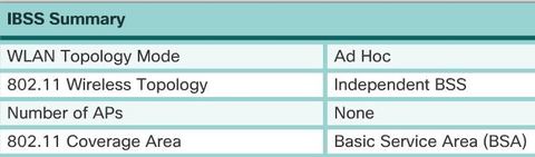
| Ad Hoc Mode * Note: The IEEE 802.11 standard refers to an ad hoc network as an independent basic service set (IBSS). * A variation of the ad hoc topology is when a smart phone or tablet with cellular data access is enabled to create a personal hotspot. This feature is sometimes referred to as: Tethering. | |
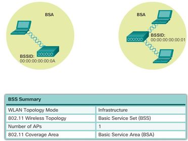
| Infrastructure Mode 1. Basic Service Set A BSS consists of a single AP interconnecting all associated wireless clients. Ej: The circles depict the coverage area within which the wireless clients of the BSS may remain in communication. This area is called the Basic Service Area (BSA). The Layer 2 MAC address of the AP is used to uniquely identify each BSS, which is called the Basic Service Set Identifier (BSSID). Therefore, the BSSID is the formal name of the BSS and is always associated with only one AP. | |
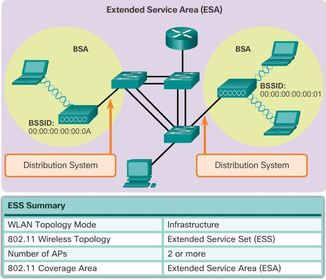
| Infrastructure Mode 2. Extended Service Set - When a single BSS provides insufficient RF coverage, two or more BSSs can be joined through a common distribution system (DS) into an ESS. Ej: an ESS is the union of two or more BSSs interconnected by a wired DS. Wireless clients in one BSA can now communicate with wireless clients in another BSA within the same ESS. Roaming mobile wireless clients may move from one BSA to another (within the same ESS) and seamlessly connect. * Each ESS is identified by an SSID and in an ESS each BSS is identified by its BSSID. For security reasons, additional SSIDs can be propagated through the ESS to segregate the level of network access. | |
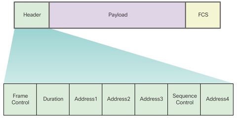
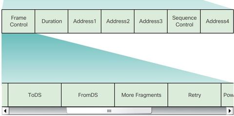
| Wireless 802.11 Frame * Frame Control - Identifies the type of wireless frame and contains subfields for protocol version, frame type, address type, power management, and security settings. * Duration - Typically used to indicate the remaining duration needed to receive the next frame transmission. * Address1 - Usually contains the MAC address of the receiving wireless device or AP. * Address2 - Usually contains the MAC address of the transmitting wireless device or AP. | |
| Wireless 802.11 Frame * Address3 - Sometimes contains the MAC address of the destination, such as the router interface (default gateway) to which the AP is attached. * Sequence Control - Contains the Sequence Number and the Fragment Number subfields. The Sequence Number indicates the sequence number of each frame. The Fragment Number indicates the number of each frame sent of a fragmented frame. * Address4 - Usually missing because it is used only in ad hoc mode. * Payload - Contains the data for transmission. * FCS - Frame Check Sequence; used for Layer 2 error control. | |
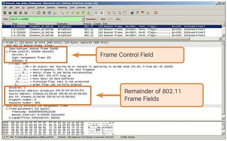
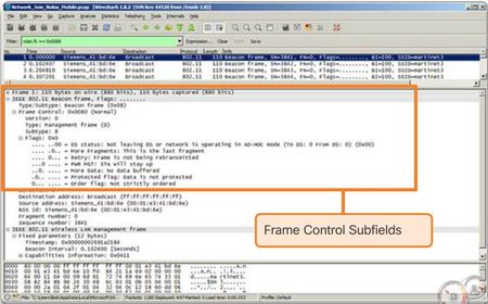
| Wireless 802.11 Frame Ej: displays a Wireshark capture of a WLAN beacon frame. Notice how the Frame Control field has also been expanded to display its subfields. Note: The content of the Address fields vary depending on settings in the Frame Control field. | |
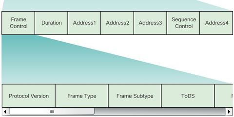
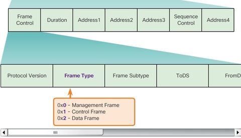
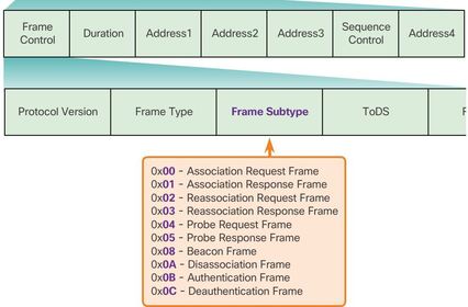
| Frame Control Field 1. Protocol Version - Provides the current version of the 802.11 protocol used. Receiving devices use this value to determine if the version of the protocol of the received frame is supported. 2. & 3. Frame Type and Frame Subtype - Determines the function of the frame. A wireless frame can either be a control frame, data frame, or a management frame. There are multiple subtype fields for each frame type. Each subtype determines the specific function to perform for its associated frame type. | |
| Frame Control Field 4. & 5. ToDS and FromDS - Indicates whether the frame is going to or exiting from the DS, and is only used in data frames of wireless clients associated with an AP. 6. More Fragments - Indicates whether more fragments of the frame, either data or management type, are to follow. 7. Retry - Indicates whether or not the frame, for either data or management frame types, is being retransmitted. | |
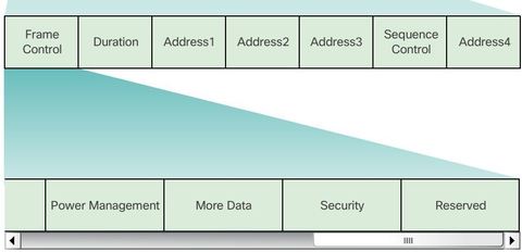
| Frame Control Field 8. Power Management - Indicates whether the sending device is in active mode or power-save mode. 9. More Data - Indicates to a device in power-save mode that the AP has more frames to send. It is also used for APs to indicate that additional broadcast/multicast frames are to follow. 10. Security - Indicates whether encryption and authentication are used in the frame. It can be set for all data frames and management frames, which have the subtype set to authentication. 11. Reserved - Can indicate that all received data frames must be processed in order. | |
| Frame Control Field Ej: displays a Wireshark capture of a WLAN beacon frame. Notice that the Frame Type field and the Frame Subtype fields identify if the frame is a management frame, a control frame, or a data frame. In the example, the Frame Type is ‘0x0’ identifying it as a management frame. The subtype value ‘8’ identifies this as a beacon frame. The frame is specifically identified as ‘0x08’. | |
| Wireless Frame Type Ej: a wireless frame can be one of three frame types: 0X0. Management Frame - Used in the maintenance of communication, such as finding, authenticating, and associating with an AP. 0X1. Control Frame - Used to facilitate in the exchange of data frames between wireless clients. 0X2. Data Frame - Used to carry the payload information such as web pages and files. | |
| Management Frames Management frames are used exclusively to find, authenticate, and associate with an AP. 1. Association request frame - (0x00) Sent from a wireless client, it enables the AP to allocate resources and synchronize. The frame carries information about the wireless connection including supported data rates and SSID of the network to the wireless client that wants to associate. If the request is accepted, the AP reserves memory and establishes an association ID for the device. 2. Association response frame - (0x01) Sent from an AP to a wireless client containing the acceptance or rejection to an association request. If it is an acceptance, the frame contains information, such as an association ID and supported data rates. | |
| Management Frames 3. Reassociation request frame - (0x02) A device sends a reassociation request when it drops from range of the currently associated AP and finds another AP with a stronger signal. The new AP coordinates the forwarding of any information that may still be contained in the buffer of the previous AP. 4. Reassociation response frame - (0x03) Sent from an AP containing the acceptance or rejection to a device reassociation request frame. The frame includes information required for association, such as the association ID and supported data rates. 5. Probe request frame - (0x04) Sent from a wireless client when it requires information from another wireless client. | |
| Management Frames 6. Probe response frame - (0x05) Sent from an AP containing capability information, such as the supported data rates, after receiving a probe request frame. ** 7. Beacon frame - (0x08) Sent periodically from an AP to announce its presence and provide the SSID and other preconfigured parameters. 8. Disassociation frame - (0x0A) Sent from a device wanting to terminate a connection. Allows the AP to relinquish memory allocation and remove the device from the association table. | |
| Management Frames 9. Authentication frame - (0x0B) The sending device sends an authentication frame to the AP containing its identity. 10. Deauthentication frame - (0x0C) Sent from a wireless client wanting to terminate connection from another wireless client. ** Beacons are the only management frame that may regularly be broadcast by an AP. All other probing, authentication, and association frames are used only during the association (or reassociation) process. | |
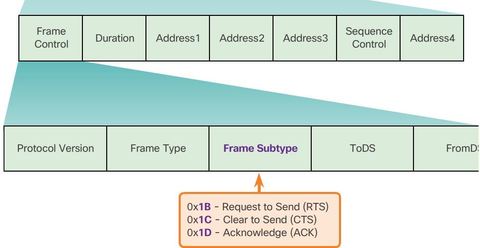
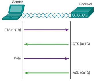
| Control Frames 1. Request to Send (RTS) frame - The RTS and CTS frames provide an optional collision reduction scheme for APs with hidden wireless clients. A wireless client sends an RTS frame as the first step in the two-way handshake, which is required before sending data frames. ** Control frames are integral to wireless transmission and play a significant role in the media contention method used by wireless, known as: Carrier Sense Multiple Access with Collision Avoidance (CSMA/CA). - “acceso múltiple por detección de portadora y prevención de colisiones” | |
| Control Frames 2. Clear to Send (CTS) frame - A wireless AP responds to an RTS frame with a CTS frame. It provides clearance for the requesting wireless client to send a data frame. The CTS contributes to collision control management by including a time value. This time delay minimizes the chance that other wireless clients will transmit while the requesting client transmits. 3. Acknowledgment (ACK) frame - After receiving a data frame, the receiving wireless client sends an ACK frame to the sending client if no errors are found. If the sending client does not receive an ACK frame within a predetermined period of time, the sending client resends the frame. | |
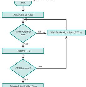
| Carrier Sense Multiple Access with Collision Avoidance * Wi-Fi systems are half-duplex, shared media configurations; therefore, wireless clients can transmit and receive on the same radio channel. This creates a problem because a wireless client cannot hear while it is sending; thus, making it impossible to detect a collision. To address this problem, the IEEE developed an additional collision avoidance mechanism called the Distributed Coordination Function (DCF). Using DCF, a wireless client transmits only if the channel is clear. All transmissions are acknowledged; therefore, if a wireless client does not receive an acknowledgment, it assumes a collision occurred and retries after a random waiting interval. | |
| Carrier Sense Multiple Access with Collision Avoidance Ej: when a wireless client sends data, it first senses the media to determine if other devices are transmitting. If not, it then sends an RTS frame to the AP. This frame is used to request dedicated access to the RF medium for a specified duration. The AP receives the frame and, if available, grants the wireless client access to the RF medium by sending a CTS frame of the same time duration. All other wireless devices observing the CTS frame relinquish the media to the transmitting node for transmission. The CTS control frame includes the time duration that the transmitting node is allowed to transmit. Other wireless clients withhold transmissions for, at least, the specified duration. | |
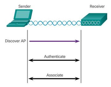
| Wireless Clients and Access Point Association Management frames are used by wireless devices to complete the following three-stage process: 1. Discover new wireless AP. 2. Authenticate with AP. 3. Associate with AP. Para asociarse, un cliente inalámbrico y un AP deben acordar parámetros específicos. Para permitir la negociación de estos procesos, se deben configurar los parámetros en el AP y posteriormente en el cliente. | |
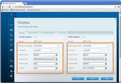
| Association Parameters * SSID: un SSID es un identificador único que usan los clientes inalámbricos para distinguir entre varias redes inalámbricas en la misma área. Según la configuración de la red, varios AP en una red pueden compartir un SSID. ** La configuración Mixed proporciona más flexibilidad, pero también puede lentificar la comunicación. Por ejemplo, si todos los clientes inalámbricos que se conectan al router usan 802.11n, todos disfrutan de las mejores velocidades de datos que se proporcionan. Si un cliente inalámbrico 802.11g se asocia al AP, todos los clientes inalámbricos más rápidos que compiten por el canal deben esperar a que los clientes 802.11g despejen el canal antes de transmitir Los Linksys EA6500 no admite 802.11ad. | |
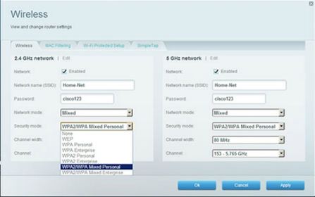
| Association Parameters Las opciones de Security que se indican en la figura 4 son opciones de protocolos de seguridad disponibles en el router inalámbrico Linksys EA6500. ** Los usuarios domésticos deben elegir WPA2/WPA Mixed Personal (WPA2/WPA personal combinado), mientras que los usuarios empresariales normalmente eligen WPA2/WPA Mixed Enterprise (WPA2/WPA empresarial combinado). | |
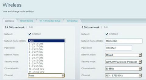
| Association Parameters Ej: se muestran las opciones de Channel settings para el alcance de 2,4 GHz. La opción preferida es Auto (Automático); sin embargo, si hubiera otros AP u otros dispositivos cercanos que interfirieran en el canal seleccionado por el router, se podría seleccionar un canal específico. Si bien el alcance de 5 GHz también tiene la opción Auto, en el ejemplo, se indica un canal (153) y un ancho de canal específicos. | |
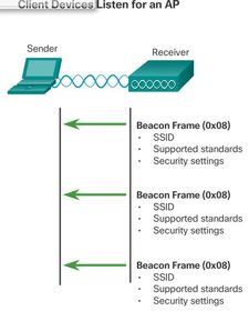
| Discovering Aps 1. Passive mode - The AP openly advertises its service by periodically sending broadcast beacon frames containing the SSID, supported standards, and security settings. The primary purpose of the beacon is to allow wireless clients to learn which networks and APs are available in a given area, thereby allowing them to choose which network and AP to use. | |
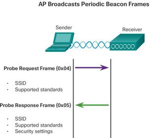
| Discovering Aps 2. Active mode - Wireless clients must know the name of the SSID. The wireless client initiates the process by broadcasting a probe request frame on multiple channels. The probe request includes the SSID name and standards supported. Active mode may be required if an AP or wireless router is configured to not broadcast beacon frames. ** A wireless client could also send a probe request without an SSID name to discover nearby WLAN networks. APs configured to broadcast beacon frames would respond to the wireless client with a probe response and provide the SSID name. APs with the broadcast SSID feature disabled do not respond. | |
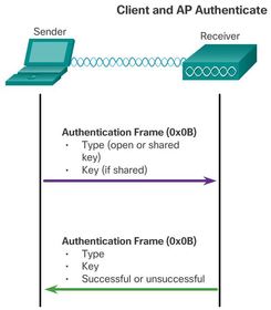
| Authentication 1. Open authentication - Fundamentally a NULL authentication where the wireless client says “authenticate me” and the AP responds with “yes”. Open authentication provides wireless connectivity to any wireless device 2. Shared key authentication - Technique is based on a key that is pre-shared between the client and the AP. * After a wireless client has associated with an AP, traffic is now able to flow between the client and the AP. | |
| Authentication ** In most shared key authentication installations, the exchange is as follows: 1. The wireless client sends an authentication frame to the AP. 2. The AP responds with a challenge text to the client. | 3. The client encrypts the message using its shared key and returns the encrypted text back to the AP. 4. The AP then decrypts the encrypted text using its shared key. 5. If the decrypted text matches the challenge text, the AP authenticates the client. If the messages do not match, the wireless client is not authenticated and wireless access is denied. |
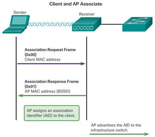
| Authentication After a wireless client has been authenticated, the AP proceeds to the association stage. 1. The wireless client forwards an Association Request frame that includes its MAC address. 2. The AP responds with an Associate Response that includes the AP BSSID, which is the AP MAC address. ** 3. The AP maps a logical port known as the association identifier (AID) to the wireless client. The AID is equivalent to a port on a switch and allows the infrastructure switch to keep track of frames destined for the wireless client to be forwarded. | |
| Frequency Channel Saturation As previously explained, wireless LAN devices have transmitters and receivers tuned to specific frequencies of radio waves to communicate. ** A common practice is for frequencies to be allocated as ranges. Such ranges are then split into smaller ranges called channels. | If the demand for a specific channel is too high, that channel is likely to become oversaturated. The saturation of the wireless medium degrades the quality of the communication. Over the years, a number of techniques have been created to improve wireless communication and alleviate saturation. |
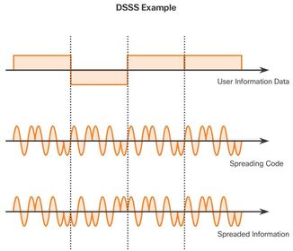
| Frequency Channel Saturation * Direct-sequence spread spectrum (DSSS) - DSSS is a spread-spectrum modulation technique. Spread-spectrum is designed to spread a signal over a larger frequency band making it more resistant to interference. With DSSS the signal is multiplied by a “crafted noise” known as a spreading code. Because the receiver knows about the spreading code and when it was added, it can mathematically remove it and re-construct the original signal. In effect, this creates redundancy in the transmitted signal in an effort to counter quality loss in the wireless medium. ** DSSS is used by 802.11b. Also used by cordless phones operating in the 900 MHz, 2.4 GHz, 5.8 GHz bands, CDMA cellular, and GPS networks. | |
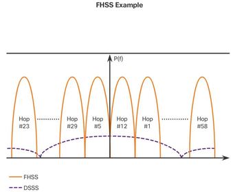
| Frequency Channel Saturation * Frequency-hopping spread spectrum (FHSS) - FHSS also relies on spread-spectrum methods to communicate. It is similar to DSSS but transmits radio signals by rapidly switching a carrier signal among many frequency channels. With the FHSS, sender and receiver must be synchronized to “know” which channel to jump. This channel hopping process allows for a more efficient usage of the channels, decreasing channel congestion. ** Walkie-talkies and 900 MHz cordless phones also use FHSS, and Bluetooth uses a variation of FHSS. FHSS is also used by the original 802.11 standard. | |
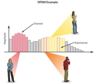
| Frequency Channel Saturation * Orthogonal frequency-division multiplexing (OFDM) - OFDM is a subset of frequency division multiplexing in which a single channel utilizes multiple sub-channels on adjacent frequencies. Sub-channels in an OFDM system are precisely orthogonal to one another which allow the sub-channels to overlap without interfering. As a result, OFDM systems are able to maximize spectral efficiency without causing adjacent channel interference. In effect, this makes it easier for a receiving station to “hear” the signal. Because OFDM uses sub-channels, channel usage is very efficient. ** OFDM is used by a number of communication systems including 802.11a/g/n/ac. | |
| Selecting Channels 802.11 standard operates in the 2.4 GHz, 5 GHz, and 60 GHz bands Each spectrum is subdivided into channels with a center frequency and bandwidth, analogous to the way radio bands are subdivided. | |
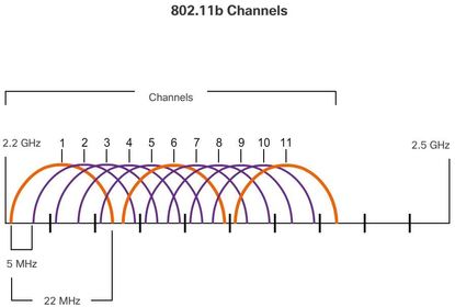
| Selecting Channels * The 2.4 GHz band is subdivided into multiple channels. The overall, combined channel bandwidth is 22 MHz with each channel separated by 5 MHz. The 802.11b standard identifies 11 channels for North America. The 22 MHz bandwidth, combined with the 5 MHz separation between frequencies, results in an overlap between successive channels Note: In Europe, there are 13 802.11b channels. | |
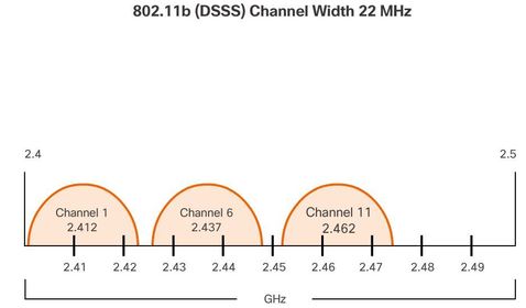
| Selecting Channels Interference occurs when an undesired signal overlaps a channel reserved for a desired signal, causing possible distortion. ** The solution to interference is to use non-overlapping channels. Specifically, channels 1, 6, and 11 are non-overlapping 802.11b channels, A best practice for WLANs requiring multiple APs is to use non-overlapping channels. If there are three adjacent APs, use channels 1, 6, and 11. If there are just two, select any two that are five channels apart, such as channels 5 and 10. Most APs can automatically select a channel based on adjacent channels used. Some products continuously monitor the radio space to adjust the channel settings dynamically in response to environmental changes. | |
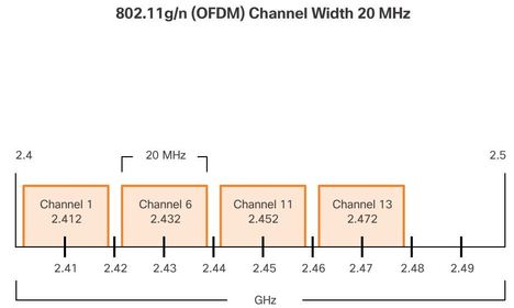
| Selecting Channels * As enterprise WLANs migrate to 802.11n, they can use channels in the larger, less-crowded 5 GHz band, reducing “accidental denial of service (DoS)”. Ej: For instance, the 802.11n standard uses OFDM and can support three non-overlapping channels, | |
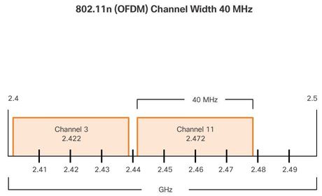
| Selecting Channels ** 802.11n can also use channel bonding, which combines two 20 MHz channel into one 40 MHz channel, Channel bonding increase throughput by using two channels at one time to deliver data. Most modern APs can auto-adjust channels to circumvent interference. * Note: IEEE 802.11ac uses OFDM with channels widths of 80, 160, and 80+80. | |
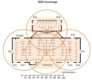
| Planning a WLAN Deployment ** The number or users depends on the geographical layout of the facility, including the number of bodies and devices that can fit in a space, the data rates users expect, the use of non-overlapping channels by multiple APs in an ESS, and transmit power settings. The approximate circular coverage area is important, but there are some additional recommendations: * Position APs above obstructions. | * If APs are to use existing wiring or if there are locations where APs cannot be placed, note these locations on the map. * Position APs vertically near the ceiling in the center of each coverage area, if possible. * Position APs in locations where users are expected to be. For example, conference rooms are typically a better location for APs than a hallway. |
| Planning a WLAN Deployment When these points have been addressed, estimate the expected coverage area of an AP. This value varies depending on the WLAN standard or mix of standards that are deployed, the nature of the facility, the transmit power that the AP is configured for, and so on. Always consult the specifications for the AP when planning for coverage areas. ** BSAs represent the coverage area provided by a single channel. An ESS should have 10 to 15 percent overlap between BSAs in an ESS. With a 15 percent overlap between BSAs, an SSID, and non-overlapping channels (i.e., one cell on channel 1 and the other on channel 6), roaming capability can be created. | |
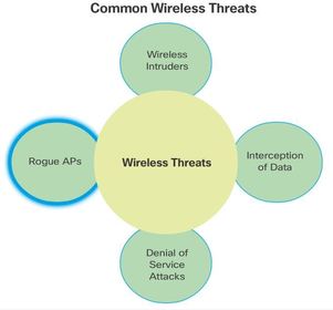
| Securing Wireless * Rouge Aps - Unauthorized APs installed by a well-intentioned user or willingly for malicious. Note: Other threats, such as AP/wireless client MAC spoofing, cracking, and infrastructure attacks are outside the scope of this chapter. | |
| DoS Attack 1. Improperly configured devices - For instance, an administrator could accidently alter a configuration and disable the network, or an intruder with administrator privileges could intentionally disable a WLAN. 2. A malicious user intentionally interfering with the wireless communication - Their goal is to disable the wireless network completely or to the point where no legitimate device can access the medium. | 3. Accidental interference - may occur from such devices as microwave ovens, cordless phones, baby monitors, and more. The 2.4 GHz band is more prone to interference than the 5 GHz band. ** The Cisco CleanAir technology - enables devices to identify and locate non-802.11 interference sources. It creates a network that has the ability to adjust automatically to changes in its environment. |
| Management Frame DoS Attacks Although unlikely, a malicious user could intentionally initiate a DoS attack using RF jamming devices that produce accidental interference. It is likelier that they will attempt to manipulate management frames to consume the AP resources and keep channels too busy to service legitimate user traffic. ** To mitigate many of these attacks, Cisco has developed a variety of solutions, including the Cisco Management Frame Protection (MFP) feature, which also provides complete proactive protection against frame and device spoofing. | The Cisco Adaptive Wireless IPS contributes to this solution by an early detection system where the attack signatures are matched. ** The IEEE 802.11 committee has also released two standards in regards to wireless security. The "802.11i" standard, which is based on Cisco MFP, specifies security mechanisms for wireless networks while the "802.11w" management frame protection standard addresses the problem of manipulating management frames. |
| Management Frame DoS Attacks Management frames can be manipulated to create various types of DoS attacks. Two common management frame attacks include: ** A spoofed disconnect attack - This occurs when an attacker sends a series of “disassociate” commands to all wireless clients within a BSS. These commands cause all clients to disconnect. When disconnected, the wireless clients immediately try to re-associate, which creates a burst of traffic. The attacker continues sending disassociate frames and the cycle repeats itself | ** A CTS flood - This occurs when an attacker takes advantage of the CSMA/CA contention method to monopolize the bandwidth and deny all other wireless clients access to the AP. To accomplish this, the attacker repeatedly floods the BSS with Clear to Send (CTS) frames to a bogus STA. All other wireless clients sharing the RF medium receive the CTS and withhold their transmissions until the attacker stops transmitting the CTS frames. ** Note: This is only one example of a management frame attack. There are many others that exist. |
| Rogue Access Points A rogue AP is an AP or wireless router that has either been: * Connected or enabled by an attacker to capture client data such as the MAC addresses of clients (both wireless and wired), or to capture and disguise data packets, to gain access to network resources, or to launch man-in-the-middle attack. | * Connected to a corporate network without explicit authorization and against corporate policy. Anyone with access to the premises can install (maliciously or non-maliciously) an inexpensive wireless router that can potentially allow access to a secure network resources. |
| Rogue Access Points Another consideration is how easy it is to create a personal network hotspot. For example, a user with secure network access enables their authorized Windows host to become a Wi-Fi AP. Doing so circumvents the security measures and other unauthorized devices can now access network resources as a shared device. | ** To prevent the installation of rogue APs, organizations must use monitoring software to actively monitor the radio spectrum for unauthorized APs. For example, the sample Cisco Prime Infrastructure network management software displays an RF map identifying the location of an intruder with a spoofed MAC address detected. |
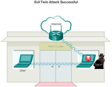
| Man-in-the-Middle Attack A popular wireless MITM attack is called the “evil twin AP” attack, where an attacker introduces a rogue AP and configures it with the same SSID as a legitimate AP. Connecting wireless clients would see two APs offering wireless access. Those near the rogue AP find the stronger signal and most likely associate with the evil twin AP. User traffic is now sent to the rogue AP, which in turn captures the data and forwards it to the legitimate AP. Return traffic from the legitimate AP is sent to the rogue AP, captured, and then forwarded to the unsuspecting STA. | |
| Man-in-the-Middle Attack Defeating an attack like an MITM attack depends on the sophistication of the WLAN infrastructure and the vigilance in monitoring activity on the network. ** The process begins with identifying legitimate devices on the WLAN. To do this, users must be authenticated. After all of the legitimate devices are known, the network can be monitored for abnormal devices or traffic. | Enterprise WLANs that use state-of-the-art WLAN devices provide administrators with tools that work together as a wireless intrusion prevention system (IPS). ** These tools include scanners that identify rogue APs and ad hoc networks, and radio resource management (RRM), which monitors the RF band for activity and AP load. An AP that is busier than normal alerts the administrator of possible unauthorized traffic. |
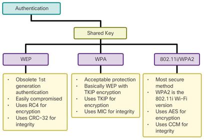
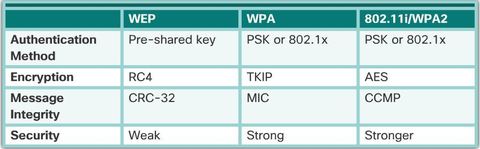
| Shared Key Authentication Methods * Wired Equivalent Privacy (WEP) - Original 802.11 specification designed to provide privacy similar to connecting to a network using a wired connection. The data is secured using the RC4 encryption method with a static key. However, the key never changes when exchanging packets making it easy to hack. * Wi-Fi Protected Access (WPA) - A Wi-Fi Alliance standard that uses WEP, but secures the data with the much stronger Temporal Key Integrity Protocol (TKIP) encryption algorithm. TKIP changes the key for each packet making it much more difficult to hack. | |
| Shared Key Authentication Methods * IEEE 802.11i/WPA2 - IEEE 802.11i is the industry standard for securing wireless networks. The Wi-Fi alliance version is called WPA2. 802.11i and WPA2; both use the Advanced Encryption Standard (AES) for encryption. AES is currently considered the strongest encryption protocol ** . Note: Wireless-N networks should use the WPA2-Personal security mode for best performance. | |
| Encryption Methods ** Temporal Key Integrity Protocol (TKIP) - TKIP is the encryption method used by WPA. It provides support for legacy WLAN equipment by addressing the original flaws associated with the 802.11 WEP encryption method. It makes use of WEP, but encrypts the Layer 2 payload using TKIP, and carries out a Message Integrity Check (MIC) in the encrypted packet to ensure the message has not been tampered with. | * Advanced Encryption Standard (AES) - AES is the encryption method used by WPA2. It is the preferred method because it aligns with the industry standard IEEE 802.11i. AES performs the same functions as TKIP, but it is a far stronger method of encryption. It uses the: -- Counter Cipher Mode with Block Chaining Message Authentication Code Protocol (CCMP) that allows destination hosts to recognize if the encrypted and non-encrypted bits have been tampered with. ** Note: Always choose WPA2 with AES when possible. |
| WPA and WPA2 support two types of authentication: 1. Personal - Intended for home or small office networks, users authenticate using a pre-shared key (PSK). Wireless clients authenticate with the AP using a pre-shared password. No special authentication server is required. 2. Enterprise - Intended for enterprise networks but requires a Remote Authentication Dial-In User Service (RADIUS) authentication server. Although more complicated to set up, it provides additional security. | The device must be authenticated by the RADIUS server and then users must authenticate using 802.1X standard, which uses the Extensible Authentication Protocol (EAP) for authentication. The 802.1X login process uses EAP to communicate with the AP and RADIUS server. EAP is a framework for authenticating network access. It can provide a secure authentication mechanism and negotiate a secure private key that can then be used for a wireless encryption session utilizing TKIP or AES encryption. |
| Authentication in the Enterprise The Enterprise security mode choices require an Authentication, Authorization, and Accounting (AAA) RADIUS server. These fields are necessary to supply the AP with the required information to contact the AAA server: 1. RADIUS Server IP address - This is the reachable address of the RADIUS server. | 2. RADIUS port numbers - Officially assigned UDP ports 1812 for RADIUS Authentication and 1813 for RADIUS Accounting, but could also operate using UDP ports 1645 and 1646, as shown in the figure 3. Shared key - Used to authenticate the AP with the RADIUS server. ** Note: There is no Password field listed, because the actual user authentication and authorization is handled by the 802.1X standard, which provides a centralized, server-based authentication of end users. |
| Troubleshooting Approaches When troubleshooting, these layered models can be applied to the physical network to isolate network problems. For example, if the symptoms suggest a physical connection problem, the network technician can focus on troubleshooting the circuit that operates at the physical layer. If that circuit functions properly, the technician looks at areas in another layer that could be causing the problem. | There are three main troubleshooting approaches used to resolve network problems: * Bottom-up - Start at Layer 1 and work up. * Top-down - Start at the top layer and work down. * Divide-and-conquer - Ping the destination. If the pings fail, verify the lower layers. If the pings are successful, verify the upper layers. |
| Troubleshooting When the Network Is Slow * Upgrade your wireless clients - Older 802.11b and even 802.11g devices can slow the entire WLAN. For the best performance, all wireless devices should support the same highest acceptable standard. * Split the traffic - The easiest way to improve wireless performance is to split the wireless traffic between the 802.11n 2.4 GHz band and the 5 GHz band. Therefore, 802.11n (or better) can use the two bands as two separate wireless networks to help manage the traffic. | There are several reasons for using a split-the-traffic approach: * The 2.4 GHz band may be suitable for basic Internet traffic that is not time-sensitive. * The bandwidth may still be shared with other nearby WLANs. * The 5 GHz band is much less crowded than the 2.4 GHz band; ideal for streaming multimedia. * The 5 GHz band has more channels; therefore, the channel chosen is likely interference-free. |
Want to create your own Flashcards for free with GoConqr? Learn more.