6162227
Description
Flashcards by John Dedios, updated more than 1 year ago
|
|
Created by John Dedios
over 7 years ago
|
|
| Question | Answer |
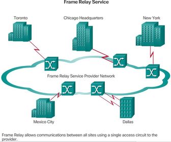
| Frame Relay An alternative to dedicated, expensive, leased WAN lines is Frame Relay. Frame Relay is a high-performance WAN protocol that operates at the physical and data link layers of the OSI reference model | Although newer services such as broadband and metro Ethernet have reduced the need for Frame Relay in many locations, Frame Relay is still a viable option in many locales around the world. Frame Relay provides a cost-efficient solution for communications between multiple remote sites by using a single access circuit from each site to the provider. |
| Frame Relay Unlike leased lines, Frame Relay requires only a single access circuit to the Frame Relay provider to communicate with other sites connected to the same provider. The capacity between any two sites can vary. The Frame Relay network handles the transmission over a frequently changing path transparent to all end users. | |
| Frame Relay Eric Scace, an engineer at Sprint International, invented Frame Relay as a simpler version of the X.25 protocol to use across Integrated Services Digital Network (ISDN) interfaces. Today, it is also used over a variety of other network interfaces. When Sprint first implemented Frame Relay in its public network, they used StrataCom switches. Cisco’s acquisition of StrataCom in 1996 marked their entry into the carrier market. | Historically, Frame Relay was used extensively as a WAN protocol because it was inexpensive compared to dedicated leased lines. In addition, configuring user equipment in a Frame Relay network is very simple. Frame Relay connections are created by configuring customer premise equipment (CPE) routers or other devices to communicate with a service provider Frame Relay switch. The service provider configures the Frame Relay switch, which helps keep end-user configuration tasks to a minimum. |
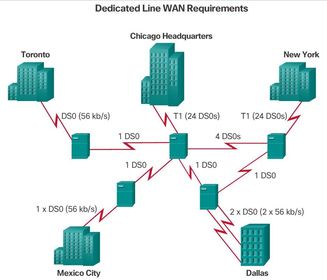
| Dedicated Line Requirements A dedicated line provides little practical opportunity for a one-to-many connection without getting more lines from the network provider. Ej: almost all communication must flow through the corporate headquarters, simply to reduce the cost of additional lines. The leased-line design also limits flexibility. Unless circuits are already installed, connecting new sites typically requires new circuit installations and takes considerable time to implement. | |
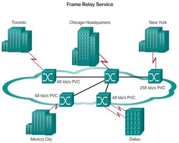
| Cost Effectiveness and Flexibility of Frame Relay SPAN’s Frame Relay network uses Permanent Virtual Circuits (PVCs), A PVC is the logical path along an originating Frame Relay link, through the network, and along a terminating Frame Relay link to its ultimate destination. In a network with Frame Relay access, a PVC uniquely defines the path between two endpoints. | |
| Cost Effectiveness of Frame Relay Frame Relay is a more cost-effective option for two reasons. First, with dedicated lines, customers pay for an end-to-end connection, which includes the local loop and the network link. With Frame Relay, customers only pay for the local loop, and for the bandwidth they purchase from the network provider. Distance between nodes is not important. While in a dedicated-line model, customers use dedicated lines provided in increments of 64 kb/s, and Frame Relay customers can define their virtual circuit needs in far greater granularity, often in increments as small as 4 kb/s. | * The second reason for Frame Relay’s cost effectiveness is that it shares bandwidth across a larger base of customers. Typically, a network provider can service 40 or more 56 kb/s customers over one T1 circuit. Using dedicated lines would require more CSU/DSUs (one for each line) and more complicated routing and switching. Network providers save because there is less equipment to purchase and maintain |
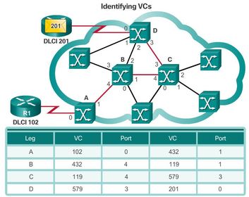
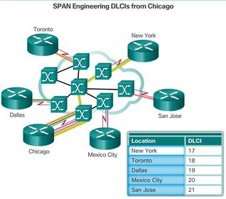
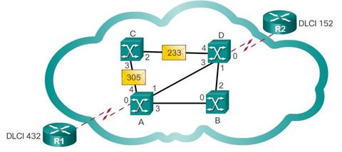
| The Flexibility of Frame Relay A virtual circuit provides considerable flexibility in network design. Examining the figure, you can see that SPAN’s offices all connect to the Frame Relay cloud over their respective local loops. What happens in the cloud is really of no concern at this time. ** All that matters is that when any SPAN office wants to communicate with any other SPAN office, all it needs to do is connect to a virtual circuit leading to the other office. | In Frame Relay, the end of each connection has a number to identify it called a data link connection identifier (DLCI). Any station can connect with any other simply by stating the address of that station and DLCI number of the line it must use. |
| Virtual Circuits The connection through a Frame Relay network between two DTEs is a VC. The circuits are virtual because there is no direct electrical connection from end to end. The connection is logical, and data moves from end to end, without a direct electrical circuit. With VCs, Frame Relay shares the bandwidth among multiple users and any single site can communicate with any other single site without using multiple dedicated physical lines. | There are two ways to establish VCs: a. Switched Virtual Circuits (SVC) - Established dynamically by sending signaling messages to the network (CALL SETUP, DATA TRANSFER, IDLE, CALL TERMINATION). b. Permanent Virtual Circuits (PVCs) - preconfigured by the carrier, and after they are set up, only operate in DATA TRANSFER and IDLE modes. Note that some publications refer to PVCs as private VCs. Note: PVCs are more commonly implemented than SVCs. |
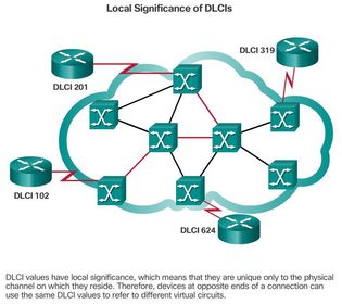
| Virtual Circuits Locally significant DLCIs have become the primary method of addressing, because the same address can be used in several different locations while still referring to different connections. Local addressing prevents a customer from running out of DLCIs as the network grows. | |
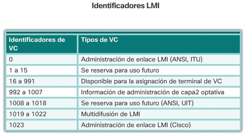
| Virtual Circuits Ej: Frame Relay labels each VC with a DLCI. The DLCI is stored in the address field of every frame transmitted to tell the network how the frame should be routed. The Frame Relay service provider assigns DLCI numbers. Usually, DLCIs 0 to 15 and 1,008 to 1,023 are reserved. Therefore, service providers typically assign DLCIs in the range of 16 to 1,007. | |
| Multiple Virtual Circuits Frame Relay is statistically multiplexed, meaning that it transmits only one frame at a time, but that many logical connections can co-exist on a single physical line. ** The Frame Relay Access Device (FRAD), or router connected to the Frame Relay network, may have multiple VCs connecting it to various endpoints. Multiple VCs on a single physical line are distinguished because each VC has its own DLCI | This capability often reduces the equipment and network complexity required to connect multiple devices, making it a very cost-effective replacement for a mesh of access lines. With this configuration, each endpoint needs only a single access line and interface. More savings arise as the capacity of the access line is based on the average bandwidth requirement of the VCs, rather than on the maximum bandwidth requirement. |
| Cost Benefits of Multiple VCs With Frame Relay, customers pay for the bandwidth they use. In effect, they pay for a Frame Relay port. When the customer increases the number of ports, as described above, they pay for more bandwidth, but they do not pay for more equipment because the ports are virtual. There is no change to the physical infrastructure. Compare this to purchasing more bandwidth using dedicated lines. | |
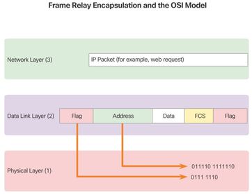
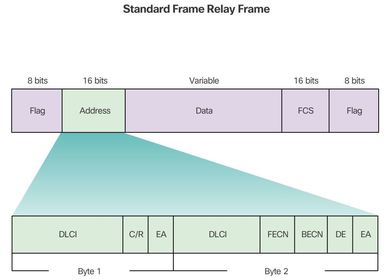
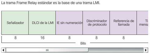
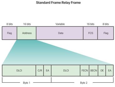
| Frame Relay Encapsulation First, Frame Relay accepts a packet from a network layer protocol, such as IPv4. It then wraps it with an address field that contains the DLCI and a checksum. Flag fields are added to indicate the beginning and end of the frame. The flag fields mark the start and end of the frame and are always the same. The flags are represented either as the hexadecimal number 7E or as the binary number 01111110. After the packet is encapsulated, Frame Relay passes the frame to the physical layer for transport. The header and trailer are defined by the Link Access Procedure for Frame Relay (LAPF) Bearer Services specification, ITU Q.922-A. | |
| Frame Relay Encapsulation * DLCI - The 10-bit DLCI is one of the most important fields in the Frame Relay header. This value represents the virtual connection between the DTE device and the switch. Each virtual connection that is multiplexed on to the physical channel is represented by a unique DLCI. * C/R - The C/R bit is not currently defined. | |
| Frame Relay Encapsulation * Extended Address (EA) - If the value of the EA field is 1, the current byte is determined to be the last DLCI octet. Although current Frame Relay implementations all use a two-octet DLCI, this capability does allow longer DLCIs in the future. The eighth bit of each byte of the Address field indicates the EA. * Congestion Control - Consists of three Frame Relay congestion-notification bits. These three bits are specifically referred to as the Forward Explicit Congestion Notification (FECN), Backward Explicit Congestion Notification (BECN), and Discard Eligible bits. | |
| Frame Relay Encapsulation ** The physical layer is typically EIA/TIA-232, 449 or 530, V.35, or X.21. The Frame Relay frame is a subset of the HDLC frame type; therefore, it is delimited with flag fields. The 1-byte flag uses the bit pattern 01111110. The FCS determines whether any errors in the Layer 2 address field occurred during transmission. The FCS is calculated prior to transmission by the sending node, and the result is inserted in the FCS field. | At the distant end, a second FCS value is calculated and compared to the FCS in the frame. If the results are the same, the frame is processed. ** If there is a difference, the frame is discarded. Frame Relay does not notify the source when a frame is discarded. Error control is left to the upper layers of the OSI model. |
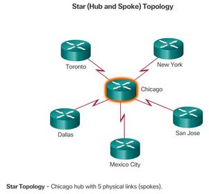
| Frame Relay Topologies - Star Topology (Hub and Spoke) Ej: Connections to each of the five remote sites act as spokes. In a star topology, the location of the hub is usually chosen by the lowest leased-line cost. When implementing a star topology with Frame Relay, each remote site has an access link to the Frame Relay cloud with a single VC. ** Complete topologies for design, implementation, operation, and maintenance include overview maps, logical connection maps, functional maps, and address maps showing the detailed equipment and channel links. | |
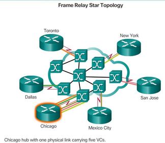
| Frame Relay Topologies - Star Topology (Hub and Spoke) Ej: shows the star topology in the context of a Frame Relay cloud. The hub at Chicago has an access link with multiple VCs, one for each remote site. The lines going out from the cloud represent the connections from the Frame Relay service provider and terminate at the customer premises. Because Frame Relay costs are not distance-related, the hub does not need to be in the geographical center of the network | |
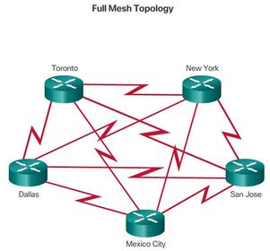
| Frame Relay Topologies - Full Mesh Topology ** A full mesh topology suits a situation in which the services to be accessed are geographically dispersed and highly reliable access to them is required. A full mesh topology connects every site to every other site. Using leased-line interconnections, additional serial interfaces and lines add costs. In this example, 10 dedicated lines are required to interconnect each site in a full mesh topology. | |
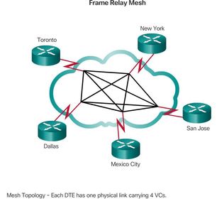
| Frame Relay Topologies - Full Mesh Topology Using Frame Relay Mesh, a network designer can build multiple connections simply by configuring additional VCs on each existing link Because VCs use statistical multiplexing, multiple VCs on an access link generally make better use of Frame Relay than single VCs. Service providers will charge for the additional bandwidth, but this solution is usually more cost effective than using dedicated lines | |
| Partial Mesh Topology For large networks, a full mesh topology is seldom affordable because the number of links required increases exponentially. ** The issue is not with the cost of the hardware, but because there is a theoretical limit of less than 1,000 VCs per link. In practice, the limit is less than that. | For this reason, larger networks are generally configured in a partial mesh topology. With partial mesh, there are more interconnections than required for a star arrangement, but not as many as for a full mesh. The actual pattern is dependent on the data flow requirements. |
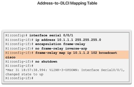
| Frame Relay Address Mapping Before a Cisco router is able to transmit data over Frame Relay, it needs to know which local DLCI maps to the Layer 3 address of the remote destination. This address-to-DLCI mapping can be accomplished either by static or dynamic mapping. | |
| Frame Relay Address Mapping Inverse ARP A primary tool of Frame Relay is Inverse Address Resolution Protocol (ARP). ** Whereas ARP translates Layer 3 IPv4 addresses to Layer 2 MAC addresses, Inverse ARP does the opposite. The corresponding Layer 3 IPv4 addresses must be available before VCs can be used. | Note: Frame Relay for IPv6 uses Inverse Neighbor Discovery (IND) to obtain a Layer 3 IPv6 address from a Layer 2 DLCI. A Frame Relay router sends an IND Solicitation message to request a Layer 3 IPv6 address corresponding to a Layer 2 DLCI address of the remote Frame Relay router. At the same time the IND Solicitation message provides the sender’s Layer 2 DLCI address to the remote Frame Relay router. |
| Frame Relay Address Mapping Dynamic Mapping Dynamic address mapping relies on Inverse ARP to resolve a next-hop network layer IPv4 address to a local DLCI value. The Frame Relay router sends out Inverse ARP requests on its PVC to discover the protocol address of the remote device connected to the Frame Relay network. | The router uses the responses to populate an address-to-DLCI mapping table on the Frame Relay router or access server. The router builds and maintains this mapping table, which contains all resolved Inverse ARP requests, including both dynamic and static mapping entries. ** On Cisco routers, Inverse ARP is enabled, by default, for all protocols enabled on the physical interface. Inverse ARP packets are not sent out for protocols that are not enabled on the interface. |
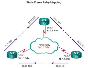
| Frame Relay Address Mapping Static Frame Relay Mapping The user can choose to override dynamic Inverse ARP mapping by supplying a manual static map for the next-hop protocol address to a local DLCI. ** A static map works similarly to dynamic Inverse ARP by associating a specified next-hop protocol address to a local Frame Relay DLCI. You cannot use Inverse ARP and a map statement for the same DLCI and protocol. | Another example is on a hub-and-spoke Frame Relay network. ** Use static address mapping on the spoke routers to provide spoke-to-spoke reachability. Because the spoke routers do not have direct connectivity with each other, dynamic Inverse ARP would not work between them. ** Dynamic Inverse ARP relies on the presence of a direct point-to-point connection between two ends. In this case, dynamic Inverse ARP only works between hub and spoke, and the spokes require static mapping to provide reachability to each other. |
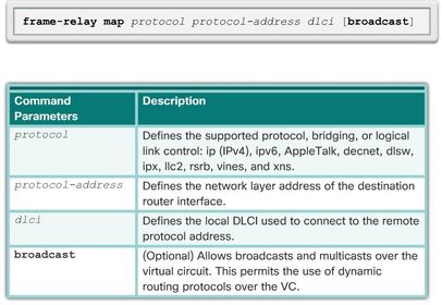
| Configuring Static Mapping To map between a next hop protocol address and DLCI destination address, use this command: frame-relay map (protocol) (protocol-address) (dlci) [broadcast] [ietf] [cisco]. Use the keyword ietf when connecting to a non-Cisco router. ** The configuration of Open Shortest Path First (OSPF) protocol can be greatly simplified by adding the optional "broadcast" keyword when doing this task. The broadcast keyword specifies that broadcast and multicast traffic is allowed over the VC. This configuration permits the use of dynamic routing protocols over the VC. | |
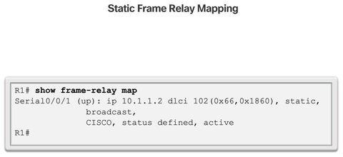
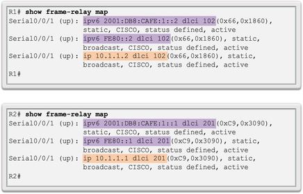
| Configuring Static Mapping Ej: shows the output of the show frame-relay map command. Notice that the interface is up and the destination IPv4 address is 10.1.1.2. The DLCI identifies the logical connection being used to reach this interface. This value is displayed in decimal value (102), in hexadecimal value (0x66), and as its value as it would appear on the wire (0x1860). This is a static entry, not a dynamic entry. The link is using Cisco encapsulation as opposed to IETF encapsulation. | |
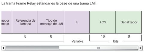
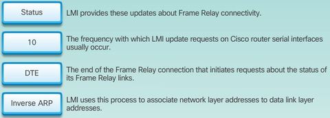
| Local Management Interface (LMI) Another important concept in Frame Relay is the Local Management Interface (LMI). The Frame Relay design provides packet-switched data transfer with minimum end-to-end delays. The original design omits anything that might contribute to delay. | A consortium of Cisco, Digital Equipment Corporation (DEC), Northern Telecom, and StrataCom extended the Frame Relay protocol to provide additional capabilities for complex internetworking environments. These extensions are referred to collectively as the LMI |
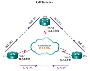
| Local Management Interface (LMI) Basically, the LMI is a keepalive mechanism that provides status information about Frame Relay connections between the router (DTE) and the Frame Relay switch (DCE). Every 10 seconds or so, the end device polls the network, either requesting a dumb sequenced response or channel status information. If the network does not respond with the requested information, the user device may consider the connection to be down. When the network responds with a FULL STATUS response, it includes status information about DLCIs that are allocated to that line. The end device can use this information to determine whether the logical connections are able to pass data. | |
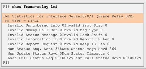
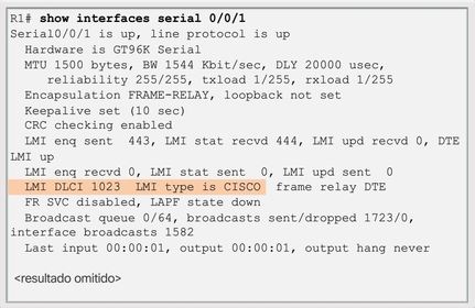
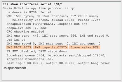
| Local Management Interface (LMI) Ej: ? The output shows the LMI type used by the Frame Relay interface and the counters for the LMI status exchange sequence, including errors such as LMI timeouts. ** It is easy to confuse the LMI and encapsulation. The LMI is a definition of the messages used between the DTE (R1) and the DCE (the Frame Relay switch owned by the service provider). Encapsulation defines the headers used by a DTE to communicate information to the DTE at the other end of a VC. The switch and its connected router care about using the same LMI. The switch does not care about the encapsulation. The endpoint routers (DTEs) do care about the encapsulation. | |
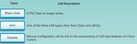
| Frame Relay specification includes optional LMI extensions. Some of the extensions include: * VC status messages - Provide information about PVC integrity by communicating and synchronizing between devices, periodically reporting the existence of new PVCs and the deletion of already existing PVCs. VC status messages prevent data from being sent into black holes (PVCs that no longer exist). | * Multicasting - Allows a sender to transmit a single frame that is delivered to multiple recipients. Multicasting supports the efficient delivery of routing protocol messages and address resolution procedures that are typically sent to many destinations simultaneously. |
| Frame Relay specification includes optional LMI extensions. Some of the extensions include: * Global addressing - Provides connection IDs with global rather than local significance, allowing them to be used to identify a specific interface to the Frame Relay network. Global addressing makes the Frame Relay network resemble a LAN in terms of addressing, and ARPs are used as on a LAN. | * Simple flow control - Provides for an XON/XOFF flow control mechanism that applies to the entire Frame Relay interface. It is intended for devices that cannot use the congestion notification bits (i.e., FECN and BECN) that would be leveraged by higher layers, but still require some level of flow control. |
| LMI Extensions LMI is used to manage Frame Relay links. Each LMI message is classified by a DLCI appearing in the LMI frame. The 10-bit DLCI field supports 1,024 VC IDs: 0 to 1,023, The LMI extensions reserve some of these VC IDs, thereby reducing the number of permitted VCs. LMI messages are exchanged between the DTE and DCE using these reserved DLCIs. | |
| LMI Extensions ** There are several LMI types, each of which is incompatible with the others. The LMI type configured on the router must match the type used by the service provider. Three types of LMIs are supported by Cisco routers: CISCO - Original LMI extension ANSI - Corresponding to the ANSI standard T1.617 Annex D Q933A - Corresponding to the ITU standard Q933 Annex A | |
| LMI Extensions Starting with the Cisco IOS software Release 11.2, the default LMI autosense feature detects the LMI type supported by the directly connected Frame Relay switch. ** Based on the LMI status messages it receives from the Frame Relay switch, the router automatically configures its interface with the supported LMI type acknowledged by the Frame Relay switch. ** If it is necessary to set the LMI type, use the "frame-relay lmi-type [cisco | ansi | q933a]" interface configuration command. Configuring the LMI type disables the autosense feature. | ** In cases where a Frame Relay switch uses non-default timeout settings, the keepalive interval must also be configured on the Frame Relay interface to prevent status exchange messages from timing out. ** The LMI status exchange messages determine the status of the PVC connection. A large mismatch in the keepalive interval on the router and the switch can cause the switch to declare the router dead. ** It is important to consult the Frame Relay service provider for information on how to modify the keepalive setting. By default, the keepalive time interval is 10 seconds on Cisco serial interfaces. You can change the keepalive interval with the keepalive interface configuration command |
| Using LMI and Inverse ARP to Map Addresses Ej: when R1 connects to the Frame Relay network, it sends an LMI status inquiry message to the network. The network replies with an LMI status message containing details of every VC configured on the access link. Periodically, the router repeats the status inquiry, but subsequent responses include only status changes. After a set number of these abbreviated responses, the network sends a full status message. | If the router needs to map VCs to network layer addresses, it sends an Inverse ARP message on each VC. Inverse ARP operates similarly to ARP on an Ethernet local network, with the exception that Inverse ARP does not broadcast requests. With ARP, the sending device knows the Layer 3 IP address and sends a broadcast to learn the destination Layer 2 MAC address. With Inverse ARP, the router knows the Layer 2 address, which is the local DLCI, and sends a request for the destination Layer 3 IP address. |
| Inverse ARP operation When an interface supporting Inverse ARP becomes active, it initiates the Inverse ARP protocol and formats an Inverse ARP request for the active VC. The Inverse ARP request includes the source hardware, source Layer 3 protocol address, and the known target hardware address. It then fills the target Layer 3 protocol address field with all zeroes. It encapsulates the packet for the specific network and sends it directly to the destination device using the VC. | Upon receiving an Inverse ARP request, the destination device will use the address of the source device to create its own DLCI-to-Layer 3 map. It will then send an Inverse ARP response that includes its Layer 3 address information. When the source device receives the Inverse ARP response, it completes the DLCI-to-Layer 3 map using the provided information. * LMI status messages combined with Inverse ARP messages allow a router to associate network layer and data link layer addresses. |
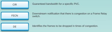
| Access Rate and Committed Information Rate Service providers build Frame Relay networks using very large and very powerful switches, but devices only see the switch interface of the service provider. Customers are usually not exposed to the inner workings of the network, which may be built on very high-speed technologies, such as SONET or SDH. | ** If the customer sends information faster than the CIR on a given DLCI, the network marks some frames with a Discard Eligibility (DE) bit. The network does its best to deliver all packets; however it discards DE packets first if there is congestion. Note: Many inexpensive Frame Relay services are based on a CIR of zero (0). A CIR of zero means that every frame is a DE frame and the network throws away any frame when it needs to. The DE bit is within the address field of the Frame Relay frame header. |
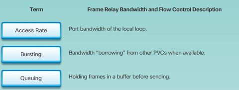
| Frame Relay services - a. Access rate refers to the port speed. From a customer’s point of view, the service provider provides a serial connection or access link to the Frame Relay network over a leased line. The access rate is the rate at which your access circuits join the Frame Relay network. These may be 56 kb/s, T1 (1.544 Mb/s), or Fractional T1 (a multiple of 56 kb/s or 64 kb/s). Access rates are clocked on the Frame Relay switch. It is not possible to send data at higher than the access rate. | b. Committed Information Rate (CIR) - Customers negotiate CIRs with service providers for each PVC. The CIR is the amount of data that the network receives from the access circuit. The service provider guarantees that the customer can send data at the CIR. All frames received at or below the CIR are accepted. The CIR specifies the maximum average data rate that the network undertakes to deliver under normal conditions. |
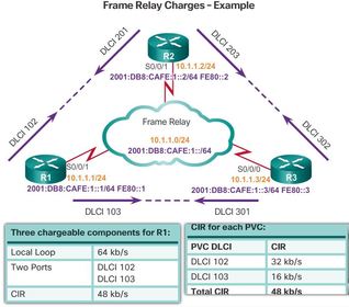
| Frame Relay Example 1. Access rate - The cost of the access line from the DTE to the DCE (customer to service provider). This line is charged based on the port speed that has been negotiated and installed. 2. PVC - This cost component is based on the PVCs. After a PVC is established, the additional cost to increase CIR is typically small and can be done in small (4 kb/s) increments. 3. CIR - Customers normally choose a CIR lower than the access rate. This allows them to take advantage of bursts | |
| Oversubscription Service providers sometimes sell more capacity than they have on the assumption that not everyone will demand their entitled capacity all of the time. This oversubscription is analogous to airlines selling more seats than they have in the expectation that some of the booked customers will not show up. | Because of oversubscription, there are instances when the sum of CIRs from multiple PVCs to a given location is higher than the port or access channel rate. This can cause congestion and dropped traffic. |
| Bursting A great advantage of Frame Relay is that any network capacity that is being unused is made available or shared with all customers, usually at no extra charge. This allows customers to burst over their CIR as a bonus. ** Ej: Bursting allows devices that temporarily need additional bandwidth to borrow it at no extra cost from other devices not using it. For example, if PVC 102 is transferring a large file, it could use any of the 16 kb/s not being used by PVC 103. A device can burst up to the access rate and still expect the data to get through. The duration of a burst transmission should be less than three or four seconds. | |
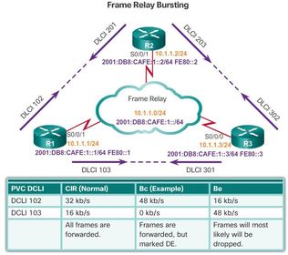
| Bursting Various terms are used to describe burst rates, including the Committed Burst Size (Bc) and Excess Burst Size (Be). 1. The Bc is a negotiated rate above the CIR that the customer can use to transmit for short burst, and represents the maximum allowed traffic under normal working conditions. It allows traffic to burst to higher speeds, as available network bandwidth permits | However, it cannot exceed the access rate of the link. A device can burst up to the Bc and still expect the data to get through. If long bursts persist, then a higher CIR should be purchased. 2. The Be describes the bandwidth available above the CIR up to the access rate of the link. Unlike the Bc, it is not negotiated. Frames may be transmitted at this level but are most likely dropped. |
| Bursting Ej: DLCI 102 has a CIR of 32 kb/s with an additional Bc of 16 kb/s for a total of up to 48 kb/s. DLCI 103 has a CIR of 16 kb/s. However, DLCI 103 does not have a Bc negotiated; therefore, the Bc is set to 0 kb/s. Frames within the negotiated CIR are not eligible for discard (DE = 0). Frames above the CIR have the DE bit set to 1, marking it as eligible to be discarded, should the network be congested. Frames submitted in the Bc level are marked as Discard Eligible (DE) in the frame header but will most likely be forwarded. | |
| Frame Relay Flow Control Frame Relay reduces network overhead by implementing simple congestion-notification mechanisms, rather than explicit, per-VC flow control. These congestion-notification mechanisms are the Forward Explicit Congestion Notification (FECN) and the Backward Explicit Congestion Notification (BECN). | Frames arriving at a switch are queued or buffered prior to forwarding. As in any queuing system, it is possible that there will be an excessive buildup of frames at a switch. This causes delays, which lead to unnecessary retransmissions that occur when higher level protocols receive no acknowledgment within a set time. In severe cases, this can cause a serious drop in network throughput. To avoid this problem, Frame Relay incorporates a flow control feature. |
| Frame Relay Flow Control FECN and BECN are each controlled by a single bit contained in the frame header. They let the router know that there is congestion and that the router should stop transmission until the condition is reversed. ** When the DCE sets the BECN bit to 1, it notifies devices in the direction of the source (upstream) that there is congestion on the network. When the DCE sets the FECN bit to 1, it notifies devices in the direction of the destination (downstream) that there is congestion on the network. | |
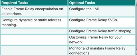
| Frame Relay Configuration TASKS | |
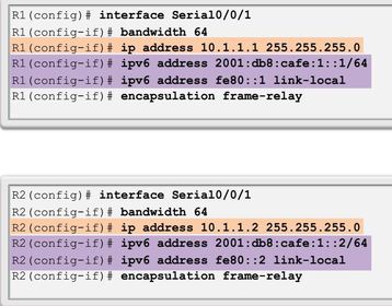
| Basic Frame Relay Configuration Commands * Step 1. Set the IP Address on the Interface * Step 2. Configure Encapsulation encapsulation frame-relay [cisco | ietf] ietf encapsulation type connecting to a non-Cisco router. * Step 3. Set the BandwidthStep * Step 4. Set the LMI Type (optional) | |
| Configuring a Static Frame Relay Map Ej: ? To map between a next hop protocol address and a DLCI destination address Static mapping is manually configured on a router. ** Dynamic mapping is performed by the Inverse ARP feature. Because Inverse ARP is enabled by default, no additional command is required to configure dynamic mapping on an interface. | |
| Configuring a Static Frame Relay Map ** Frame Relay, ATM, and X.25 are non-broadcast multiaccess (NBMA) networks. NBMA networks allow only data transfer from one computer to another, over a VC, or across a switching device. NBMA networks do not support multicast or broadcast traffic, so a single packet cannot reach all destinations. This requires you to replicate the packets manually to all destinations. | ** Using the "broadcast" keyword is a simplified way to forward routing updates. The broadcast keyword allows IPv4 broadcasts and multicasts to be propagated to all nodes. It also allows IPv6 multicasts over the PVC. When the keyword is enabled, the router converts the broadcast or multicast traffic into unicast traffic so that other nodes receive the routing updates. |
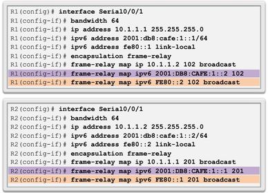
| Configuring a Static Frame Relay Map Ej: shows how to use the keywords when configuring static address maps. Notice that the first IPv6 Frame Relay map to a global unicast address does not include the broadcast keyword. ** However, the broadcast keyword is used in the mapping to the link-local address. IPv6 routing protocols use link-local addresses for multicast routing updates; therefore, only the link-local address map requires the broadcast keyword to forward multicast packets. | |
| Verify a Static Frame Relay Map Ej: ? To verify the Frame Relay mapping Notice that there are three Frame Relay maps. There is one map for IPv4 and two for IPv6, one for each of the IPv6 addresses. | |
| Reachability Issues By default, most Frame Relay networks provide NBMA connectivity, using a hub-and-spoke topology, between remote sites. ** In an NBMA Frame Relay topology, when a single multipoint interface must be used to interconnect multiple sites, routing update reachability issues may result. | ** With distance vector routing protocols, reachability issues may result from split horizon and multicast or broadcast replication. ** With link state routing protocols, issues with the DR/BDR election may result in reachability issues. |
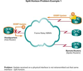
| Reachability Issues - Split Horizon The split horizon rule is a loop prevention mechanism for distance vector routing protocols such as EIGRP and RIP. It is not applicable to link-state routing protocols. Split horizon rule reduces routing loops by preventing a routing update that is received on an interface from being forwarded out the same interface. Ej: which is a hub-and-spoke Frame Relay topology, a remote router R2 (a spoke router) sends an update to the headquarters router R1 (the hub router). R1 is connecting multiple PVCs over a single physical interface. R1 receives the multicast on its physical interface; however, split horizon cannot forward that routing update through the same interface to other remote (spoke) routers. | |
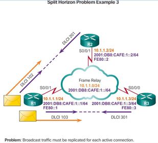
| Reachability Issues - Split Horizon Ej: displays a similar example using the reference topology used throughout this chapter. R2, a spoke router, sends a routing update to R1, a hub router. R1 has multiple PVCs on a single physical interface. The split horizon rule prevents R1 from forwarding that routing update through the same physical interface to the other remote spoke router (R3). Note: Split horizon is not an issue if only one PVC (a single remote connection) is configured on a physical interface. This type of connection is point-to-point. | |
| Reachability Issues - Multicast and Broadcast Replication Ej: due to split horizon, when a router supports multipoint connections over a single interface, the router must replicate broadcast or multicast packets. In the case of routing updates, the updates must be replicated and sent on each PVC to the remote routers. These replicated packets consume bandwidth and cause significant latency variations in user traffic. The amount of broadcast traffic and the number of VCs terminating at each router should be evaluated during the design phase of a Frame Relay network. Overhead traffic, such as routing updates, can affect the delivery of critical user data, especially when the delivery path contains low-bandwidth (56 kb/s) links. | |
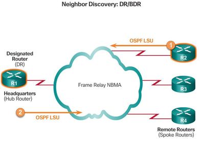
| Reachability Issues - Neighbor Discovery: DR and BDR Link-state routing protocols, such as OSPF, does not use the split horizon rule for loop prevention. However, reachability issues can arise with the DR/BDR. OSPF over NBMA networks works in non-broadcast network mode, by default, and neighbors are not automatically discovered. Neighbors can be statically configured. ** However, ensure that the hub router becomes a DR, Recall that a NBMA network behaves like Ethernet, and on Ethernet, a DR is needed to exchange routing information between all routers on a segment. Therefore, only the hub router can act as a DR, because it is the only router that has PVCs with all other routers. | |
| Solving Reachability Issues There are several ways to solve the routing reachability issue: 1. Disable split horizon - One method for solving the reachability issues that are produced by split horizon may be to turn off split horizon. ** However, disabling split horizon increases the chances of routing loops in your network. Additionally, only IP allows the ability to disable split horizon; IPX and AppleTalk do not. | 2. Full meshed topology - Another method is to use a fully meshed topology; however, this topology increases costs. 3. Subinterfaces - In a hub-and-spoke Frame Relay topology, the hub router can be configured with logically assigned interfaces called subinterfaces |
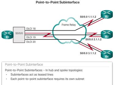
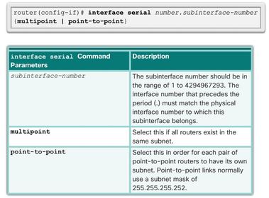
| Solving Reachability Issues Frame Relay subinterfaces can be configured in either point-to-point or multipoint mode: a. Point-to-point - A single point-to-point subinterface establishes one PVC connection to another physical interface or subinterface on a remote router. In this case, each pair of the point-to-point routers is on its own subnet, and each point-to-point subinterface has a single DLCI. In a point-to-point environment, each subinterface is acting like a point-to-point interface. For each point-to-point VC, there is a separate subnet. Therefore, routing update traffic is not subject to the split horizon rule. | |
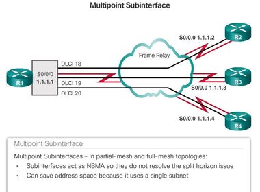
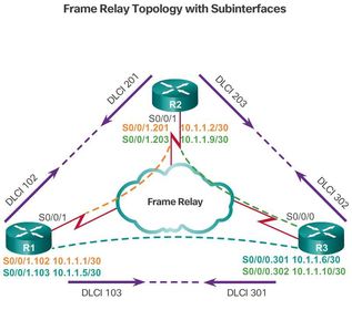
| Solving Reachability Issues Frame Relay subinterfaces can be configured in either point-to-point or multipoint mode: b. Multipoint (Figure 3) - A single multipoint subinterface establishes multiple PVC connections to multiple physical interfaces or subinterfaces on remote routers. All the participating interfaces are in the same subnet. ** The subinterface acts like an NBMA Frame Relay interface, so routing update traffic is subject to the split horizon rule. All multipoint VCs belong to the same subnet. | |
| Solving Reachability Issues Using a subinterface configuration, each VC can be configured as a point-to-point connection. A partially meshed network can be divided into a number of smaller, fully meshed, point-to-point networks. Each point-to-point subnetwork can be assigned a unique network address. This allows each subinterface to act similarly to a leased line. Using a Frame Relay point-to-point subinterface, each pair of the point-to-point routers is on its own subnet. | ** When configuring subinterfaces, the encapsulation frame-relay command is assigned to the physical interface. All other configuration items, such as the network layer address and DLCIs, are assigned to the subinterface. The multipoint subinterface configurations can be used to conserve addresses. This can be especially helpful if Variable Length Subnet Masking (VLSM) is not being used. However, multipoint configurations may not work properly given the broadcast traffic and split horizon considerations. The point-to-point subinterface option was created to avoid these issues. |
| Configuring Point-to-Point Subinterfaces Use the DLCI as the subinterface number. ** Note: Unfortunately, altering an existing Frame Relay subinterface configuration may fail to provide the expected result. In these situations, shut down the physical interface, make the appropriate changes to the subinterfaces and then re-enable the physical interface. If the corrected configuration produces unexpected results, then it may be necessary to save the configuration and reload the router. | |
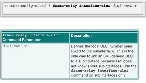
| Configuring Point-to-Point Subinterfaces ** If the subinterface is configured as point-to-point, the local DLCI for the subinterface must also be configured to distinguish it from the physical interface. The DLCI is also required for multipoint subinterfaces for which Inverse ARP is enabled for IPv4. It is not required for multipoint subinterfaces configured with static route maps. The Frame Relay service provider assigns the DLCI numbers. These numbers range from 16 to 992, and usually have only local significance. The range varies depending on the LMI used. | |
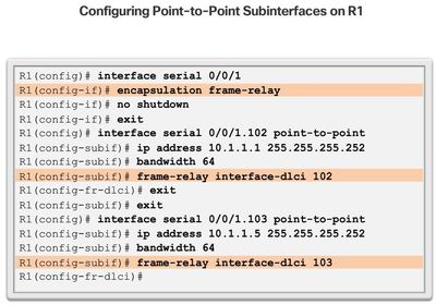
| Configuring Point-to-Point Subinterfaces Step 1. Remove any network layer address assigned to the physical interface. If the physical interface has an address, frames are not received by the local subinterfaces. Step 2. Configure Frame Relay encapsulation on the physical interface using the encapsulation frame-relay command. | Step 3. For each of the defined PVCs, create a logical subinterface. Specify the port number, followed by a period (.) and the subinterface number. Step 4. Configure an IP address for the interface and set the bandwidth. Step 5. Configure the local DLCI on the subinterface using the frame-relay interface-dlci command. Recall that the Frame Relay service provider assigns the DLCI numbers. |
| Verifying Frame Relay Operation: Frame Relay Interface 1. Verify Frame Relay Interfaces Ej: ? verify that Frame Relay is operating correctly on that interface A recommended best practice is to verify the configuration before problems appear. A verification procedure to ensure everything is working correctly before a configuration is launched on a live network. | |
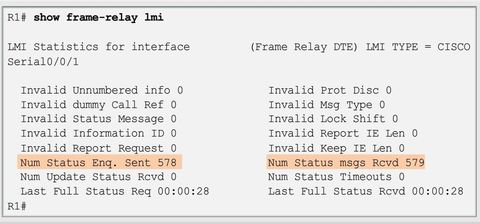
| Verifying Frame Relay Operation: LMI Operations Ej: ? to look at some LMI statistics Toutput that shows the number of status messages exchanged between the local router and the local Frame Relay switch. Ensure that the counters between status messages being sent and received are incrementing. This validates that there is active communication between the DTE and the DCE. Also look for any non-zero Invalid items. This helps isolate the problem of Frame Relay communications between the carrier’s switch and the client router. | |
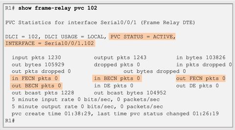
| Verifying Frame Relay Operation: PVC Status Ej: ? to view PVC and traffic statistics, and displays the status of all the PVCs configured on the router This command is also useful for viewing the number of BECN and FECN packets received by the router. The PVC status can be active, inactive, or deleted. After the statistics are gathered, use the clear counters command to reset the statistics counters. Wait 5 or 10 minutes after clearing the counters before issuing the show commands again. Note any additional errors. If you need to contact the carrier, these statistics help in resolving the issues. | |
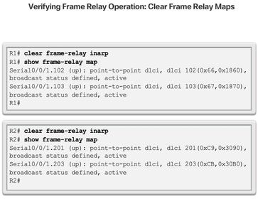
| Verifying Frame Relay Operation: Inverse ARP Ej: ? To clear dynamically created Frame Relay maps that are created using Inverse ARP Inverse ARP is enabled by default for IPv4. Frame Relay for IPv6 uses Inverse Neighbor Discovery (IND) to obtain a Layer 3 IPv6 address from a Layer 2 DLCI. | |
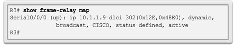
| Verifying Frame Relay Operation: Inverse ARP Ej: ? to display the current map entries and information about the connections. - 10.1.1.9 is the IPv4 address of the remote router, dynamically learned via the Inverse ARP process. - 302 is the decimal value of the local DLCI number. - 0x12E is the hex conversion of the DLCI number, 0x12E = 302 decimal. | |
| Verifying Frame Relay Operation: Inverse ARP Ej: ? to display the current map entries and information about the connections. - 0x48E0 is the value as it would appear on the wire because of the way the DLCI bits are spread out in the address field of the Frame Relay frame. - Broadcast/multicast is enabled on the PVC. - LMI type is cisco. - PVC status is active. | |
| Verifying Frame Relay Operation: Inverse ARP When an Inverse ARP request is made, the router updates its map table with three possible PVC connection states. These states are: - ACTIVE - Indicates a successful end-to-end (DTE to DTE) circuit. | - INACTIVE - Indicates a successful connection to the switch (DTE to DCE) without a DTE detected on the other end of the PVC. This can occur due to incorrect configuration on the switch. - DELETED - Indicates that the DTE is configured for a DLCI that the switch does not recognize as valid for that interface. |
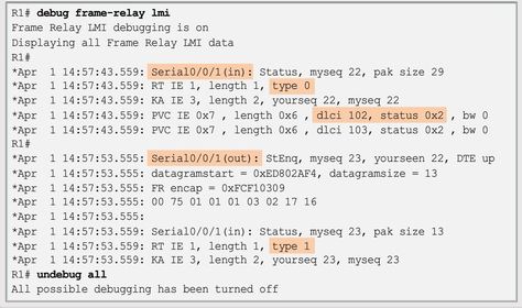
| Troubleshooting Frame Relay Operation Ej: ? to determine whether the router and the Frame Relay switch are sending and receiving LMI packets properly. - out is an LMI status message sent by the router. - in is a message received from the Frame Relay switch. - A full LMI status message is a type 0. - An LMI exchange is a type 1. - dlci 102, status 0x2 means that the status of DLCI 102 is active. | |
| Troubleshooting Frame Relay Operation The possible values of the status field are as follows: - 0x0 - The switch has this DLCI programmed, but for some reason it is not usable. The reason could possibly be the other end of the PVC is down. - 0x2 - The Frame Relay switch has the DLCI and everything is operational. | - 0x4 - The Frame Relay switch does not have this DLCI programmed for the router, but that it was programmed at some point in the past. This could also be caused by the DLCIs being reversed on the router, or by the PVC being deleted by the service provider in the Frame Relay cloud. |
Want to create your own Flashcards for free with GoConqr? Learn more.