6793125
Description
Mind Map by Juan David murillo, updated more than 1 year ago
|
|
Created by Juan David murillo
over 7 years ago
|
|
Juan David Murillo_dibujo
proyectivo_201420_46
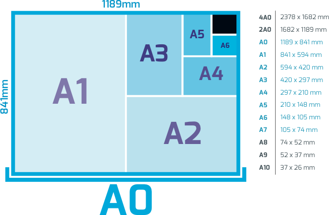
- FORMATOS NORMALIZADOS
- SERIE FORMATOS
ALARGADOS
- USOS ESPECIALES
- USOS ESPECIALES
- SERIA A
- SERIE PRINCIPAL
- A0= 841mm x 1189mm
- A2= 420mm x 594mm
- A4= 210mm x 297mm
- A0= 841mm x 1189mm
- SERIE PRINCIPAL
- SERIE B
- SERIE SECUNDARIA
- B0= 1000mm x 1414mm
- B2= 500mm x 707mm
- B4= 250mm x 353mm
- B0= 1000mm x 1414mm
- SERIE SECUNDARIA
- SERIE FORMATOS
ALARGADOS
- LINEAS NORMALIZADAS
- CLASIFICADAS SEGUN EL
PROPOSITO
EN EL DIBUJO
- LINEA GRUESA
- Contornos visibles
- Contornos visibles
- LINEA FINA
- Cotas, ejes cortos, linea de proyeccion
- Cotas, ejes cortos, linea de proyeccion
- GRUESA DE TRAZOS
- Contornos y aristas ocultas
- Contornos y aristas ocultas
- FINA DE TRAZOS
- Contornos ocultos, aristas ocultas
- Contornos ocultos, aristas ocultas
- FINA DE TRAZOS Y PUNTOS
- Ejes de revolucion y trayectorias
- Ejes de revolucion y trayectorias
- LINEA GRUESA
- CLASIFICADAS SEGUN EL
PROPOSITO
EN EL DIBUJO
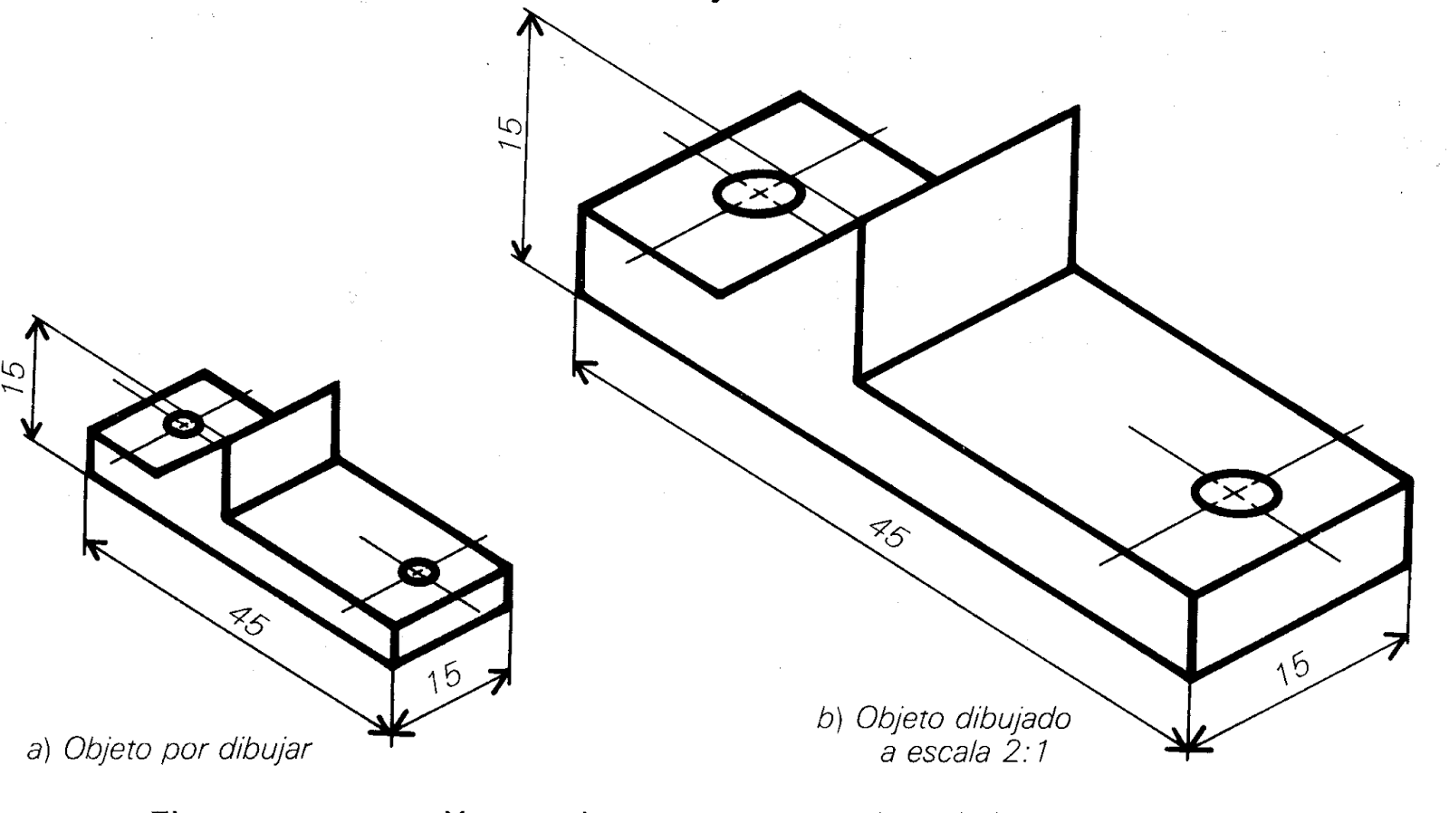
- ESCALAS
- Relacion entre el dibujo y la
realidad aplicada para cada una de
sus medidas.
- ESCALAS DE AMPLIACION
- Amplifican la realidad
- 2:1
- 5:1
- 50:1
- 2:1
- Amplifican la realidad
- ESCALAS DE REDUCCION
- Reducen la diemnscion real
conservando proporciones
- 1:2
- 1:5
- 1:200
- 1:2
- Reducen la diemnscion real
conservando proporciones
- DIBUJO : REALIDAD
- ESCALAS DE AMPLIACION
- Relacion entre el dibujo y la
realidad aplicada para cada una de
sus medidas.
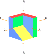
- VISTAS
- SEGUN LA UBICACION DEL
OBSERVADOR LOS OBJETOS
PUEDEN TENER 6 VISTAS
ORTOGONALES
- LAS VISTAS BASICAS SON
- ALZADO= FRONTAL
PLANTA = SUPERIOR
LATERAL
- ALZADO= FRONTAL
PLANTA = SUPERIOR
LATERAL
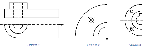
- LAS VISTAS ESPECIALES
- Vistas simetricas
- Representan una parte de la pieza,
tomando de referencia el eje de
simetria
- Representan una parte de la pieza,
tomando de referencia el eje de
simetria
- Vistas de detalle
- Permiten observar con
claridad partes del dibujo que
por su tamaño son dificiles de
interpretar
- Permiten observar con
claridad partes del dibujo que
por su tamaño son dificiles de
interpretar
- vistas locales
- Permite dinamizar el proceso de
representacion de cuerpos
simetricos
- Permite dinamizar el proceso de
representacion de cuerpos
simetricos
- Vistas giradas
- Vistas de posicion
- Vistas simetricas
- LAS VISTAS BASICAS SON
- El gran tamaño, y la
complejidad de algunas
representaciones hace
necesario aplicar:
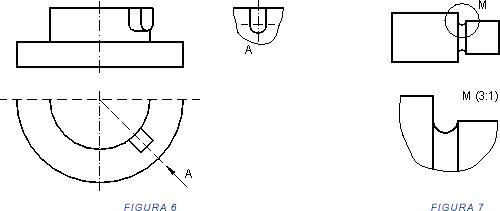
- Cortes
- Utilizados para detales internos
- Utilizados para detales internos
- Secciones
- Es la representacion de las
secciones producto del corte
- Es la representacion de las
secciones producto del corte
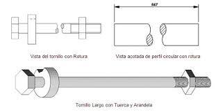
- Roturas
- Utilizadas para
representar objetos
largos
- Utilizadas para
representar objetos
largos
- Cortes
- SEGUN LA UBICACION DEL
OBSERVADOR LOS OBJETOS
PUEDEN TENER 6 VISTAS
ORTOGONALES
Media attachments
Want to create your own Mind Maps for free with GoConqr? Learn more.