Description
|
|
Created by Isaac Farias
over 9 years ago
|
|
Page 1
IP routing—the process of forwarding IP packets—delivers packets across entire TCP/IP networks, from the device that originally builds the IP packet to the device that is supposed to receive the packetThe complete end-to-end routing process relies on network layer logic on hosts and on routers. The sending host uses Layer 3 concepts to create an IP packet, forwarding the IP packet to the host’s default gateway (default router). The process requires Layer 3 logic on the routers as well, by which the routers compare the destination address in the packet to their routing tables, to decide where to forward the IP packet next.The router receives a frame, removes the packet from inside the frame, decides where to forward the packet, puts the packet into another frame, and sends the frame.
Page 2
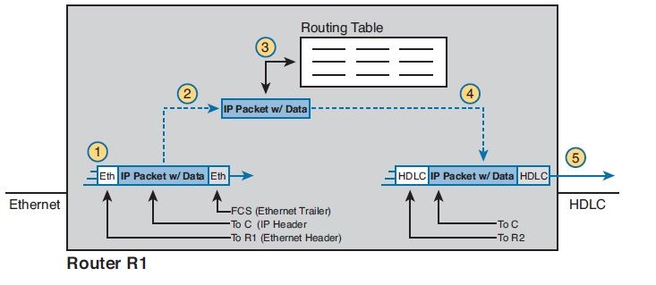
Router R1 processes the frame and packet as shown with the numbers in the figure, matching the same five-step process described just before the figure, as follows: 1. Router R1 notes that the received Ethernet frame passes the FCS check, and that the destination Ethernet MAC address is R1’s MAC address, so R1 processes the frame.2. R1 deencapsulates the IP packet from inside the Ethernet frame’s header and trailer.3. R1 compares the IP packet’s destination IP address to R1’s IP routing table.4. R1 encapsulates the IP packet inside a new data-link frame, in this case, inside a High- Level Data Link Control (HDLC) header and trailer.5. R1 transmits the IP packet, inside the new HDLC frame, out the serial link on the right.Routing Step 1: Decide Whether to Process the Incoming FrameRouting Step 2: Deencapsulation of the IP PacketRouting Step 3: Choosing Where to Forward the PacketNOTE Routes for remote subnets typically list both an outgoing interface and next-hop router IP address. Routes for subnets that connect directly to the router list only the outgoing interface, because packets to these destinations do not need to be sent to another router.Routing Step 4: Encapsulating the Packet in a New FrameRouting Step 5: Transmitting the FrameInternal Processing on Cisco Routers Potential Routing Performance Issues - The process of matching a packet’s destination address with the IP routing table can actually take a lot of CPU timeNow think about a router CPU that needs to search a list 100,000 entries long, for every packet, for a router that needed to forward hundredsof thousands of packets per second! And what if the router had to do subnetting math each time, calculating the range of addresses in each subnet for each route? Those actions would take too many CPU cycles. Cisco Router Fast Switching and CEF - Cisco routers used internal logic called process switching in the early days of Cisco routers, dating back to the late 1980s and early 1990s. Fast switching made a couple of optimizations compared to the older process-switching logic. First, it kept another list in addition to the routing table, listing specific IP addresses for recently forwarded packets. This fast-switching cache also kept a copy of the new datalink headers used when forwarding packets to each destination, so rather than build a new data-link header for each packet destined for a particular IP address, the router saved a little effort by copying the old data-link header.Cisco improved over fast switching with the introduction of Cisco Express Forwarding (CEF) later in the 1990s. Like fast switching, CEF uses additional tables for faster searches, and it saves outgoing data-link headers CEF organizes its tables for all routing table destinations, ahead of time, not just for some of the specific destination IP addresses. CEF also uses much more sophisticated search algorithms and binary tree structures as compared to fast switching. As a result, the CEF table lookups that replace the routing table matches take even less time than with fast switching. And it caches the data-link headers as well. Today, current models of Cisco routers, and current IOS versions, use CEF by default.
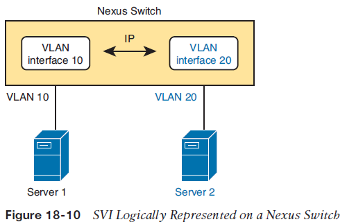
Cisco Nexus Switch Operations with RoutingA multilayer switch is essentially a switch at Layer 2 that has routing functionality.Multilayer switches traditionally have been built to give you the ability to have multipleVLANs on a given switch and route between them if needed without the need for an externaldedicated router.Switches use ASICs to provide forwarding in hardware to accelerate the process of packet switching and routing, in comparison tothe original routers, which did this primarily in software.The second major difference between multilayer and Layer 2 switches is based on how routing is implemented or configured on them. On a Layer 3 switch, you can implement a switched virtual interface (SVI) or a Layer 3 routed interface (sometimes referred to as a router port).The first thing to understand is how a Cisco Nexus switch implements the logical routed interface known as an SVI and when you would want to use it in you data center. Figure 18-10 shows what an SVI looks like logically in a Nexus switch
Page 3
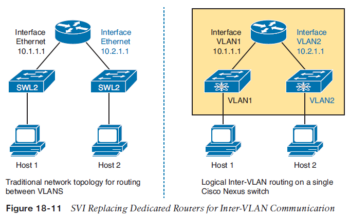
As you can see, the Nexus switch in Figure 18-10 creates a VLAN for both hosts to communicate then enables an interface for VLAN 10 and 20 that has IP connectivity enabled. The top layer of this figure is representative of a logical router that is created for each VLAN (10 and 20, respectively) and assigned an IP address. This allows for many Layer 2 interfaces to be part of either of these networks and also enables the Cisco Nexus switch to route between them if communication is needed using the SVI interfaces. In the past, when there were no multilayer switches like a Cisco Nexus switch, you had to attach separate physical routers to your switched network and send packets up to them to route between different networks, as shown in Figure 18-11.
Page 4
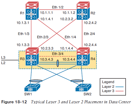
Now with Cisco Nexus switches being able to perform both routing and switching simultaneously, you can enable SVIs or logical routers on them and allow for inter-VLAN routing without having to go to another external device. The typical use case for this in the data center is at the distribution or access layer, where you need to do inter-VLAN routing and support many downstream Layer 2 networks at the same time, as shown in Figure 18-12.In Figure 18-12, we would enable SVIs on R3 and R4 for any Layer 2 networks below them or off of SW1 and SW2. This allows for multiple devices to join these networks by being assigned to a VLAN and for inter-VLAN communication to happen at R3 and R4.The question that now usually gets asked is this: “When do I use an SVI versus a routed interface?” We have answered this question already, but let’s now review when it might be good to use them and look at a few considerations when using an SVI or a routed interface.The SVI is most useful when we need to support Layer 2 and Layer 3 simultaneously for a given subnet. You’re probably wondering what that means. If you refer to Figure 18-12, in a typical data center design we have an aggregation layer where all the Layer 2 connected devices live, but we need to provide default gateways for them as dedicated routers normally would if connected to a switched network in the past. Using an SVI here lets us run Layer 2 protocols such as Spanning Tree Protocol (STP) and run a logical router that acts as the default gateway for a VLAN or many VLANs. (Each VLAN has its own logical router or SVI interface.) This enables us to add devices to this Layer 2 network and point them to their gateway (SVI or logical router) to talk to other networks.
Page 5
So, when should you use a routed interface? A routed interface is useful when you don’t need any Layer 2 devices on a routed segment, such as when you want to peer from a routing perspective with another router or multilayer switch. In this case, you create a small subnet (usually a /30) between the devices and dedicate an interface for peering, because no other devices will live on this segment except the peering routers, which do not need to support Layer 2 because we use routed interfaces for this connection.NOTE One benefit from using routed interfaces when dedicating them for router peering is that they provide faster downtime detection of a failed interface or link. If you are using SVI peering, it takes longer from the time the interface or link fails for the router to, in turn, shut down the SVI than it would if it were a routed interface.
Want to create your own Notes for free with GoConqr? Learn more.