Description
|
|
Created by Isaac Farias
over 9 years ago
|
|
Page 1
Chapter 21 Nexus Routing Protocol Configuration
Foundation TopicsThe Cisco Nexus switches have the capability to be enabled for IP Version 4 and 6 routing protocols; this chapter focuses on IPv4 routing protocol configurations. When implementing these protocols on a Cisco Nexus switch, it is important to understand the fundamentals of routing on any Cisco Layer 3 switch. First, two different types of interfaces can participate in Layer 3 operations. One is referred to as a routed interface, where you disable switching on this interface using the no switchport command and dedicate it for Layer 3 operations.
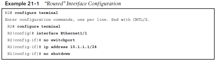
The second interface that can participate in Layer 3 operations is a switched virtual interface (SVI), Example 21-2 shows the enabling of an SVI on a Cisco Nexus Layer 3 switch. After configuring these two options, you then enable IPv4 routing protocols to enable participation with the routing protocol of your choice.
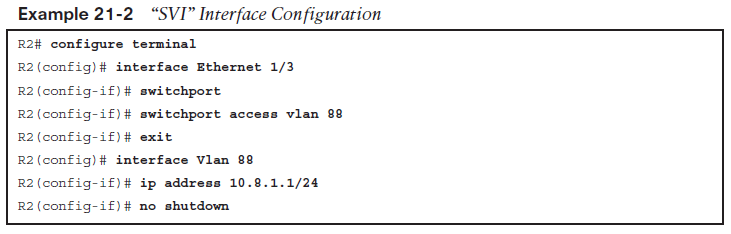
Another fundamental to note in NX-OS, which is different from previous Cisco operating systems, is that you enable the routing instance on each interface or SVI that you would like to have participating in the routing process. This is important to note for two reasons: ■ In older versions of IOS, when enabling IPv4 routing protocols, you would specify the networks under the router protocol tag, which in some cases enabled routing process for multiple interfaces, especially on Layer 3 switches that had an IP address in that subnet range. Why this is important is that in Layer 3 routing protocols, you want to minimize the amount of adjacencies per routing protocol to aid in the stability, recovery, and con vergence of the network. By enabling under the interface, you can be more granular on which interface/subnets will participate or be advertised to neighbors.■ The second benefit is that in earlier IOS versions, when you enabled a network statement under the routing process that covered multiple interface addresses, the router would also start sending hello messages out of those interfaces. To limit the number of neigh bor adjacencies, you would use the passive interface command to limit which interfaces would send hellos. NX-OS simplifies this because you enable the routing process only under the interfaces with their associated subnets; in turn, you only have to add the passive interface command under the interfaces you don’t want to form neighbor adjacencies on but would like their subnets advertised to neighbors.
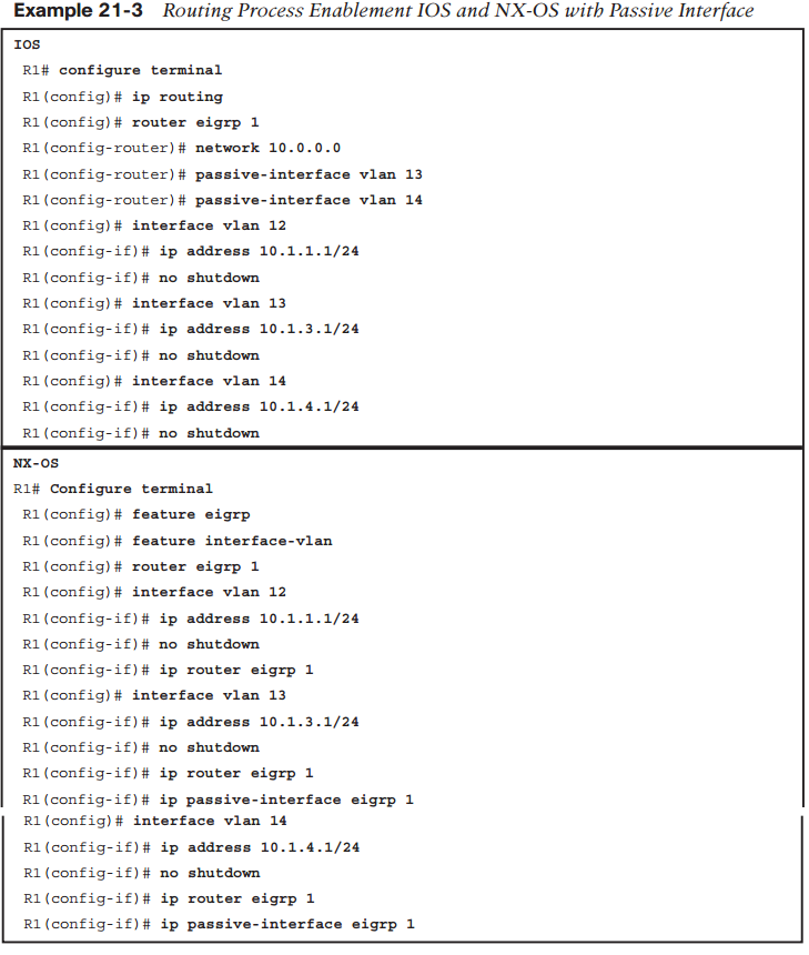
Before we get into our three different routing protocol configurations, we need to explore a common tool you will use to troubleshoot and verify routing in your network no matter what routing protocol you use, and this is the routing table. You have learned about this in previous chapters, but let’s spend some time looking at the routing table and what we need to look at to verify your networks are working the way you expect them to. Example 21-4 shows a sample routing table on a Nexus switch.
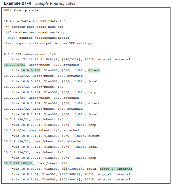
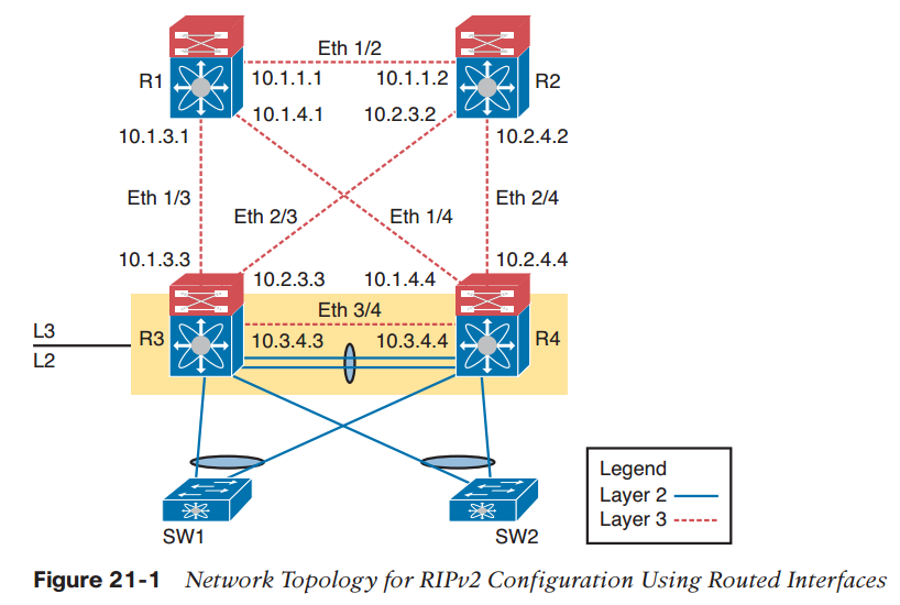
In the output, you see a couple of highlighted areas that are important to look at when you verify your networking by looking at the routing table. First, you can see the route high lighted in the top left (10.0.0.0/24), which is a destination you have the capability to route to. Just below, as part of the routing table output, you see that you can reach this network via 10.0.0.252 and that it is a direct route. A direct route means that you have an interface directly connected on this device that lives in that network. To see a network to which you have access that is not directly connected to this Cisco Nexus switch (see the route for 10.0.128.103/32 highlighted), this route actually can be reached through three different paths, and you see that the admin cost of 90 is associated, letting you know it is an EIGRP route.RIP Version 2 Configuration on NX-OSThis section describes how to enable RIPv2 (the default version on Cisco Nexus switches), validate configuration, and perform basic troubleshooting. Figure 21-1 shows routing between four Nexus switches—a topology common in today’s data centers. You will use this topology to configure RIPv2 in two ways: ■ RIPv2 enabled via routed interfaces ■ Based on SVI being enabled as the Layer 3 interface for routing protocol participation.
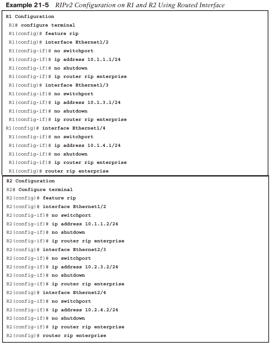
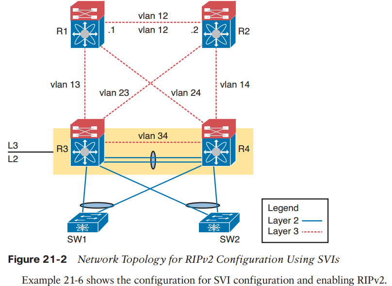
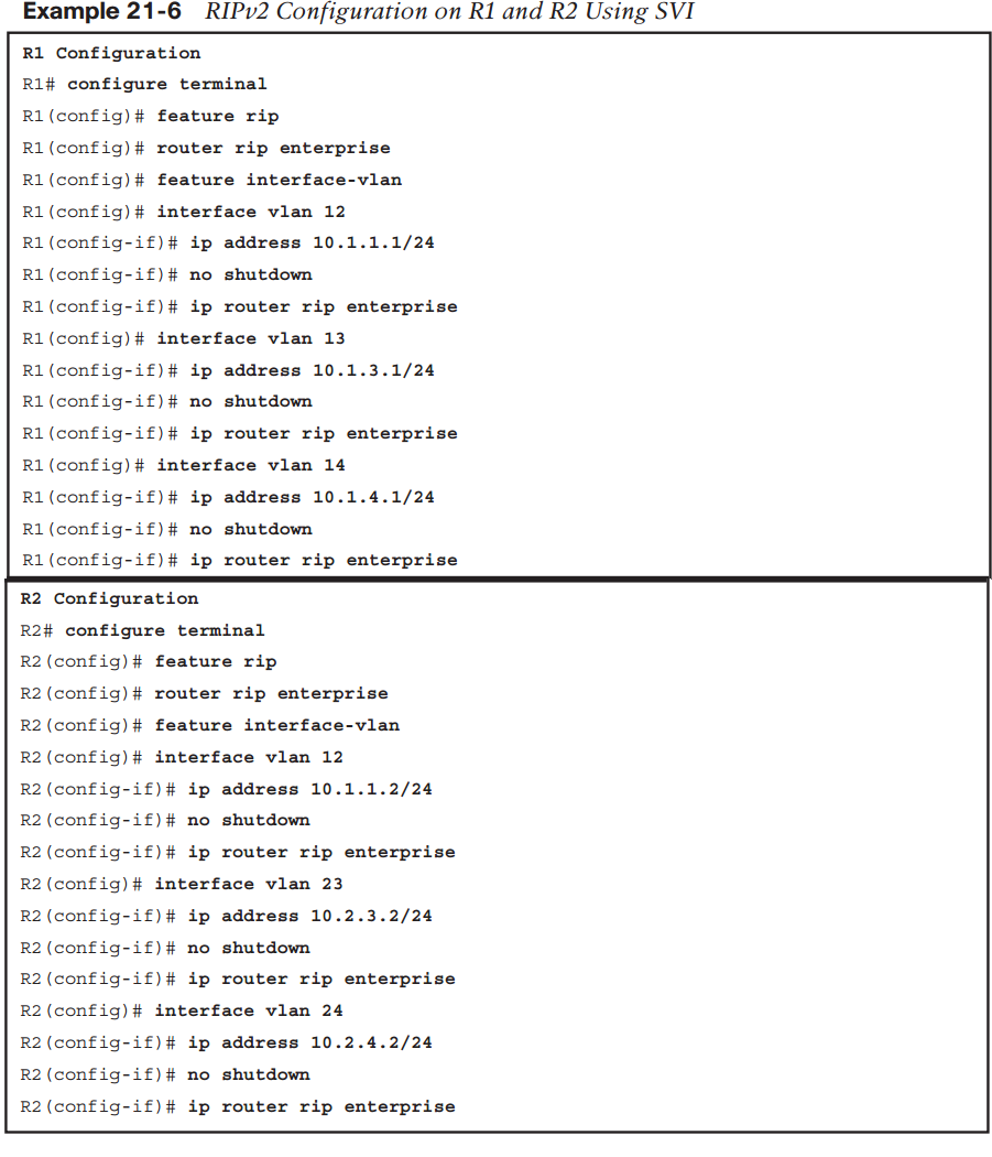
As shown in the configurations in Example 21-5, each Nexus, R1 through R4, would have similar configurations for feature rip being enabled globally, with no switchport under the physical interface to put the interfaces into a strict L3-only mode (no switching). From there, you enable the routing process for RIP using the ip router rip enterprise command . Also, you would need to enable the router rip instance-tag; this example uses enterprise as the instance tag to identify the routing process to be enabled on the interfaces.NOTE Nexus 7000 series switches by default have all physical interfaces in no switchport or Layer 3 mode, while Nexus 5000 series switches have switchport enabled on each physical interface by default.So far, you have learned how to configure RIPv2 on a Nexus Layer 3 routed interface. The next task is to learn how to do this using interface VLAN or switched virtual interface (SVI) at Layer 3. Figure 21-2 uses the same basic topology as Figure 21-1, but peers R1 and R2 over a VLAN using RIPv2.NOTE Nexus 5ks have all of the interface enabled or in a no shutdown state, while Nexus 7ks by default have them disabled or in a shutdown state. It is important to check this while configuring your 7k or 5k.
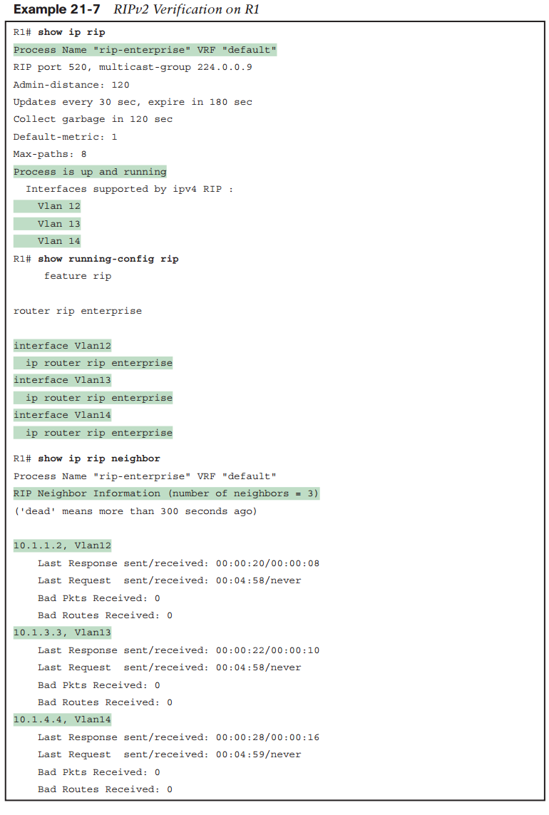
Finally, you need to verify that your RIP configuration is correct, followed by some basic troubleshooting for RIPv2 2 on Cisco Nexus switches. Example 21-7 uses show commands to validate that the neighboring Layer 3 Nexus switches are communicating with each other and learning routing via the RIPv2 routing protocol.
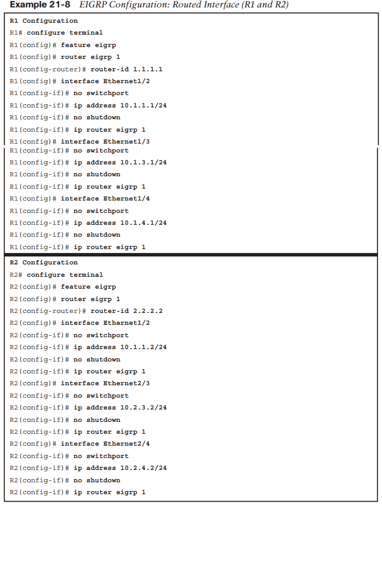
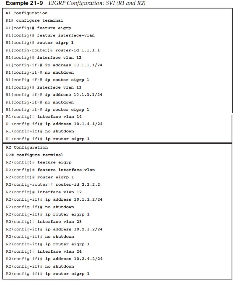
From the show ip rip command output, you can validate on the local Layer 3 switch which interfaces are enabled for IPv4 RIP, whether the process is enabled on the Layer 3 switch, as well as confirm the configured process name. From the show running-config rip command output, the highlighted items isolate what interfaces have been configured for the RIP process. show running-config rip is an important command for ensuring that you configured the instance-tag correct globally and on the interfaces you want enabled for RIP. The final show command in Example 21-6 is show ip rip neighbor, which enables you to see that the neighbors have come up, the IP addresses with which you are peering, and how many you have. If you see that you do not have the number of neighbors in comparison to the interfaces/SVI with which you have enabled RIP, this provides a good indication of which interfaces on R1 and the adjacent Layer 3 switch for which you need to validate the configuration.As you can see, using these three show commands individually and together, you can validate and troubleshoot your configurations of RIP on the Cisco Nexus switches. EIGRP Configuration on NX-OSEnhanced Interior Gateway Routing Protocol (EIGRP) is as the name says—an enhanced version of the original IGRP. EIGRP is sometimes referred to as an advanced version of a distance vector routing protocol because it brings some of the benefits of a link-state routing protocol but also has some characteristics of a standard distance vector routing protocol.This section of the chapter demonstrates the ways to configure EIGRP on SVIs and routed interfaces as well as how to verify/troubleshoot the configuration of EIGRP. Through this verification and configuration, you will be able to see why EIGRP is seen as an advanced distance vector routing protocol. Example 21-8 shows the configuration of EIGRP on NX-OS using the routed interface example based on Figure 21-1. Example 21-9 shows configuration of EIGRP on NX-OS using SVIs based on Figure 21-2.
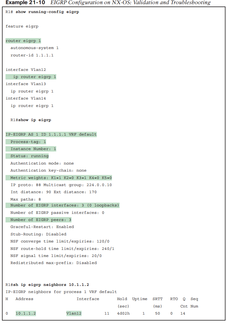
One new command that differs in the configurations for EIGRP is the use of the router-id x.x.x.x under the router eigrp 1 process. Router IDs are important for identifying the router with a unique identifier in the routing protocol; each router will have a unique router ID that can be manually configured or dynamically assigned based on a selection process. In NX-OS, the process for selecting the router ID is as follows:1. A router ID has been manually configured under the routing process (preferred).2. The highest local IP address is selected, and loopback interfaces are preferred.3. If no loopback interfaces are configured, use the highest IP address of a local interface.Example 21-10 showcases some show commands used to validate and troubleshoot the EIGRP configurations from Examples 21-8 and 21-9. As mentioned earlier in the RIP section, the validation is the same whether you use SVI or routed interface configurations. Example 21-10 shows three different show commands and their output for validating and troubleshooting.
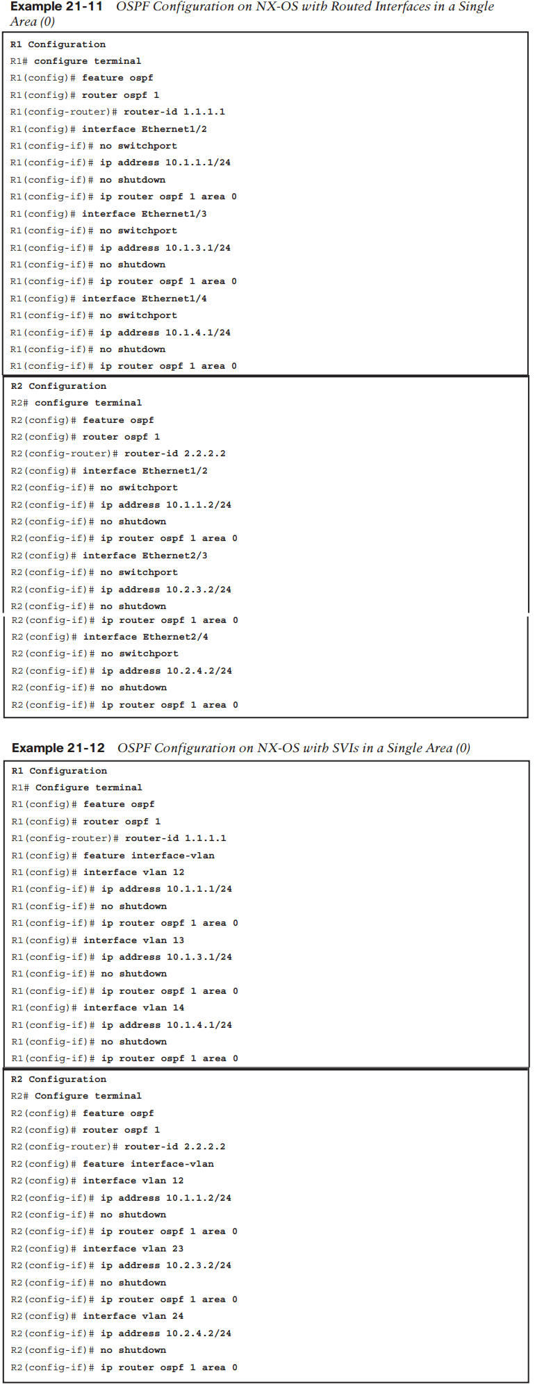
In the output for the SVI configuration in Example 21-9, you see three different show command outputs from R1, each of which needs to be looked at individually and together to help you make sure that you have configured the routing protocol correctly. Start by taking a look at the first show command and identify the key parts of the output that can help validate or troubleshoot your configurations. From the show running-config eigrp command , you see the configuration output of what you have configured in particular to EIGRP on this Nexus device. Notice that the EIGRP autonomous system ID of 1 is the same for the router eigrp 1 command as it is for the ip router eigrp 1 subinterface command. This tells youthat you have configured the correct EIGRP process on each interface for the global routing process, which is key to validating that your configuration is correct. You can execute these same commands on each Layer 3 switch to confirm correct configurations are in place.NOTE EIGRP uses what is known as an autonomous system ID. This number must match for the routers to form as neighbors. In our example, number 1 is the autonomous system number (between 1 and 65,535), which must be the same on all EIGRP-speaking routers in the network that would like to communicate and share routing information.The last two show commands, show ip eigrp and show ip eigrp neighbors, enable you to validate or troubleshoot that you have formed neighbor relationships with other Layer 3 switches and that they are communicating/sharing information. The highlighted output from show ip eigrp focuses on some key information. First, you can again validate that the process ID is configured correctly (also referred to as autonomous system ID if a numberis used), and you can also see the status as running. By default, EIGRP uses bandwidth and delay with K value modifiers to calculate this metric to choose the best route to install in the routing table (successor) for any given destination. We do not go deep into this calculation here, but it is important to note that K1 is the bandwidth modifier for calculation and K3 is the delay modifier for calculation, so by default in your output, you should see K1 and K3 set to 1 and all other K values set to 0.Finally, you see the number of neighbors (peers) and interfaces participating. Though these numbers for peers and interfaces do not always match, as in the case of peering with multiple neighbors on a local-area network over one interface, it can help you understand the peering and interface configurations. In the final output from show ip eigrp neighbors 10.1.1.2, you can validate that the neighbors are up, how long they have been up, their IP address, and the interface in which the peering happened. Note one final thing about EIGRP (which you can see in the outputs) that differentiates it from other distance vector routing protocols: its hello and update methodology.OSPF Configuration on NX-OSThe Open Shortest Path First (OSPF) Protocol is the final routing protocol to look at from a configuration perspective. In comparison to RIP and EIGRP, OSPF is considered a link-state routing protocol, and the following examples point out the differences in configuration, validation, and troubleshooting of this routing protocol from RIPv2 and EIGRP. Example 21-11 shows the configuration of a single area (0) with routed interfaces, andExample 21-12 explores configuring OSPF using SVIs for a single area (0).
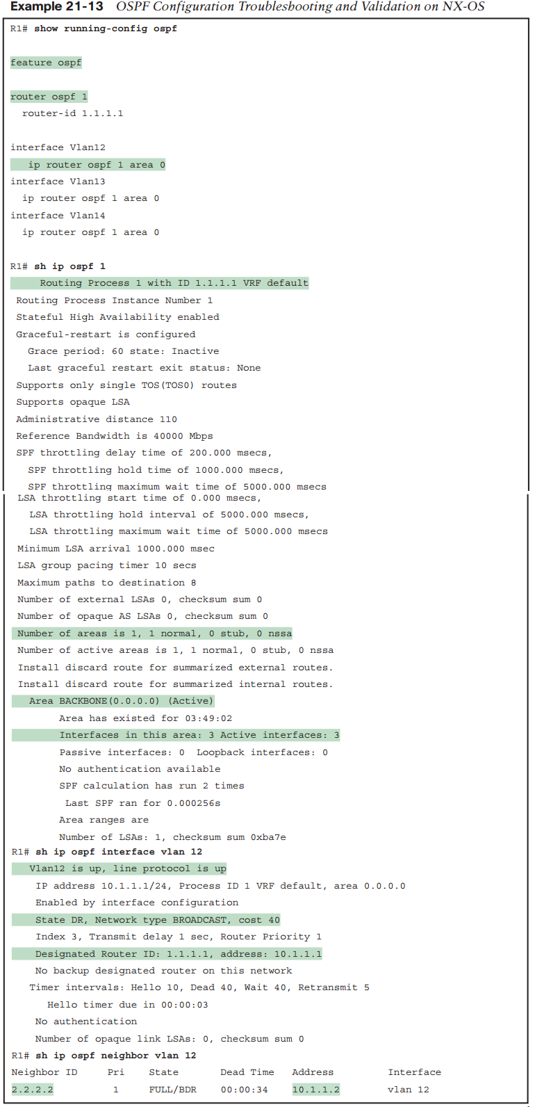
Both of these examples show one difference from the RIP and EIGRP examples: the area tag at the end of the ip router ospf 1 area 0 command. This is a key attribute to scaling OSPF implementations, so it is important to note that each interface on a router or Layer 3 switch can belong to the same or different areas based on the network design you are using.NOTE OSPF uses what is known as a process ID. This number does not have to match for the routers to form as neighbors. Unlike EIGRP, which uses this as an autonomous system number, the process ID for OSPF is locally significant. Next, look at the output of show commands to again validate and troubleshoot the configurations in Examples 21-11 and 21-12. Example 21-13 focuses on three show commands commonly used for troubleshooting and validating OSPF configuration on NX-OS.
The show running-config ospf command is the same command used with the other routing protocols, the difference being ospf at the end. This show command is your first step in verifying that the configuration you think you have implemented is as you think it should be. The highlighted parts of this first show command emphasize what you want to focus on—that your process ID for the router ospf command of 1 is the same implemented on each interface. In addition, you want to make sure that you have enabled the interfaces in the correct area (in this case, area 0, which you can confirm by finding ip router ospf 1 area 0 under the interfaces or SVIs). The show ip ospf 1 command is one of the more powerful commands as far as what it helps you to understand is happening on R1 with the OSPF configuration you have applied. The highlighted parts of this output show the router ID. If the router ID was not manually configured, it shows what was given through the selection process. Further down in the output, you see how many areas this router or Layer 3 switch is participating in. You also see how many associated interfaces are with a given area, which is important information to validate that you have configured the device correctly. The last show command, sh ip ospf interface vlan 12, is valuable to show how OSPF is running on each interface or SVI. The highlighted parts of this show command reveal whether the interface or SVI is physically up and also up from a line protocol perspective. In addition, it shows what has been chosen by default as an interface type by OSPF. In this case, it is broadcast interface, which you normally see on LANs or Layer 3 switch implementations. Because of the interface being broadcast, as you learned in Chapter 20, a designated router is needed in this OSPF area. As you can see, the last highlighted line of output shows the router ID of this designated router. The last output shows the neighbors what state they are in and their IP address.
Want to create your own Notes for free with GoConqr? Learn more.