
Mindmap
SIGNAL CONDITIONING
Inhalt der Mindmap
SIGNAL CONDITIONING
FILTERED
- Filtering depends on the elements that compose it, they are characterized by an input and an output, it is used to eliminate a frequency component of a signal from a frequency called cutoff frequency, characterized by a function H(w)
- According to their components, they are classified as passive, active, switched capacity and digital.
- According to their frequency response, they are classified as low-pass, high-pass, band-pass and band-reject filters.
- Types of filters
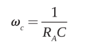
- Low-pass filter: attenuates unwanted frequencies, frequencies greater than Wc are attenuated according to a determined scale factor, it lets low frequencies pass and attenuates high frequencies according to the filter's behavior.
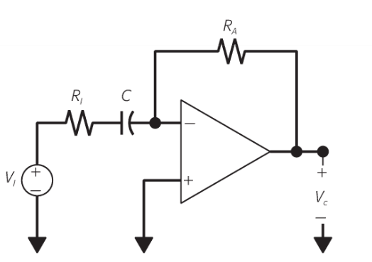
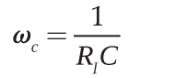
- High-pass filter allows the passage of frequencies higher than the cut-off frequency and therefore attenuates the lower ones. When the frequencies are low, the capacitor opens with voltage at the output. When they are high, it will behave like a short circuit and the output will be equal to the input.
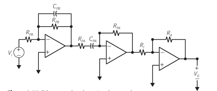
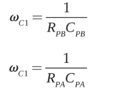
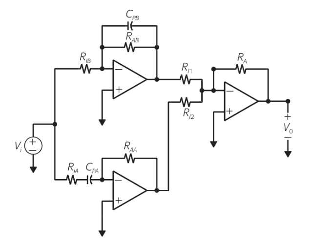
- Band-pass filter: Works with intermediate frequencies, allowing the passage of a frequency determined by a minimum and maximum frequency, they have a central frequency and two cut-off frequencies, which define the band that can pass, these filters are generally modeled as a low-pass filter in series with a high-pass filter and a final amplification stage.
- Band-reject filter: in this, unlike the band-pass filter, the voltage is measured in a capacitor-inductor pair, the cut-off frequencies are equal to the band-pass filter, when the frequency in the input signal is zero, the capacitor is open circuit and the inductor is short-circuited, however when the current is infinite, the elements change behavior contrary to that indicated above, the voltage is measured in an open circuit being equal to that of the input, at intermediate frequencies the voltage is attenuated and the output center frequency will be zero.
- Low-pass filter: attenuates unwanted frequencies, frequencies greater than Wc are attenuated according to a determined scale factor, it lets low frequencies pass and attenuates high frequencies according to the filter's behavior.
ANALOG TO DIGITAL CONVERSION
- Analog-to-digital converter, used to couple analog signals to digital circuits, usually a voltage or a current.
- They are the link between sensors and digital elements, the signal to be processed and the precision must be considered.
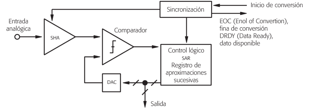
- Successive approximation ADC: allows high sampling speeds, first the signal is detected, at that moment the block that has SHA enters standby and all the bits are set to zero except the most significant bit, then the data in the SAR is an equivalent analog signal comparing it with the input, if the input signal is greater than what SAR has, the most significant bit is set to one otherwise zero and the procedure continues until the signals are equivalent
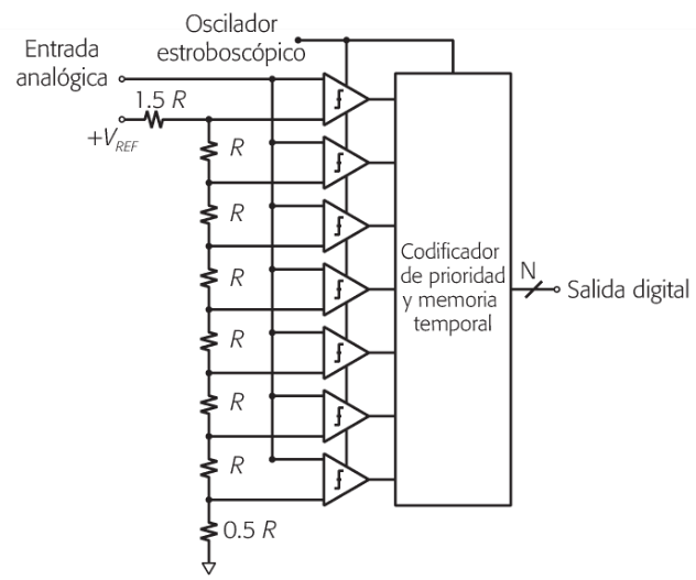
- Flash or parallel ADC: uses an arrangement of 2 to the N resistors and 2 to the N -1 comparators each comparator with reference voltage, thus, for a given signal the comparators work at the same time, so when the signal is greater than its voltage there is a one at the output otherwise it will be zero, when there is an output from the comparators it goes through the decoder, which gives a binary data.
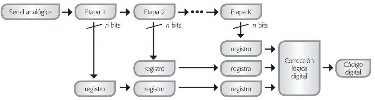
- A semi-parallel or multi-stage ADC is very fast and is used for 16 bits. It is divided into several stages, a partial conversion is performed, and the converted bits are rotated down and stored in a register. Each step has a SHA, in which the analog signal is then transferred to a flash ADC, connected to a DAC, and the DAC output is subtracted from the original signal, leaving a residual output and amplifying it. It is then digitally corrected, and the digital data is obtained.
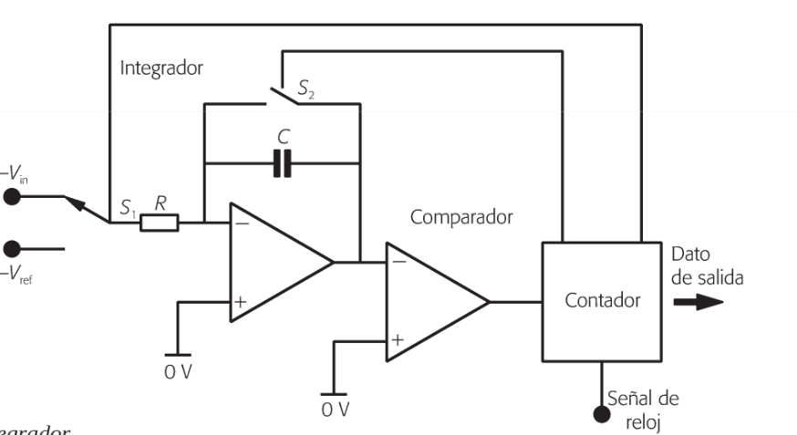
- ADC integrator or ramp is used in high precision systems with low frequency, the process is fulfilled in two stages, first the signal is in the integrator and remains there for a set time, in the second part it has a variable period proportional to the input signal, the counter is the one that distinguishes the voltages which is set to zero and starts counting in the second part and does this count until the voltage in the comparator reaches its highest value, the value of the count is the converted one.
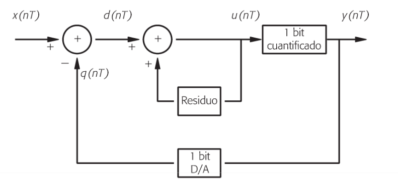
- Sigma-delta converters in this the input signal is sampled and a feedback signal from a one-bit DAC is subtracted from the input signal and what remains is accumulated by the integrator, what remains in the integrator is a signal that is quantified and a one-bit signal is created, the digital output signal determines the sign of the feedback, this is subtracted from the input signal to obtain an output bit and so on until the final data is obtained.
- Digital to analog converter: It is used to reconstruct an analog signal through a digital one that is in ones and zeros, the signal that is reconstructed is not exactly the original analog signal due to lack of information, but it is very similar and useful, this method is used between digital systems and can be actuators and there are different architectures for these tasks.
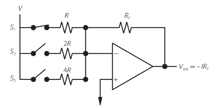
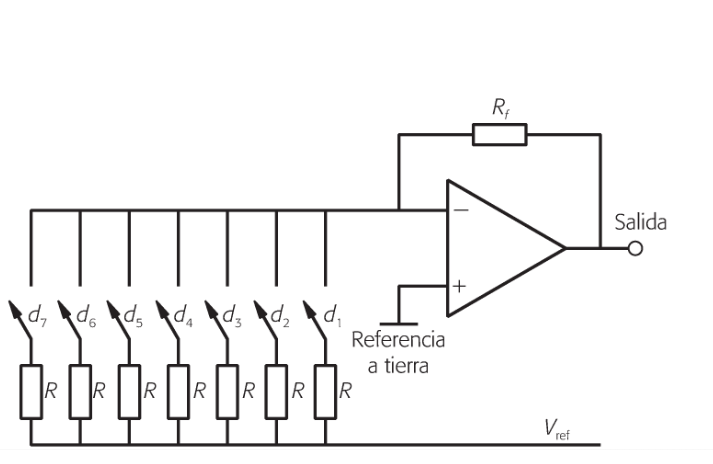
- Weighted resistor DAC uses an array of resistors whose values establish the scale factors for the binary data, then the voltages are added with an amplifier whose output is the analog signal.
- Sigma delta DACs operate in a similar way to analog-to-digital converters, the difference lies in the modulation, which is done digitally. The sensing and actuation system is used by both the ADC and DAC to achieve correct communication between the different elements.
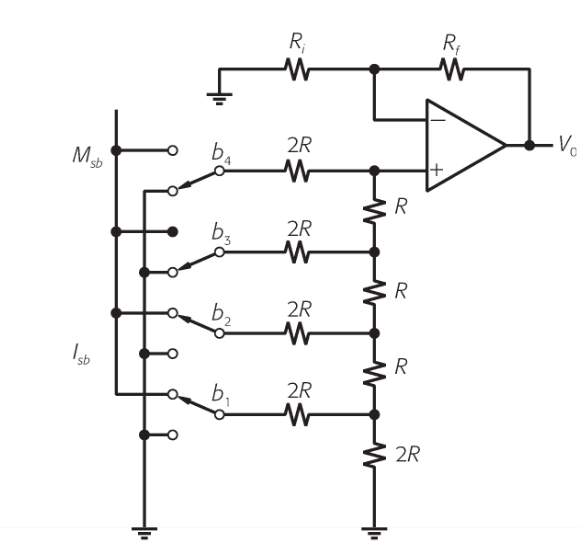
- DAC R-2R similar to the weighted resistors, but in this one the resistors are of only two values and switches that vary according to the value of the binary, if it is one the switch allows the voltage to pass and so the procedure continues
- DAC Thermometer the active bit code is read analogously to a mercury thermometer, a thermometer coding is used where each bit is gradually increased, if you have for example 10 bits you must have 10 resistors with their respective switch
- Weighted resistor DAC uses an array of resistors whose values establish the scale factors for the binary data, then the voltages are added with an amplifier whose output is the analog signal.
- Analog-to-digital converter, used to couple analog signals to digital circuits, usually a voltage or a current.
ELECTRICAL INSULATION
- There is no cable between the input and output, this signal is interrupted, the input passes to the output with an optical or magnetic type signal conversion, limiting unwanted input signals from passing to the output, the systems interact with each other input and output, but the voltage is different between them.
EXCITEMENT
- Some sensors require excitation to operate, some sensors with reluctance transduction principle require alternating current.
linearization
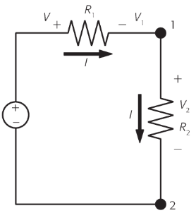
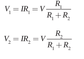
- Voltage divider: It is used for conditioning resistive type sensors, it allows obtaining different voltage levels with a single source, the response is linear only when the quotient of the resistance between the resistance of the sensor is equal to or greater than 100 and the resistance of the sensor varies linearly.
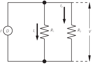
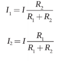
- Current divider, allows you to have different currents derived from the main one
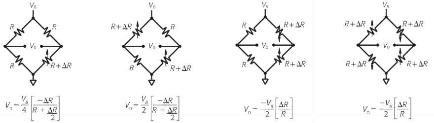
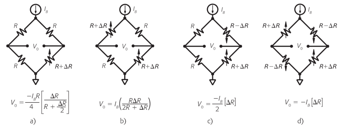
- Bridge circuits: use variations in resistance. A change in resistance translates into a change in voltage between two terminals. Elements with variable points are generally used.
- When there is a single variable element, it is typically used in temperature sensors or gauges. Two are used in pressure and flow elements or gauges. The element with all the variable resistances is used in load cells.
- They can also be powered by a power source as shown in the figure.
- These are known as Wheatstone bridges, consisting of four resistors arranged in a square, and their source can be voltage or current.
- Voltage divider: It is used for conditioning resistive type sensors, it allows obtaining different voltage levels with a single source, the response is linear only when the quotient of the resistance between the resistance of the sensor is equal to or greater than 100 and the resistance of the sensor varies linearly.
Amplification
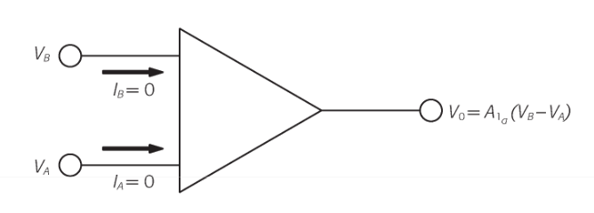
- Amplifier circuits, an amplifier circuit with two inputs and a single output, are used with external elements with or without feedback, and thus define the function it must perform.
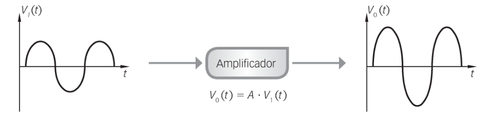
- It is a process in which the signal is increased, where there is a multiplication factor called A
- Types of amplifiers
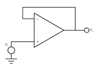
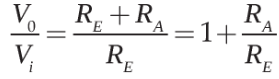
- follower amplifiers: The output voltage is equal to the input voltage, the input signal is not amplified, it is used not to amplify, but to cancel the load effects Vi=Vo; Vo/Vi=1
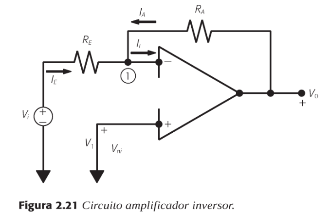
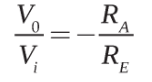
- Investors :With its configuration, it changes the sign of the input voltage.
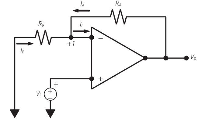
- non-investor:The output signal has the same input but without changing its phase, it is amplified without the signal being inverted.
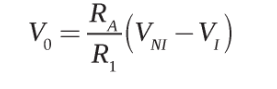
- A differential amplifier compares two voltages, allowing you to know when one changes.
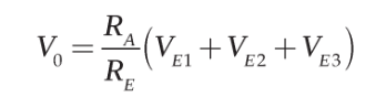
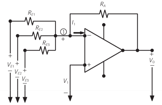
- Adders: These are used to add several signals and deliver a single output.
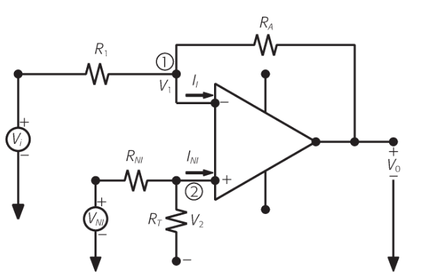
- Closed-loop differentials: These are amplifiers with negative feedback like open-loop amplifiers and allow the gain and performance of the circuit to be controlled.
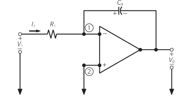
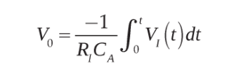
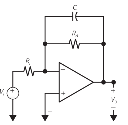
- Integrals, these have capacitors that make the output signal perform the integration operation, the output takes accumulation of the input over time.
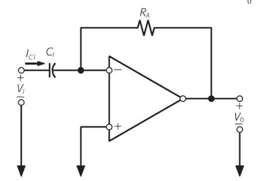
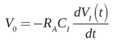
- Derivator performs the operation of deriving the input signal; the output is given based on the speed at which the input changes; it is used to show rapid changes in the input signal.
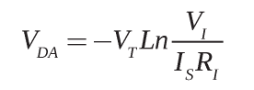
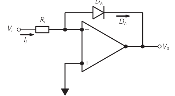
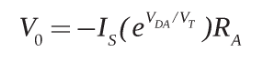
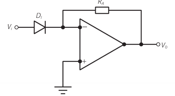
- Logarithmic: provides a logarithmic output, used when the signal varies over a range of many values, the amplifier compresses values and puts the output on a logarithmic scale
- Antilogarithmic: converts the logarithmic signal into a linear signal, giving a linear output depending on the input
- Implementation amplifier, used when very small voltage changes are required and where there is noise, it is generally found in integrated circuits, it amplifies very weak signals, especially in control environments
- follower amplifiers: The output voltage is equal to the input voltage, the input signal is not amplified, it is used not to amplify, but to cancel the load effects Vi=Vo; Vo/Vi=1
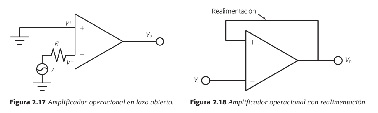
- All configurations are based on the operational amplifier, with two inputs and one output
- There are open loop and feedback amplifiers
Corona, L., Abarca, G., y Mares, J. (2019). Sensores y Actuadores: Aplicaciones con Arduino - 2a edición. (pp. 37-68). Grupo editorial Patria. https://elibro-net.bibliotecavirtual.unad.edu.co/es/ereader/unad/121284?page=52
Bilder und Dateien der Mindmap
Informationen
- Beschreibung
- Mindmap am SIGNAL CONDITIONING, erstellt von CINDY SANCHEZ am 22/03/2025.
- Erstellt von
- CINDY SANCHEZ
- Aufrufe
- 5
- Bewertung