15769373
Description
Flashcards by ASH BALDWIN, updated more than 1 year ago
|
|
Created by ASH BALDWIN
about 7 years ago
|
|
| Question | Answer |
| Building Thermal Equilibrium | - radiation loss - evaporation loss - conduction loss - ventilation loss - internal heat contribution - convection - radiation |
| BUILDING INSTANTANEOUS HEAT LOSS CALCULATION | ENVELOPE: HL(wall): BTUH = A x U x theta T PERIMETER/BASEMENT LOSS: HL(perimeter): BTUH = P (linear ft) x N BTUH/LF (N from table) VENTILATION LOSS: HL(infiltration): BTUH(sens) = 1.08 x CFM x theta T |
| PRIMITIVE HEATING - OPEN FIRES | RADIANT TRANSFER OF HEAT TO ENVIRONMENT |
| STOVES (IMPROVEMENT...WHY?) | improvement by sealing off the FIREBOX or COMBUSTION CHAMBER and "EXCHANGING" the heat of combustion of the fuel by radiation, conduction, and convection to another medium (typic. air) |
| STOVES: SEALED WOOD STOVES: | STOVES: - stone - brick - tile SEALED WOOD STOVES -cast iron - welded steel |
| COMBUSTION (OCCURS WHEN...) | COMBUSTION occurs when a FUEL reacts CHEMICALLY with ATMOSPHERIC OXYGEN to RELEASE HEAT. -fuels are typically hydrocarbons (molecules composed of almost exclusively carbon and hydrogen atoms) |
| COMBUSTION REACTION (RESULTS IN...) | COMBUSTION REACTION results in production of CARBON DIOXIDE (CO2) and WATER (H2O) |
| HEAT VALUE (LVH) IN BTU/UNIT (what is it?) | the amount of POTENTIAL HEAT released in combustion depends on the STRUCTURE OF THE FUEL MOLECULES. each fuel has its unique HEAT VALUE (LVH) in BTU/unit |
| IN ACTUAL HEATING EQUIPMENT (WOOD STOVES, BOILERS, FURNACES) COMBUSTION IS NOT 100 % EFFICIENT. WHAT IS DESIGN OF COMBUSTION CHAMBER FOR OPTIMUM EFFICIENCY? | optimum efficiency: combustion chamber of heating equiptment must allow for right MIXING of FUEL and AIR, and bring SUFFICIENT IGNITION TEMPERATURE to combustion zone. |
| COMBUSTION EFFICIENCY WORKS BEST IF: | combustion works best for fuels that are already VAPORIZED (natural gas). |
| LIQUID FUELS MUST BE... | ...ATOMIZED INTO SMALL DROPLETS to mix with AIR. |
| SOLID FUELS MUST BE... | ...Heated sufficiently to vaporize at the point of IGNITION VISIBLE SMOKE EVIDENCE OF UNBURNED FUEL. |
| MOST EFFICIENT COMMERCIALLY AVAILABLE BOILERS AND FURNACES USE... | LATENT HEAT OF VAPORIZATION....to reach efficiencies above 90%. |
| CONVENTIONAL HEATING EQUIPTMENT | the WATER VAPOR goes “UP THE CHIMNEY”, and the heat energy that converts the COMBUSTION WATER to VAPOR is lost with the other flue gases. |
| CONDENSING BOILERS AND FURNACES | flue gases COOL enough that WATER VAPOR condenses out of the FLUE GASES, and the latent heat of vaporization (970 BTU/lb.) is recovered in the heat exchanger. *This process adds a 5-10% increase in the heat energy available to heat the building from a given amount of fuel. |
| CENTRAL HEATING | heating engine needs to transfer the heat it produces to a medium that can be safely and effectively conveyed to all parts of the building. Typically, this heat transfer MEDIUM is WATER (or STEAM) or AIR. |
| HEATING PLANT TYPE BOILER: | equipment that exchanges combustion HEAT to a LIQUID (WATER) *combustion of hydrocarbons fuels |
| HEATING PLANT TYPE FURNACE: | equipment that exchanges combustion HEAT to AIR *combustion of hydrocarbons fuels |
| HEATING PLANT COMPONENTS: | - burner/grate - combustion chamber/firebox - HEAT EXCHANGER - draft inducer - flue or vent |
| COMBUSTION EFFICIENCY: | % OF POTENTIAL ENERGY OF FUEL CONVERTED |
| HEAT EXCHANGER EFFICIENCY: | % OF CONVERTED ENERGY TRANSFERRED |
| THERMAL EFFICIENCY (Et) = | COMBUSTION EFFICIENCY x HEAT EXCHANGER EFFICIENCY Et = E(combustion) x E(exchanger) Et = 1 - (flue gas losses/Heat Value of Fuel) |
| FLUE GAS LOSSES INCLUDE... | FLUE GAS LOSSES INCLUDE.....DRY flue Gas, incompletely BURNED fuel, and WATER VAPOR. *where there is smoke, there is waste |
| HEAT GAIN | OPAQUE ENVELOPE: HG: BTUH = A x U x delta T (or ETD) GLAZED ENVELOPE: HG(glass-rad): BTUH = A(grade area) x SHGF(each surf) x SHGC(glasS) x SC(ex. x int) *BTUH = A x SHGF x SHGC x SC |
| HEAT GAIN | INTERNAL GAINS: HG(lights): BTUH = W(lighting loads) x 3.412 BTUH/W HG(occupants-sens): BTUH = N(occupants) x BTUH(sens)/person |
| HEAT GAIN | VENTILATION GAINS: HG(ventilation-sens): BTUH(sense) = 1.08 x CFM x delta T HG(ventilation-lat): BTUH(lat) = 4840 x CFM x delta W |
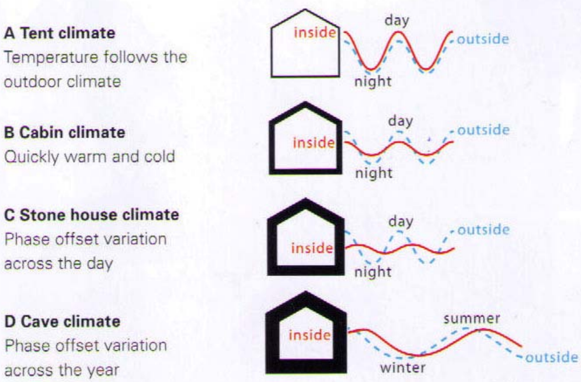
| COOLINGS STRATEGIES DEPEND ON.... | COOLINGS STRATEGIES DEPEND ON.... CYCLIC PHASE CHANGE as a mechanism for extracting heat from the local environment. |
| 2nd LAW OF THERMODYNAMICS | heat only flows from higher levels to lower levels. |
| COLD SINK: | COLD SINKs are at LOWER temperature than AMBIANT environmental temperature of the building and its occupants, SO the HEAT will flow from occupants, building, ambient air to COLD SINK *THIS PROCESS IS CALLED HEAT REJECTION AND IT TAKES PLACE IN A HEAT EXCHANGER. |
| NATURAL COLD SINKS: | - ICE STORED FROM WINTER - COOL AIR MASSES - COOL BODIES OF WATER - MASS OF THE EARTH (55 DEGREES BELOW 10 FT) |
| REFRIGERATION: | utilizes PHASE CHANGE of certain materials (refrigerants) to first ABSORB interior heat by EVAPORATION w/o increasing their TOTAL HEAT CONTENT so they can REJECT HEAT to environment at AMBIENT EXTERIOR TEMPERATURE before RE-CONDENSING. |
| ABSORPTION CYCLE: (refrigerant phase change by ABSORPTION) | - uses ADDITION OF HEAT and ABSORPTIVE CATALYST to facilitate the evaporation of the REFRIGERANT so it can REJECT LATENT HEAT OF VAPORIZATION when it LATER CONDENSES AT AMBIENT TEMPERATURES |
| MECHANICAL CYCLE: (refrigerant phase change by PRESSURIZATION) | - uses additional mechanical (usually electrical) energy to COMPRESS the HOT REFRIGERANT VAPOR so it can REJECT LATENT HEAT OF VAPORIZATION to ex. env. when it LATER CONDENSES AT AMBIENT TEMPERATURES |
| ABSORPTION CYCLE: (refrigerant phase change by ABSORPTION) | + HEAT & ABSORPTIVE CATALYST --> facilitate EVAPORATION OF REFRIGERANT *RARELY USED |
| MECHANICAL CYCLE: (refrigerant phase change by PRESSURIZATION) | + MECHANICAL ENERGY --> COMPRESS HOT REFRIGERANT *USUALLY USED (A.K.A. DX (DIRECT EXPANSION) CYCLE) |
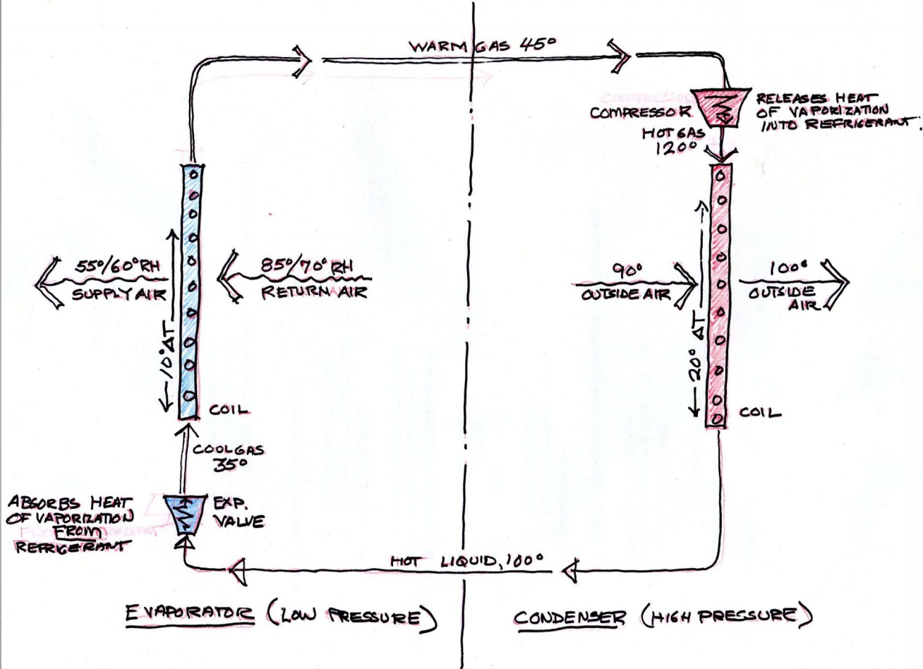
| REFRIGERATION: MECHANICAL CYCLE | COMPRESSOR 120 F --> COMPRESSED GAS --> CONDENSER (COOL IN, HEAT OUT) 100 F --> EXP VALVE --> 35 F EVAPORATOR (HEAT IN, COOL OUT) --> 45F --> COMPRESSOR |
| REFRIGERATION: MECHANICAL CYCLE | |
| REFRIGERATION COMPONENTS: - CONDENSOR | the component in which the HOT refrigerant CONDENSES to a LIQUID, rejecting latent heat of vaporization to the exterior environment. |
| REFRIGERATION COMPONENTS: - EVAPORATOR | The component in which the COLD refrigerant EVAPORATES to a GAS absorbing the latent heat of vaporization from the interior environment. |
| REFRIGERATION COMPONENTS: - REFRIGERANT | a medium whose phase change characteristics allow it to exist as a VAPOR and as a LIQUID within a controlled temperature range (ab. 30° F to 130° F). |
| REFRIGERATION COMPONENTS: - COMPRESSOR | a mechanical device used to COMPRESS vaporized refrigerant to LIQUID |
| REFRIGERATION COMPONENTS: - EXPANSION VALVE | a valve which maintains the COMPRESSION of the refrigerant in the CONDENSOR component until the refrigerant enters the evaporator component. |
| REFRIGERATION COMPONENTS: - HEAT EXCHANGER | a A physical arrangement of components which allows the exchange of heat by CONDUCTION between two separate mediums. rate of exchange is proportional to ∆T of the mediums. Both the the EVAPORATOR and CONDENSOR components are heat exchangers (coils). |
| CONDUCTION | the transfer of energy (heat of electric charge) through a substance. energy/heat is transferred form molecule to molecule by direct contact |
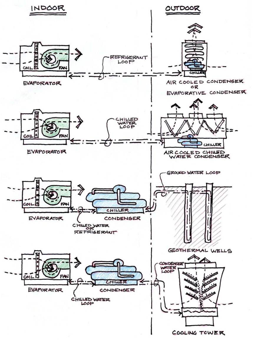
| AIR COOLED DX SPLIT SYSTEM (DIRECT EXPANSION AIR CONDITIONING) | - OUTDOOR AIR-COOLED CONDENSER - indoor REFRIGERANT evaporator COIL with FAN (ducted or ductless) |
| AIR COOLED DX SPLIT EVAPORATIVE SYSTEM: (DIRECT EXPANSION AIR CONDITIONING) | - OUTDOOR AIR-COOLED EVAPORATIVE CONDENSER - indoor REFRIGERANT evaporator COIL with fan (ducted or ductless) |
| AIR COOLED CHILLED WATER SPLIT SYSTEM: | - OUTDOOR AIR-COOLED CONDESNOR producing CHILLED WATER - indoor WATER EVAPORATOR coil with fan (ducted) |
| WATER COOLED CONDENSER with GEOTHERMAL WELLS: | -OUTDOOR OPEN-LOOP or CLOSED-LOOP GEOTHERMAL WELLS - INDOOR WATER COOLED CONDENSOR PRODUCING CHILLED WATER OR REFRIGERANT INDOOR WATER OR REFRIGERANT EVAPORATOR COULD WIHT FAN (DUCTED) |
| WATER COOLED CONDENSER with COOLING TOWER: | -Outdoor Open-Loop or Closed-Loop Cooling Tower -Indoor Water Cooled Condenser producing Chilled Water - Indoor WATER Evaporator Coil with Fan (Ducted) |
| COOLING PLANT CONFIGURATIONS | |
| Coefficient of Performance (COP): | The ratio of heat produced in BTU to the energy required to drive the refrigeration (or heating) process in BTU * For heating equipment, the COP is equal to the Thermal Efficiency (Et). |
| Energy Efficiency ratio (EER): | The ratio of heat produced in BTU to the input (site) energy in watts at a given operating condition. (EER is 3.413 x COP) |
| Seasonal Energy Efficiency ratio (SEER): | The ratio of heat produced in BTU to the input (site) energy in watts averaged over an entire cooling season rather than at a selected operating condition. SEER slightly higher than EER |
| NOTE: | COP and EER ratings do not take into account the thermal efficiency of the production of source electrical power, usually about 30%. |
| COP Ranges for Cooling Plant Equipment: | EER/3.412 [x .30] = COP |
| AIR-COOLED CONDENSERS: | - Noisy - Need outdoor free air; Usually site mounted or roof mounted - Architectural screening desirable. |
| COOLING TOWERS: | - Big, Tall, Heavy, Noisy, Water Spray - Need outdoor open air; difficult to conceal or screen |
| CHILLERS: | - Big, Heavy, Very Noisy - Require expensive indoor space; maintenance clearances - Acoustical isolation (air-borne sound, vibration) a necessity |
| HVAC: Comfort Variables: THERMAL FACTORS: | - Sensible Temperature (DBT) - Moisture (WBT) - Mean Radiant Temperature (MRT) - Air Velocity (FPM) |
| HVAC: Comfort Variables: AIR QUALITY (AQ): | - Particulates (Filtering) - Oxygen (O2) - Carbon Dioxide (CO2) |
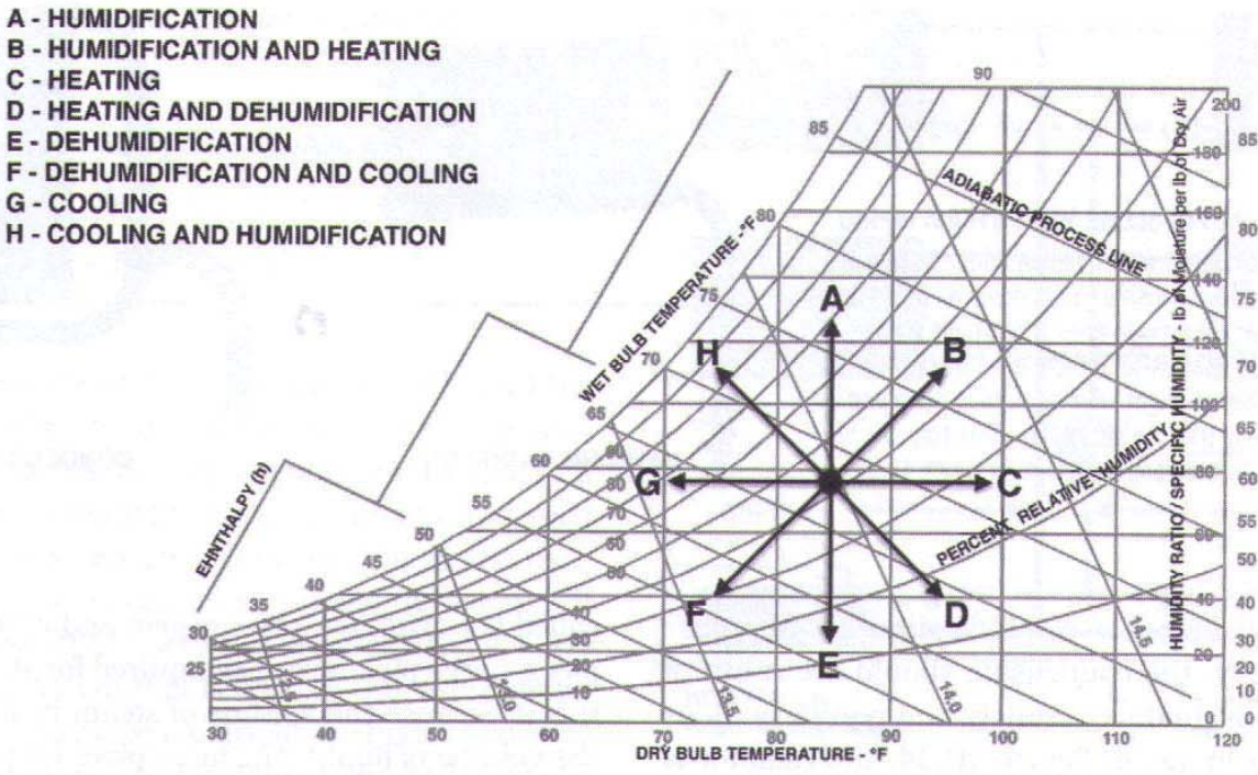
| Psychometric impacts: | |
| HVAC SYSTEM COMPONENTS HEATING: | - Combustion/Heat Source (boiler, furnace, solar collector)[fuel or insolation] - Heat Exchange Medium (hydronic (water) or air) - Circulation Device (pump, fan) [electricity] - Circulation Conduits: Pipes or Ducts - Terminal Device (radiator, convector, radiant panel, heating coil, grille) |
| HVAC SYSTEM COMPONENTS VENTILATION: | - Fresh Air(FA)/Outside Air (OA) Intake - Circulation Device: (gravity, fan) [electricity] - Exhaust/Vent - Terminal Device (diffuser, grille, window sash, louver) |
| HVAC System Components AIR CONDITIONING: | - Condenser/Heat Rejection [electricity, typically] - Evaporator/Cooling Coil - Exchange Medium (air or hydronic (water) ) - Circulation Device (pump, fan) [electricity] - Circulation Conduits: Ducts or Pipes - Terminal Device (diffuser, grille, radiant panel, cooling coil) |
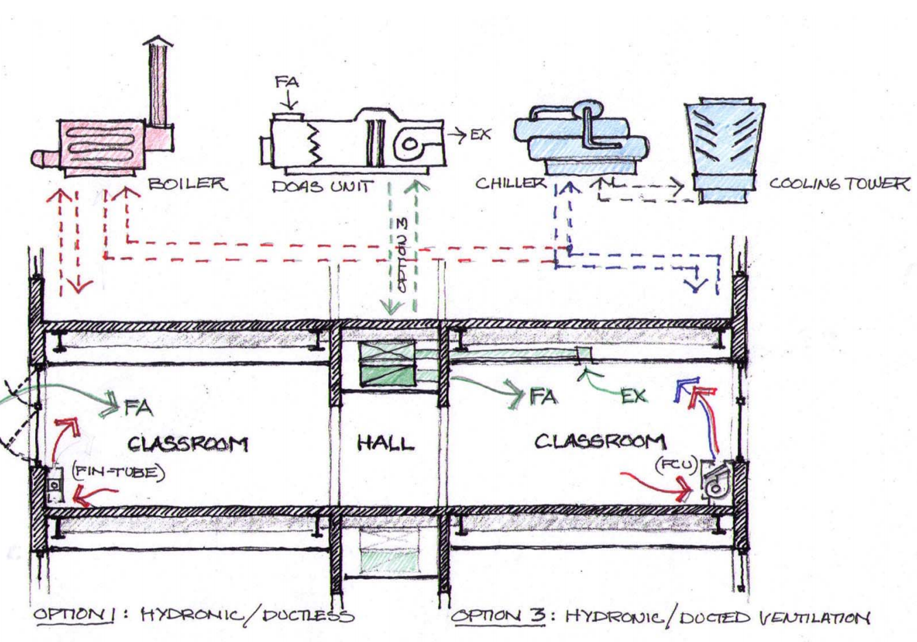
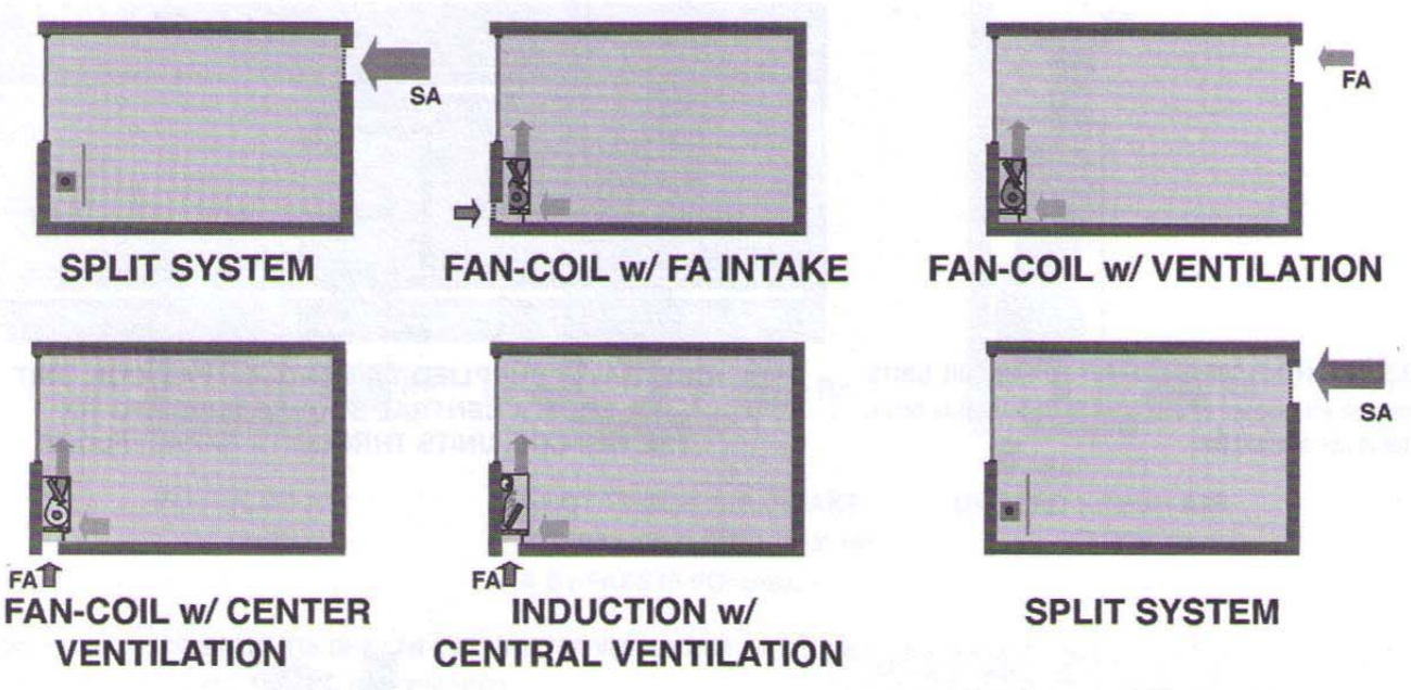
| Conventional HVAC System Types: | - OPTION 1: Hydronic/Ductless: DBT, MRT - OPTION 2: Hydronic/Local Exhaust Duct: DBT, WBT, FPM, MRT and AQ - OPTION 3: Hydronic/Ducted Ventilation: DBT, WBT, FPM, MRT and AQ. - OPTION 4: Hydronic/Ducted: DBT, WBT, FPM, and AQ - OPTION 5: DX/Ducted (RTU’s, Split Sys., Heat Pump): DBT, WBT, FPM, and AQ |
| OPTION 1: Hydronic/Ductless: DBT, MRT | - Heating: Central Boiler + Fin-tube/Radiators/Radiant Panels - Ventilation: Operable Windows - Cooling: N/A (or Window AC DX Unit) |
| OPTION 2: Hydronic/Local Exhaust Duct: DBT, WBT, FPM, MRT and AQ. | • Heating: Central Boiler + Fan Coil Units (FCU) • Ventilation: FCU FA Intake and Local Exhaust Fans • Cooling: Central Water Chiller + Fan Coil Units (FCU) |
| OPTION 3: Hydronic/Ducted Ventilation: DBT, WBT, FPM, MRT and AQ | • Heating: Central Boiler + Fan Coil Units (FCU) • Ventilation: Central Ventilation/Exhaust Unit (DOAS) • Cooling: Central Water Chiller + Fan Coil Units (FCU) |
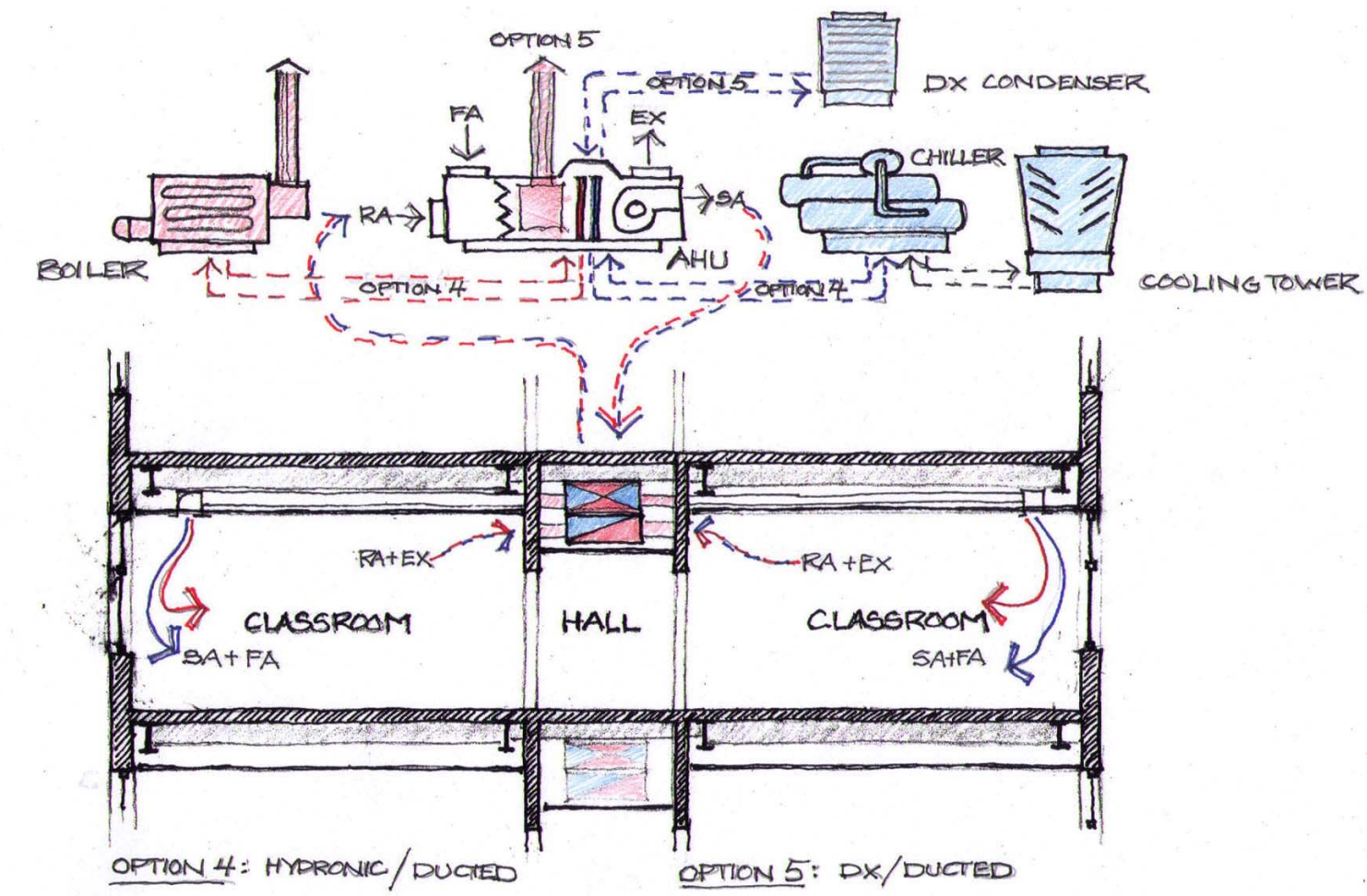
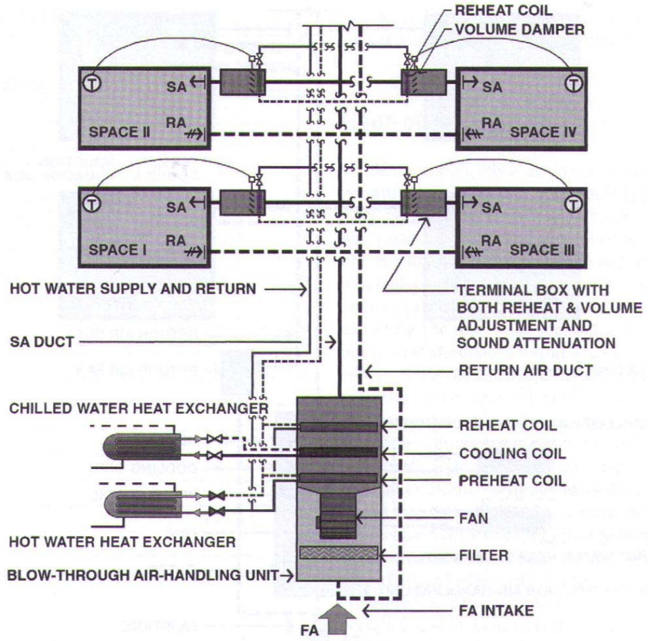
| OPTION 4: Hydronic/Ducted: DBT, WBT, FPM, and AQ | • Heating: Central Boiler + Zoned Air Handling Units (AHU’s) w/ Hot Water Coil • Ventilation: Zoned Air Handling Unit (AHU) with FA and Exhaust (Economiser) • Cooling: Central Water Chiller + Zoned Air Handling Units (AHU’s) w. Chilled Water Coil |
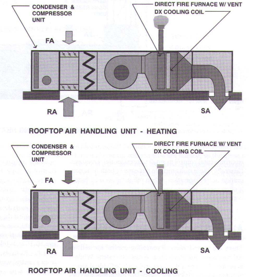
| OPTION 5: DX/Ducted (RTU’s, Split Sys., Heat Pump): DBT, WBT, FPM, and AQ | • Heating: Zoned Air Handling Units (AHU’s) with Gas or Electric Furnace • Ventilation: Zoned Air Handling Unit (AHU) with FA and Exhaust (Economiser ) • Cooling: Zoned Air Handling Units (AHU’s) with DX Coil and Condensing Unit |
| HVAC OPTIONS 1 AND 3 | |
| HVAC OPTIONS 4 AND 5 | |
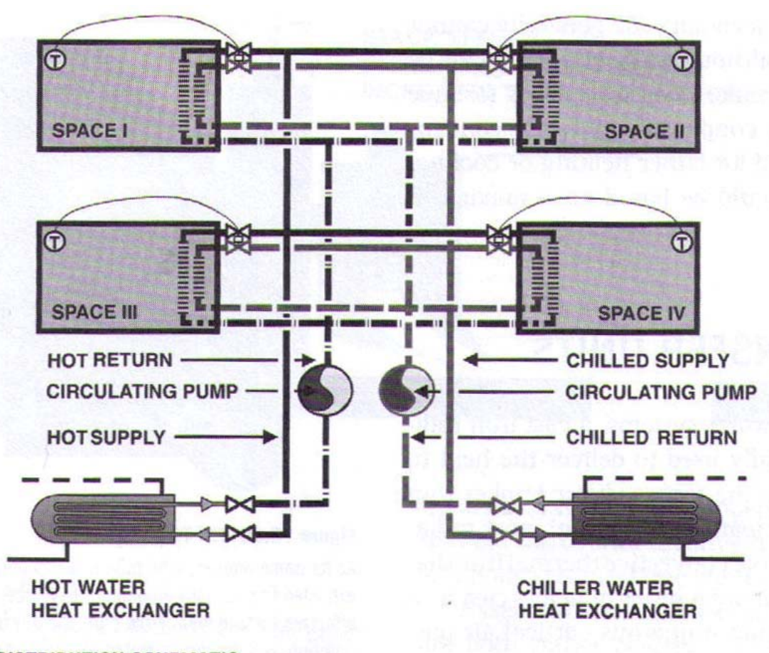
| Hydronic (Ductless) Systems: 1. PIPING CONFIGURATIONS: | • Two-Pipe Systems • Three-Pipe Systems • Four-Pipe Systems |
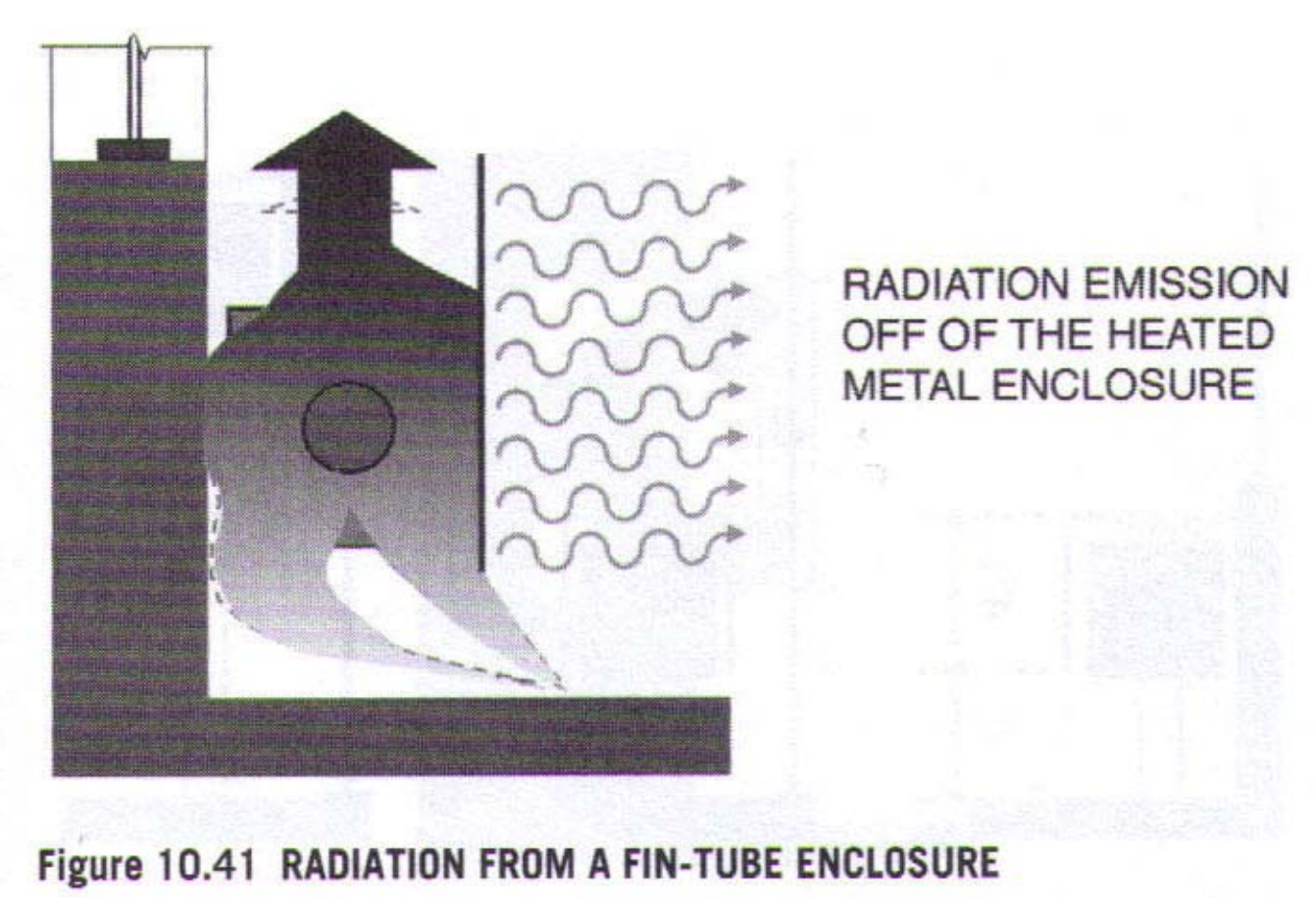
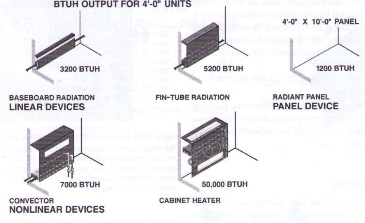
| Hydronic (Ductless) Systems 2. RADIANT/CONVECTIVE TERMINAL DEVICES: | • Cast Iron Radiators • Cast Iron Baseboard • Steel Radiators • Finned-Tube Radiators |
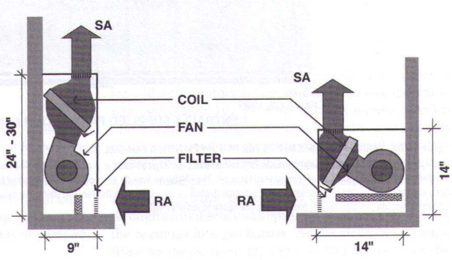
| Hydronic (Ductless) Systems 3. CONVECTIVE TERMINAL DEVICES: | Fan-Coil Units |
| Hydronic Systems: Four‐Pipe Distribution System | |
| Hydronic Systems: Fin‐Tube Radiation: Convection plus Radiation | |
| Hydronic Systems: Fan-Coil Unit (FCU) Components | |
| Hydronic Systems: Comparative Heat Transfer Output | |
| Ventilation Systems: 1. OPERABLE WINDOWS: | - Requirement: 4% floor area served/8% opening through to interior spaces. - issues: ineffective ventilation in winter, ineffective humidity and velocity control in summer |
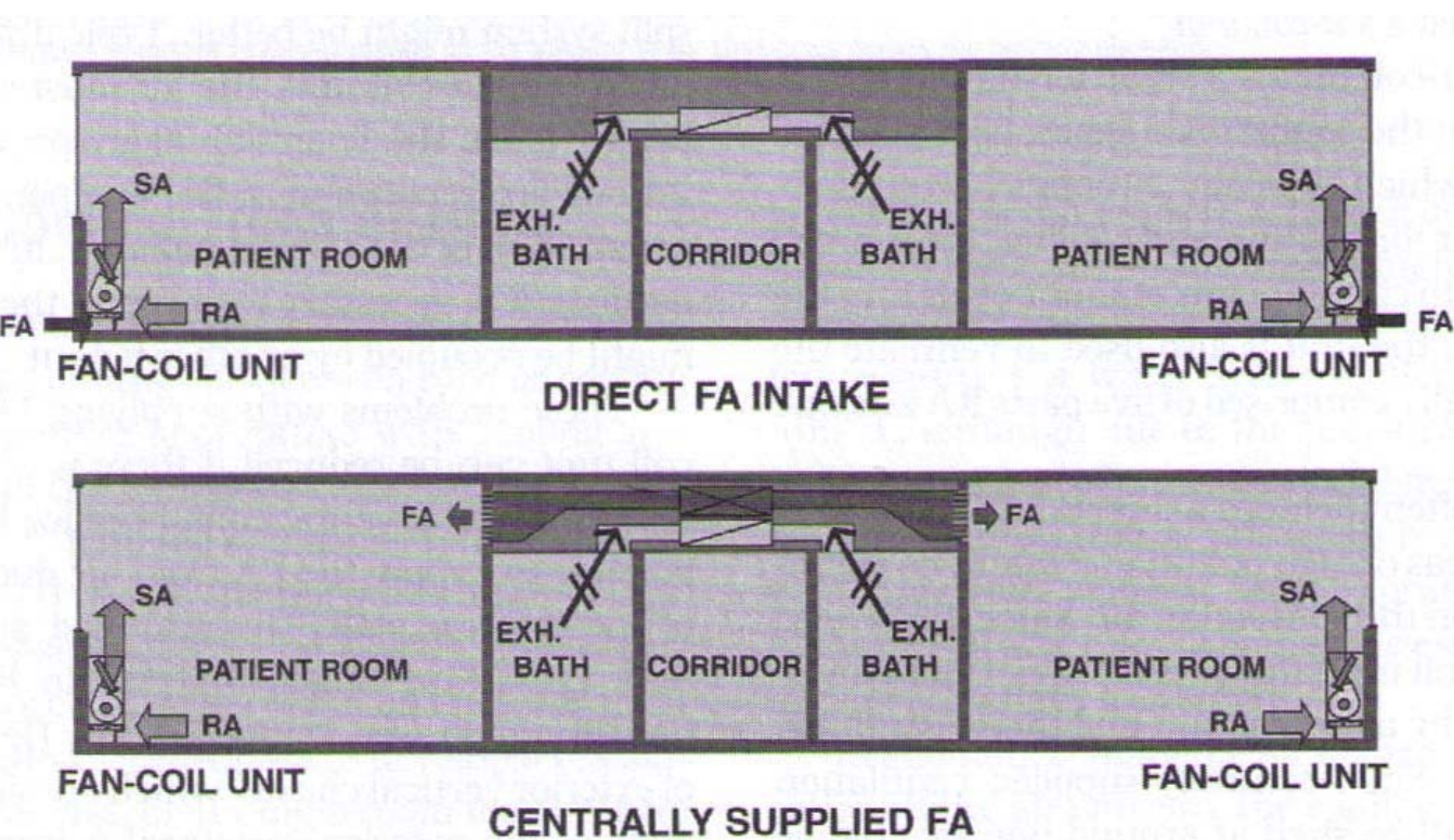
| Ventilation Systems: 2. HYDRONIC SYSTEMS: | • Integration with Fan Coil Units • Dehumidification & Air Quality |
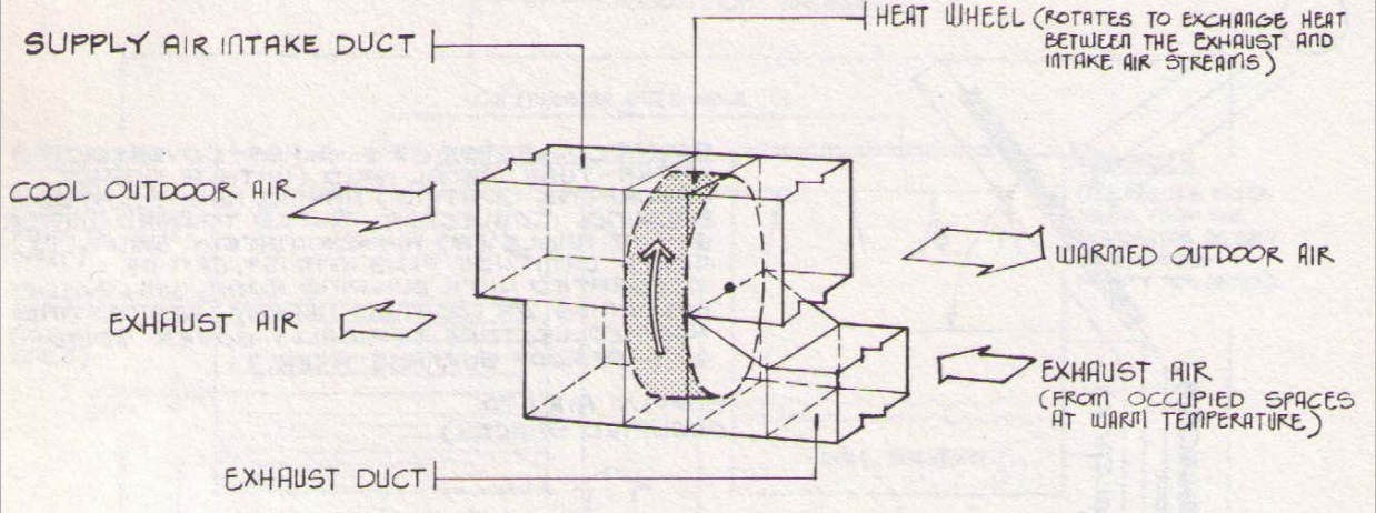
| Ventilation Systems 3. DEDICATED OUTSIDE AIR SYSTEMS (DOAS): | • Energy Recovery • Ventilation Standards: ASHRAE 62: 20 CFM/person (offices) • Dehumidification and Air Quality |
| Ventilation Systems INTEGRATED FRESH AIR/EXHAUST: Fully Ducted Systems | • Energy Recovery • Ventilation Standards: ASHRAE 62: 20 CFM/person (offices) • Dehumidification and Air Quality |
| Ventilation Systems: Integration with Ductless and Ducted Systems | |
| Ventilation Systems: DOAS Heat Recovery: (dedicated outdoor air system) HEAT WHEEL wheel has heat absorbing materials, materials absorb heat from warm environment, wheel rotates, transfers heat to colder air intake | |
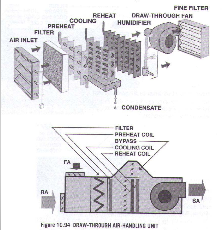
| Ducted Systems: 1. AIR HANDLING UNITS (AHU’s): | - Components - Supply, Return, Fresh Air & Exhaust; Economiser Cycle - AHU Configurations |
| Ducted Systems: 2. DUCTED HVAC SYSTEM OPTIONS: | • Multi-Zone • Variable Air Volume (VAV) • High Velocity Double Duct |
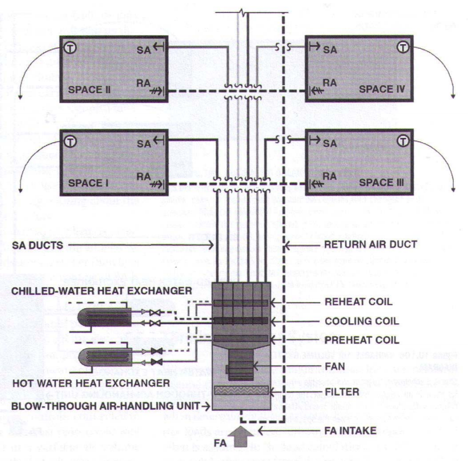
| Ducted Systems: Air-Handling Units (AHU) air inlet filer preheat cooling condensate reheat humidifier draw-through fan fine filer | |
| Ducted Systems: Roof-Top “Package” Unit (RTU) | |
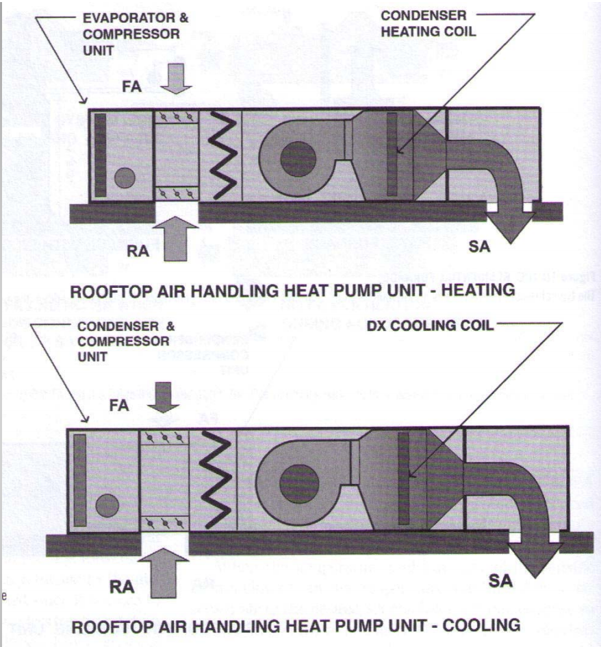
| Ducted Systems: Roof‐Top “Air‐to Air” Heat Pump Unit | |
| Ducted Systems: Multi-Zone AHU System Moderate Control, Medium Cost, Moderate Efficiency | |
| Ducted Systems: VAV System Good Control, Medium Cost, Best Efficiency | |
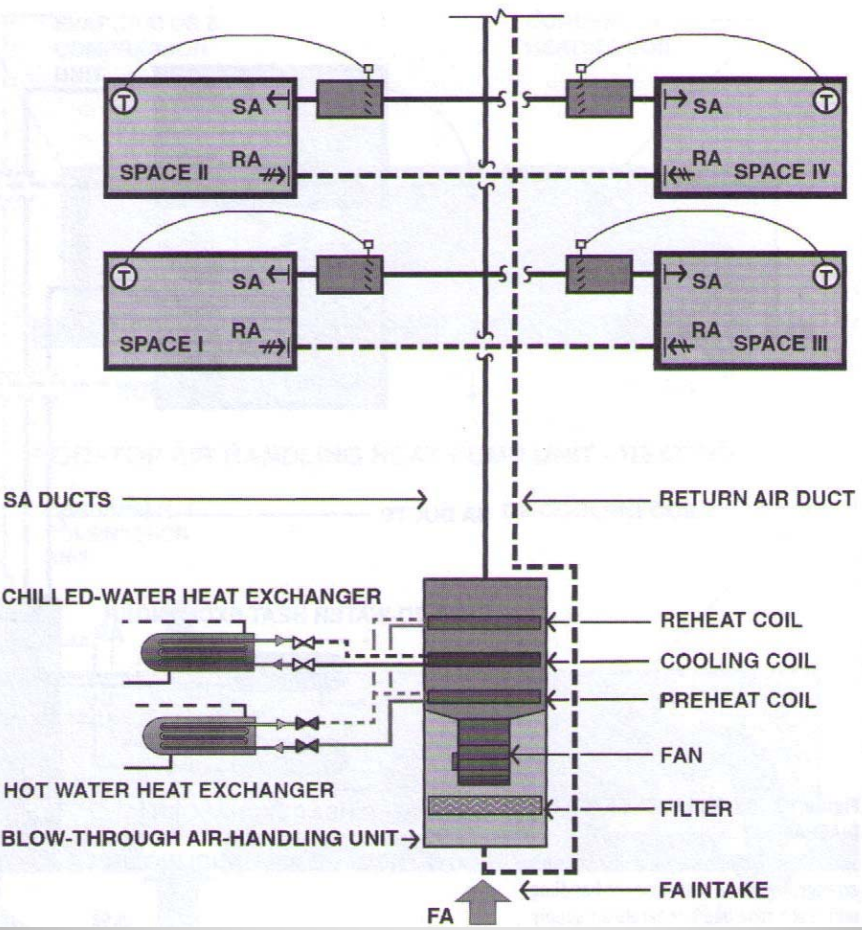
| Ducted Systems: VAV System with Re-Heat Excellent Control, High Cost, Lower Efficiency | |
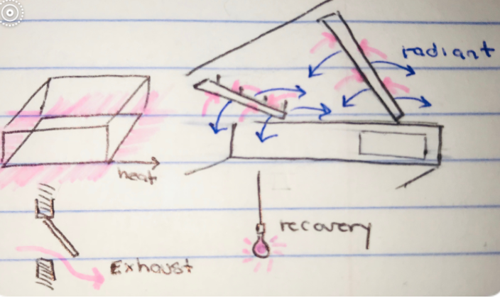
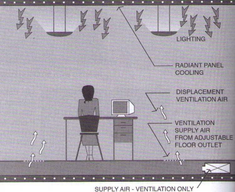
| Miscellaneous HVAC Issues | 1. PERIMETER HEAT LOSS/MRT CONTROL: • Cold Exterior Walls • Dew Point Issues at Window Systems 2. HEAT RECOVERY from EXHAUST AIR • Energy Loss due to Ventilation Requirements • Heat Wheels 3. HEAT RECOVERY from LIGHT FIXTURES • Multi-Zone • Variable Air Volume (VAV) 4. RADIANT COOLING • Chilled Beams • The Condensation Issue • Radiant Cooling and Displacement Ventilation |
| Miscellaneous HVAC Issues | |
| Approaches to Perimeter Heat Loss and MRT Control | |
| Hydronic Systems: Chilled Beams | linear active chilled beams provide air distribution in open office applications...radiant cooling |
| Displacement Ventilation /Radiant Cooling (min. Fan Energy) (good for spaces w/o high latent load) | |
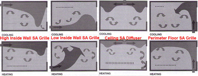
| Distribution: Ductwork TERMINAL DEVICES: | - grilles - registers - diffusers |
| Ductwork: Air Volume and Velocity | |
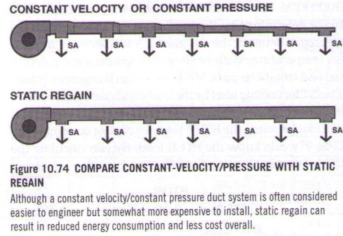
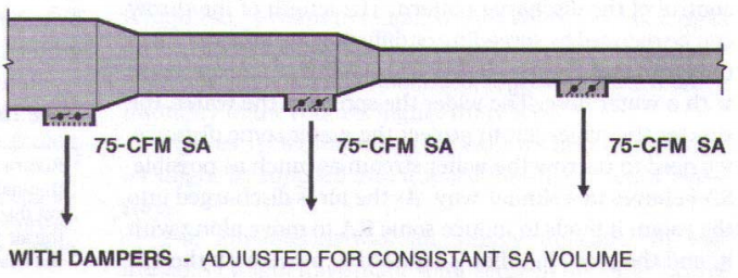
| Supply Air Balancing | |
| Duct Sizing: | DUCT CROSS SECTION AREA (A): A (duct area) = CFM (supply volume) ÷ FPM (duct velocity) A = CFM/FPM |
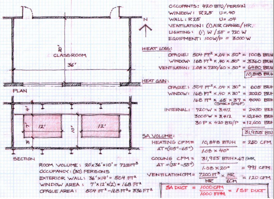
| Duct Sizing: SUPPLY VOLUME (CFM): | • Determined by WORST CASE of Heating, Cooling, or Ventilation Load. • CFM (SupPLY Vol.) = Sensible Load (BTUH) ÷ (1.08 × ∆T) • ∆T = (T (SA) - T (RA) ); ∆T≈ 20° (cooling); ∆T ≈40° - 50° (heating) • ≈ 6 air changes/hour, or roughly equal to room area in CFM. |
| Duct Sizing: DUCT VELOCITY (FPM): | - Low Pressure Ductwork: <1000 FPM - High Pressure Ductwork: 2000-3000 FPM *RULE of THUMB: 1 CFM per 1 sq. ft. room (or 1 sq.ft. duct at 1000 fpm) |
| Duct Sizing Calculation | |
| SA VOLUME (for last problem) | SA VOLUME: heating CFM(f^3 / min) = 10,848 BTUH (HL) ÷ (1.08 x 40°) = 250 CFM cooling CFM(f^3 / min) = (31,955 BTUH (HL) x .67 SHR) ÷ (1.08 x 20°) = 991 CFM ventilation CFM = (7200 ft^3 ÷ HR) x (HR ÷ 60M) = 120 CFM SA DUCT = 1000CFM ÷ 1000 FPM = 1 sf duct |
| Fully Ducted Systems: Rule of Thumb Design | 1. AIR VOLUME ESTIMATING: 1 CFM/1 SF 2. SUPPLY & RETURN MAIN DUCT and RISER SIZING: 1 ft^2 duct/1000 CFM (≈1000 FPM velocity, or 1SF cross section for ea. 1000 CFM) 3. AIR HANDLER SIZE ESTIMATION: roughly 2-3 SF/1000 CFM 4. BRANCH DUCTWORK: 2 SF duct per 1000 SF of room area |
| TERMINAL DEVICES: Grilles, Registers, and Diffusers (ceiling diffuser + large glazed exp., perimeter HL cannot be adequately controlled....consider split system) | |
| HVAC Control Zoning: Principles | 1. USE / OCCUPANCY INCONGRUITY: Provide different zones for distinct user groups 2. USE / OCCUPANCY SCHEDULE INCONGRUITY: Provide separate zones for uses which are used at different times of the day/ event related 3. EXTERIOR ORIENTATION: Provide separate zones for spaces with different heat gain loads due to glazing or solar orientation. 4. PERIMETER / INTERIOR LOCATION: Provide different zones for perimeter spaces with envelope gains and losses, + interior spaces with lighting/equipment loads 5. EQUIPMENT LIMITATIONS: ducts (space req.) AHUs (space req.) |
| Zoning: Perimeter/Interior; Solar Exposure; Use | interior zones generally have constant loads, i.e. year round cooling. on cool days, systems can be designed to use outdoor air for "free" cooling |
| HVAC Controls... 1. COMFORT CONDITIONS: 2. SEQUENCE of OPERATIONS: 3. OCCUPANT VARIABLES: | 1. COMFORT CONDITIONS: DBT, WBT (RH), MRT, FPM, and AQ 2. SEQUENCE of OPERATIONS: - HVAC systems have complex operating software -Fans, pumps, boilers, condensers, motorized dampers, motorized valves, reheat coils, etc. - DDCS: Direct digital control systems: proprietary software -Energy Conservation: Nighttime setbacks; Un-occupied mode; CO2 monitors. 3. OCCUPANT VARIABLES: Occupant metabolism is not constant! |
| Systems Planning Considerations | 1. LOCATION OF PRIMARY PLANT: 2. DISTRIBUTION MEDIUM: 3. LOCATION of SECONDARY PLANT (AHU’s): |
| Systems Planning Considerations DISTRIBUTION MEDIUM: | - HYDRONIC DISTRIBUTION: LOW distribution energy (pumps); SMALLER size elements (pipes); ability to distribute over long distances in plan and section - AIR DISTRIBUTION: HIGH distribution energy (fans); LARGER size elements (ducts); no water hazards in program spaces - REFRIGERANT DISTRIBUTION: LOW distribution energy; very SMALL elements (refrigerant tubing); limited distance (125 ft. or so) |
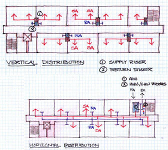
| Systems and Building Organization 1. PLAN CONSIDERATIONS: 2. SECTION CONSIDERATIONS: 3. HORIZONTAL vs. VERTICAL ORGANIZATION: | 1. PLAN CONSIDERATIONS: - ACCESS FRESH AIR (FA) & EXHAUST (EX) - SHAFTS & CHASES -> VERT. DUCT + PIPE - STRUCTURAL COORD.: DECK HOLES 2. SECTION CONSIDERATIONS: - CEILING CAVITY DEPTH (DUCTS) - STRCUTURAL COORD: (DUCTS & BEEMS) 3. HORIZONTAL vs. VERTICAL ORGANIZATION: - HORIZ. ORG.= MORE SECTION HEIGHT (D) - VERT. ORG.= MORE PLAN AREA (DUCTS) |
| Ducted Systems: Horizontal Distribution/Vertical (Riser) Distribution | |
| Conventional HVAC Systems: CHARACTERISTICS: (NEXT FLASH CARD SHORTENED VERSION...) | Dependent on hydrocarbon fuels for heating • Dependent on off-site electricity and mechanical refrigeration cycle for cooling • Do not do balance simultaneous heating and cooling loads effectively • Designed for steady state (DBT) operations • Sized for worst case heating and cooling loads (typically operating at partial capacity, often at fractional capacity) • Designed and sized for DBT rapid response rather than sustained cycles. • Utilize waste heat produced by their operations ineffectively or not at all • Reject waste heat into the public domain • Do not store energy in any form on diurnal or seasonal/annual cycle • Have limited scalability of heating and cooling capacities • Encourage thoughtless or oblivious use by occupants through automatic operation • Do not respond effectively to metabolic cycles of users • Designed for ease of operations and maintenance rather than energy efficiency • Accepts ASHRAE 90.1 as the standard for performance |
| Conventional HVAC Systems: CHARACTERISTICS: | - HYDROCARBON FUELS - MECHANICAL REFRIGERATION CYCLE - SIMULTANEOUS HEATING/COOLING - DBT -WORST CASE HEATING/COOLING - DBT RAPID RESPONSE - WASTE HEAT - STORING ENERGY? - LIMITED SCALABILITY - AUTOMATIC OPERATION - INEFFIC. RESP. TO METABOLIC CYCLE - EASY OPERAT. AND MAINTENANCE OVER EFFICIENCY - ACCEPTS ASHRAE 90.01 |
| REPEAT !!! Conventional HVAC System Energy Efficiency Coefficient of Performance (COP): | The ratio of heat produced in BTU to the energy required to drive the refrigeration (or heating) process in BTU. |
| REPEAT !!! Conventional HVAC System Energy Efficiency Energy Efficiency ratio (EER): | The ratio of heat produced in BTU to the input energy in watts. (EER is 3.413 x COP) |
| Reduced Energy Demand: 1. Envelope Optimization: 2. Behavior Patterns and Cultural Expectations: | 1. ENVELOPE OPTIMIZATION: - High Perform. Env: Conductive Gains + Losses - High Perform. Env: Radiant Gains & Losses - Maximizing Passive Strategies -Passive House Design Principles 2. BEHAVIOR PATTERNS + CULTURAL EXP. - Comfort Set Points - Passive Alternatives - Clothing and Activity |
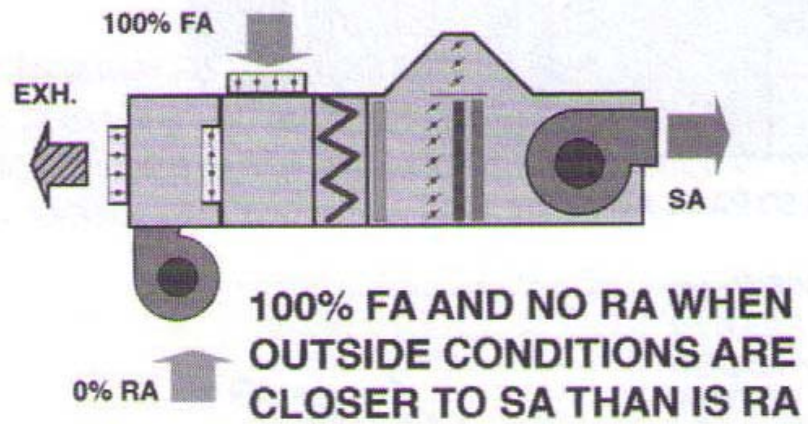
| (Optim. of Conventional HVAC Systems) ECONOMISER CYCLE: | Utilizing outside air to condition interior space during “swing” season |
| (Optim. of Conventional HVAC Systems) HIGH EFFICIENCY SYSTEMS: | - Exceeding ASHRAE 90.1 Baseline - High COP Systems - Ground Source Heat Pumps |
| (Optim. of Conventional HVAC Systems) SEQUENCE OF OPERATIONS: | Response to a range of conditions |
| (Optim. of Conventional HVAC Systems) PARTIAL LOAD EFFICIENCY: | - Incremental Equipment Units - Variable Speed Drives |
| (Optim. of Conventional HVAC Systems) CONTROL SYSTEMS: | - Unitary Controls - DDCS/BMS System |
| (Optim. of Conventional HVAC Systems) COMMISSIONING: | - LEED 2009 EA Prerequisite : Basic Commissioning - LEED 2009 EA Credit 3: Enhanced Commissioning |
| Economiser Cycle for AHU’s: Use 100% Outside Air Whenever Possible | |
| Best HVAC Practice | 1. Reduced Fan Energy 2. Reduced Ventilation Loads 3. Simultaneous Heating & Cooling 4. Utilization of Waste Heat 5. Thermal Storage (thermal batteries) |
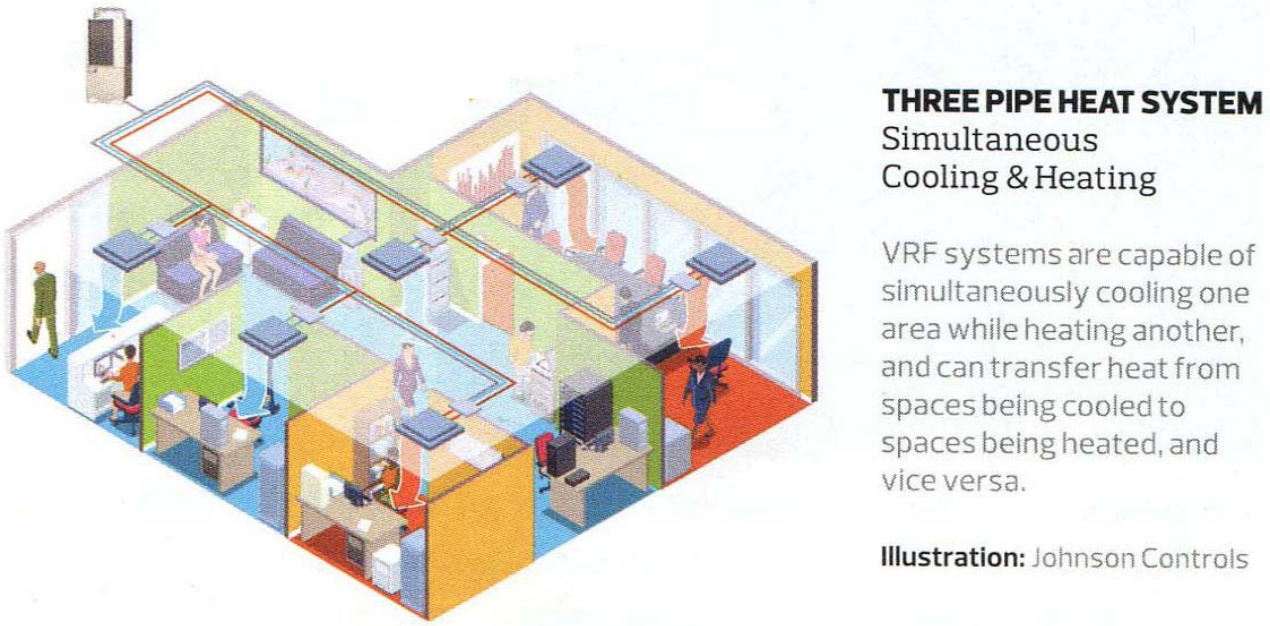
| Best HVAC Practice (MORE DETAIL) | 1. Reduced Fan Energy: • Hydronic & Chilled Beam Systems • Displacement Ventilation 2. Reduced Ventilation Loads: • Exhaust Heat Recovery (DOAS/ Heat Wheels) • Demand Control Ventilation (CO 2 Monitoring) 3. Simultaneous Heating & Cooling: • Heat Pumps • Variable Refrigerant (VRF) Systems 4. Utilization of Waste Heat: • Cogeneration • Heat Recovery Chillers • Condensing Boilers 5. Thermal Storage (thermal batteries): • Chilled Water Storage • Ice Storage |
| Reduced Ventilation Loads | 1. Sensible and Latent Ventilation Loads: Significant Energy Demand HL (ventilation): BTUH (sens) = 1.08 × CFM × ∆T (T(I) - T(O)) 2. Demand Control Ventilation: |
| Simultaneous Heating & Cooling: Variable Refrigerant Flow (VRF) Systems | |
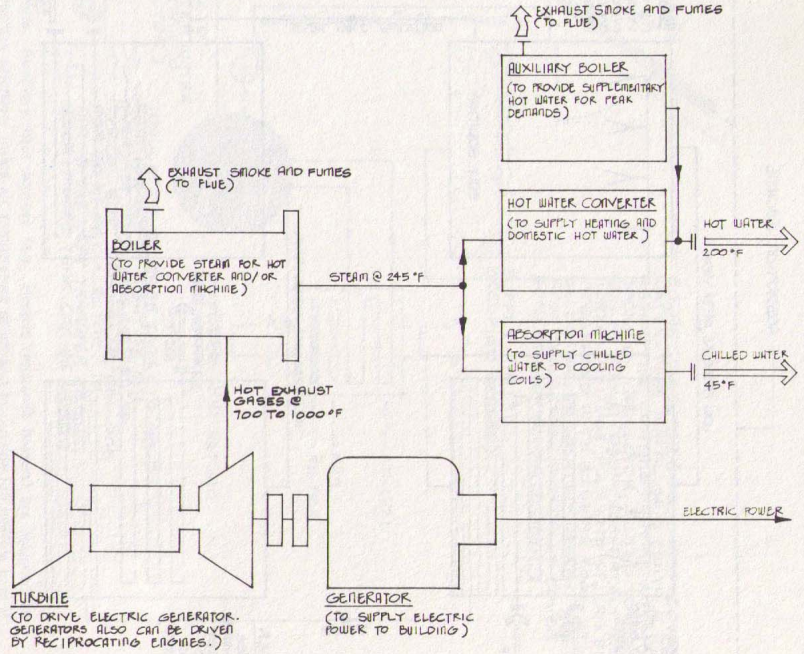
| Utilization of Waste Heat: Cogeneration Plant or Micro-turbines TOTAL ENERGY SYSTEM: | |
| Thermal Storage: Diurnal and Seasonal Cycles | |
| ICE THERMAL STORAGE | AC that uses ice for thermal energy storage |
| ENERGY STORAGE: COMPRESSED AIR | WIND TURBINES?? |
| HVAC Systems: Frontiers | - Utilization of Waste Heat: REJECTED HEAT, STACK LOSSES (COND. BOIL. FURN) -Balancing of Simultaneous Heating & Cooling Loads: N / S EXPOSURE, ZONES - Thermal Storage: DIRUNAL/ANNUAL CYC . -Utilization of “Free “ Energy: SOLAR/WIND |
| "FREE ENERGY" On-site Electrical Power Generation: | - Solar: PV Arrays - Wind: Wind Turbines |
| "FREE ENERGY" Solar Heating: | • Active Solar Heating • Passive Solar Heating |
| "FREE ENERGY" Wind Power: | • Small Scale Windmills • Utility Scale Windmills |
| "FREE ENERGY" Evaporative Cooling: | - Evaporative Roofs - Evaporative Courtyards |
| Evaporative Roof Cooling | spraying rood with water intermittently to reduce SA |
| Reduction of HVAC Loads | |
| PASSIVE HOUSE ENVELOPE AND THERMAL COMFORT PRINCIPLES: | 1. CONTINUOUS INSULATION 2. THERMAL BRIDGE FREE CONSTRUCTION 3. COMPACT BUILDING SHAPE 4. AIRTIGHTNESS 5. BALANCED VENTILATION W/ HEAT RECONVERY W/ MINIMAL SPACE CONDITIONING SYSTEM 6. OPTIMAL SOLAR OREINTATION AND SHADING 7. ENERGY EFFICIENT APPLIANCES AND LIGHTING 8. USER FRIENDLINESS |
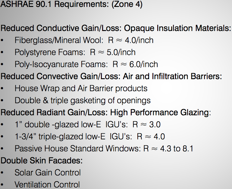
| Performance Evaluation ASHRAE 90.1 2016 ZONE 4 minimums: (non-residential) | • ROOFS: R-30 • OPAQUE WALLS (STEEL FRAMED): R-13 + R-7.5 c.i. (continuous insulation) • FLOORS: R-30 • OPAQUE DOORS: U-.37/R-2.7 • VERT. GLAZING (WINDOWS): max. U-.36/R-2.78 (max. 40% wall area) • SKYLIGHTS: U-.5/R-2.0 |
| Performance Evaluation INFILTRATION RATE | • 1.5 AC/hr. (1.5 x conditioned volume of building/hr.) |
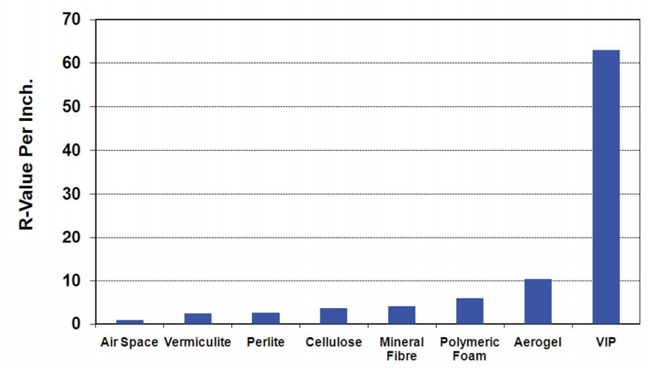
| THERMAL PERFORMANCE Comparison of Insulation Materials Resistivity | |
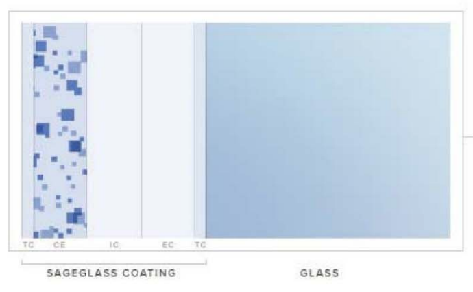
| Radiant Gains: Dynamic Glazing | TC, CE, IC, EC, TC, GLASS: DARKENED STATE ALLOWS GLASS TO ABSORB AND RERADIATE AWAY SUN'S UNWANTED HEAT AND GLARE |
| U VALUE PERFORMANCE COMPARISON HEAT MIRROR IGU | I THINK ARGON IS BETTER THAN KRYPTON...IDK |
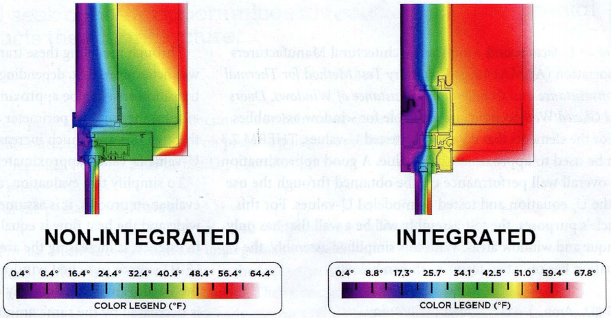
| Thermal Bridging Analysis: Conductive Envelope Gaps | LEFT: NO THERMAL BREAK, NON INTEGR. RIGHT: W/ THERMAL CREAK, INTEGRATED |
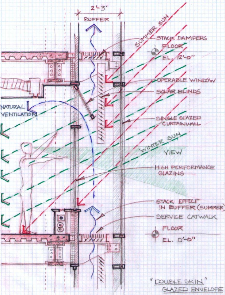
| DOUBLE SKIN FACADE: | A constructed buffer zone for transparent (glazed) facades. |
| DOUBLE SKIN FACADE: WINTER | - Buffer zone temperature mitigated by solar gain, wind protection = LESS ∆T - Permits direct solar gain to interior space |
| DOUBLE SKIN FACADE: SUMMER/SWING SEASONS | • Buffer zone temperature mitigated by stack ventilation = LESS ∆ T • shading device blocks solar gain • Natural ventilation to “free” cool building mass during lower night-time temperatures • Improved SHGC with additional layer of glass |
| Double Skin Façade: Concepts | |
| High Performance Envelope | • Minimized Envelope (low surface to volume ratio (SVR)) • Optimized Massing • Conduction: High Performance Insulation • Convection: High Performance Infiltration Barriers • Radiation: High Performance Glazing |
| Predicting Performance | 1. BUILDING MODELS: 2. SIMULATION: 3. RESPONSIBILITY: - NOW: design code minimum compliance - Green Certifications: NOT REQUIRED - Future: required perform. certifications |
| BUILDING MODELS | • 3-dimensional digital scale models of buildings • Location and orientation of building model in solar space, climate zones • Attributes of building components such as R value, SHGF |
| SIMULATION: | • Intelligent modeling allows manipulation of building attributes • Testing of various systems options in the model • Development of energy quantities, energy costs, carbon footprint • Ability to optimize performance prior to construction and fit-out |
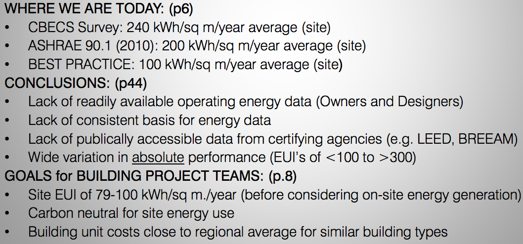
| HOW GREEN ARE WE TODAY? |
Want to create your own Flashcards for free with GoConqr? Learn more.