4956427
Description
Flashcards by John Dedios, updated more than 1 year ago
|
|
Created by John Dedios
almost 10 years ago
|
|
| Question | Answer |
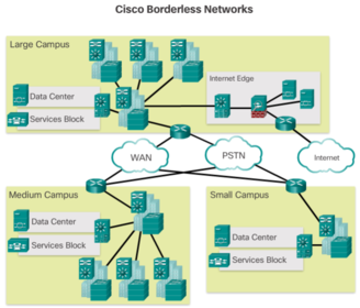
| The Cisco Borderless Network is a network architecture combining innovation and design that allows organizations to support a borderless network that can connect anyone, anywhere, anytime, on any device - securely, reliably, and seamlessly. This architecture is designed to address IT and business challenges, such as supporting the converged network and changing work patterns. | |
| Borderless switched network design guidelines are built upon the following principles: * Hierarchical - Facilitates understanding the role of each device at every tier, simplifies deployment, operation, and management, and reduces fault domains at every tier | * Modularity - Allows seamless network expansion and integrated service enablement on an on-demand basis * Resiliency - Satisfies user expectations for keeping the network always on * Flexibility - Allows intelligent traffic load sharing by using all network resources |
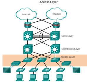
| The distribution layer interfaces between the access layer and the core layer to provide many important functions, including: 1. Aggregating large-scale wiring closet networks 2. Aggregating Layer 2 broadcast domains and Layer 3 routing boundaries | 3. Providing intelligent switching, routing, and network access policy functions to access the rest of the network 4. Providing high availability through redundant distribution layer switches to the end-user and equal cost paths to the core 5. Providing differentiated services to various classes of service applications at the edge of the network |
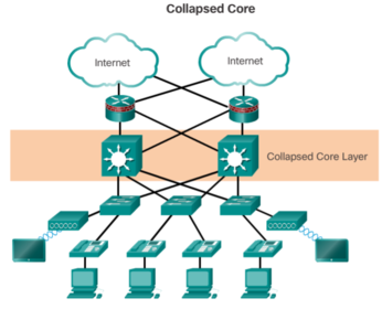
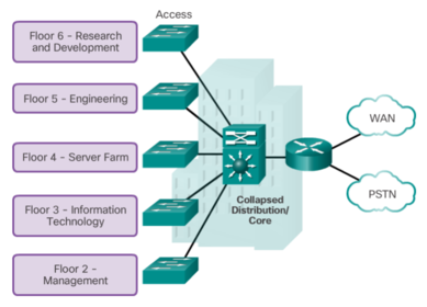
| The primary purpose of the core layer is to provide fault isolation and high-speed backbone connectivity. To build a simplified, scalable, cost-effective, and efficient physical cable layout design, the recommendation is to build an extended-star physical network topology from a centralized building location to all other buildings on the same campus. A two-tier campus network design example for an enterprise campus where the distribution and core layers are collapsed into a single layer. | |
| A switched LAN allows more flexibility, traffic management, and additional features, such as: * Quality of service | * Additional security * Support for wireless networking and connectivity * Support for new technologies, such as IP telephony and mobility services |
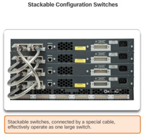
| Stackable Configuration Switches Cisco StackWise technology allows the interconnection of up to nine switches. Switches can be stacked one on top of the other with cables connecting the switches in a daisy chain fashion. Many Cisco stackable switches also support StackPower technology, which enables power sharing among stack members. | |
| The following steps describe the process of building the MAC address table: 1. The switch receives a frame from PC 1 on Port 1 2. The switch examines the source MAC address and compares it to MAC address table. * If the address is not in the MAC address table, it associates the source MAC address of PC 1 with the ingress port (Port 1) in the MAC address table * If the MAC address table already has an entry for that source address, it resets the "aging timer". An entry for a MAC address is typically kept for five minutes. 3. After the switch has recorded the source address information, the switch examines the destination MAC address. | * If the destination address is not in the MAC table or if it’s a broadcast MAC address, as indicated by all Fs, the switch floods the frame to all ports, except the ingress port 4. The destination device (PC 3) replies to the frame with a unicast frame addressed to PC 1 5. The switch enters the source MAC address of PC 3 and the port number of the ingress port into the address table. The destination address of the frame and its associated egress port is found in the MAC address table 6. The switch can now forward frames between these source and destination devices without flooding, because it has entries in the address table that identify the associated ports |
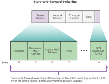
| Automatic Buffering For example, handling an incoming frame traveling into a 100 Mb/s Ethernet port that must be sent out a 1 Gb/s interface would require using the store-and-forward method. With any mismatch in speeds between the ingress and egress ports, the switch stores the entire frame in a buffer, computes the FCS check, forwards it to the egress port buffer and then sends it. A store-and-forward switch drops frames that do not pass the FCS check, therefore does not forward invalid frames. By contrast, a cut-through switch may forward invalid frames because no FCS check is performed. | |
| El switching libre de fragmentos es una forma modificada del switching por método de corte en la cual el switch espera a que pase la ventana de colisión (64 bytes) antes de reenviar la trama. Esto significa que cada trama se registra en el campo de datos para asegurarse de que no se produzca la fragmentación. El modo libre de fragmentos proporciona una mejor verificación de errores que el de corte, con prácticamente ningún aumento de latencia. | Con la ventaja de la velocidad de latencia más baja que la del switching por método de corte, este modo resulta más adecuado para las aplicaciones muy exigentes de tecnología informática de alto rendimiento (HPC) que requieren latencias de proceso a proceso de 10 microsegundos o menos |
| It is possible, however, to use a switch device, operating the OSI data link layer, to divide a network into segments and reduce the number of devices that compete for bandwidth. When a switch is used, each port represents a new segment. Each new segment is a new collision domain. | More bandwidth is available to the devices on the segment, and collisions in one collision domain do not interfere with the other segments. This is also known as microsegmentation. |
| After a Cisco switch is powered on, it goes through the following boot sequence: 1. First, the switch loads a power-on self-test (POST) program stored in ROM. POST checks the CPU subsystem. It tests the CPU, DRAM, and the portion of the flash device that makes up the flash file system. 2. Next, the switch loads the boot loader software. The boot loader is a small program stored in ROM and is run immediately after POST successfully completes. | 3. The boot loader performs low-level CPU initialization. It initializes the CPU registers, which control where physical memory is mapped, the quantity of memory, and its speed. 4. The boot loader initializes the flash file system on the system board. 5. Finally, the boot loader locates and loads a default IOS operating system software image into memory and hands control of the switch over to the IOS. |
| The boot loader finds the Cisco IOS image on the switch as follows: the switch attempts to automatically boot by using information in the BOOT environment variable. If this variable is not set, the switch attempts to load and execute the first executable file it can by performing a recursive, depth-first search throughout the flash file system | In a depth-first search of a directory, each encountered subdirectory is completely searched before continuing the search in the original directory. On Catalyst 2960 Series switches, the image file is normally contained in a directory that has the same name as the image file (excluding the .bin file extension). The IOS operating system then initializes the interfaces using the Cisco IOS commands found in the configuration file, startup-config, which is stored in NVRAM. |
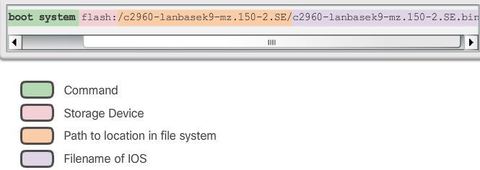
| In the figure, the BOOT environment variable is set using the "boot system" global configuration mode command. Notice that the IOS is located in a distinct folder and the folder path is specified. Use the "show bootvar" command ("show boot" in older IOS versions) to see what the current IOS boot file is set to. | |
| Recovering From a System Crash The boot loader can be accessed through a console connection following these steps: Step 1. Connect a PC by console cable to the switch console port. Configure terminal emulation software to connect to the switch. Step 2. Unplug the switch power cord. | Step 3. Reconnect the power cord to the switch and, within 15 seconds, press and hold down the Mode button while the System LED is still flashing green. Step 4. Continue pressing the Mode button until the System LED turns briefly amber and then solid green; then release the Mode button. Step 5. The boot loader switch: prompt appears in the terminal emulation software on the PC. |
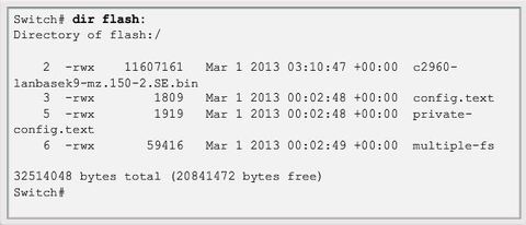
| The boot loader command line supports commands to format the flash file system, reinstall the operating system software, and recover from a lost or forgotten password. Note: Notice that in this example, the IOS is located in the root of the flash folder. | |
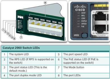
| The Mode button is used to toggle through port status, port duplex, port speed, and PoE (if supported) status of the port LEDs. | |
| * System LED - Shows whether the system is receiving power and is functioning properly. If the LED is off, it means the system is not powered on. If the LED is green, the system is operating normally. If the LED is amber, the system is receiving power but is not functioning properly. | * Redundant Power System (RPS) LED - If the LED is off, the RPS is off or not properly connected. If the LED is green, the RPS is connected and ready to provide back-up power The LED is blinking green, the RPS is connected but is unavailable because it is providing power to another device. If the LED is amber, the RPS is in standby mode or in a fault condition. If the LED is blinking amber, the internal power supply in the switch has failed, and the RPS is providing power. |
| * Port Status LED - If the LED is off, there is no link, or the port was administratively shut down. If the LED is green, a link is present. If the LED is blinking green, there is activity and the port is sending or receiving data. | If the LED is alternating green-amber, there is a link fault. If the LED is amber, the port is blocked to ensure a loop does not exist in the forwarding domain and is not forwarding data (typically, ports will remain in this state for the first 30 seconds after being activated). If the LED is blinking amber, the port is blocked to prevent a possible loop in the forwarding domain |
| * Port Duplex LED - Indicates the port duplex mode is selected when the LED is green. When selected, port LEDs that are off are in half-duplex mode. If the port LED is green, the port is in full-duplex mode. | * Port Speed LED - Indicates the port speed mode is selected. When selected, the port LEDs will display colors with different meanings. If the LED is off, the port is operating at 10 Mb/s. If the LED is green, the port is operating at 100 Mb/s. If the LED is blinking green, the port is operating at 1000 Mb/s. |
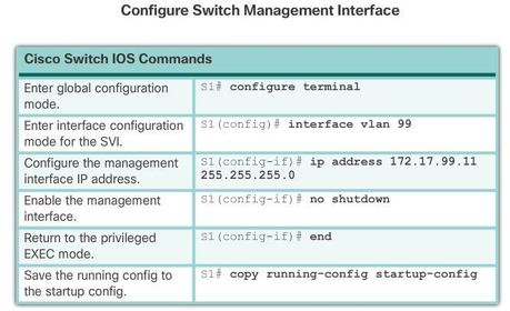
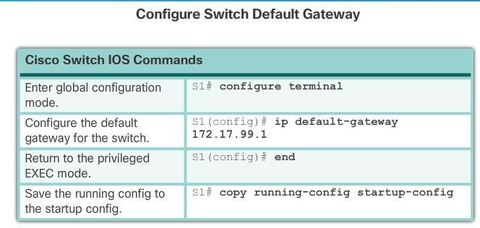
| In the switch virtual interface (SVI) on S1 should be assigned an IP address. The SVI is a virtual interface, not a physical port on the switch. SVI is a concept related to VLANs. VLANs are numbered logical groups to which physical ports can be assigned. Configurations and settings applied to a VLAN are also applied to all the ports assigned to that VLAN. | By default, the switch is configured to have the management of the switch controlled through VLAN 1. All ports are assigned to VLAN 1 by default. For security purposes, it is considered a best practice to use a VLAN other than VLAN 1 for the management VLAN. Note that these IP settings are only for remote management access to the switch; the IP settings do not allow the switch to route Layer 3 packets. |
| Configuring Basic Switch Management Access with IPv4 S1(config)# vlan vlan_id S1(config-vlan)# name vlan_name | S1(config-vlan)# exit S1(config)# interface interface_id S1(config-if)# switchport access vlan vlan_id |
| Full-duplex communication improves the performance of a switched LAN. Full-duplex communication increases effective bandwidth by allowing both ends of a connection to transmit and receive data simultaneously. This method of optimizing network performance requires micro-segmentation. | A micro-segmented LAN is created when a switch port has only one device connected and is operating at full-duplex. This results in a micro size collision domain of a single device. However, because there is only one device connected, a micro-segmented LAN is collision free. |
| Gigabit Ethernet and 10Gb NICs require full-duplex connections to operate. In full-duplex mode, the collision detection circuit on the NIC is disabled. Frames that are sent by the two connected devices cannot collide because the devices use two separate circuits in the network cable. | Standard, shared hub-based Ethernet configuration efficiency is typically rated at 50 to 60 percent of the stated bandwidth. Full-duplex offers 100 percent efficiency in both directions (transmitting and receiving). This results in a 200 percent potential use of the stated bandwidth. |
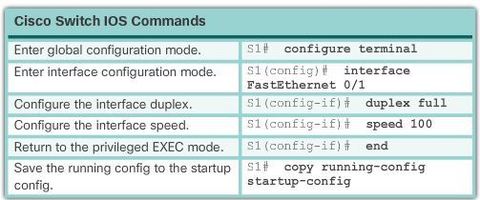
| Switch ports can be manually configured with specific duplex and speed settings. Use the duplex interface configuration mode command to manually specify the duplex mode for a switch port. Use the speed interface configuration mode command to manually specify the speed for a switch port. | |
| The default setting for both duplex and speed for switch ports on Cisco Catalyst 2960 and 3560 switches is auto. The 10/100/1000 ports operate in either half- or full-duplex mode when they are set to 10 or 100 Mb/s, but when they are set to 1000 Mb/s (1 Gb/s), they operate only in full-duplex mode. Auto-negotiation is useful when the speed and duplex settings of the device connecting to the port are unknown or may change | When troubleshooting switch port issues, the duplex and speed settings should be checked. Note: Mismatched settings for the duplex mode and speed of switch ports can cause connectivity issues. Auto-negotiation failure creates mismatched settings. All fiber optic ports, such as 100BASE-FX ports, operate only at one preset speed and are always full-duplex. |
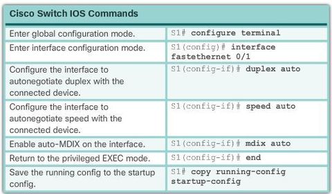
| When using auto-MDIX on an interface, the interface speed and duplex must be set to auto so that the feature operates correctly. The auto-MDIX feature is enabled by default on Catalyst 2960 and Catalyst 3560 switches, but is not available on the older Catalyst 2950 and Catalyst 3550 switches. | |
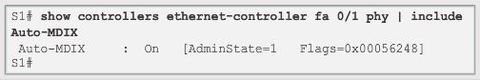
| To examine the auto-MDIX setting for a specific interface, use the: "show controllers ethernet-controller" command with the "phy" keyword. To limit the output to lines referencing auto-MDIX, use the include: "Auto-MDIX" filter | |
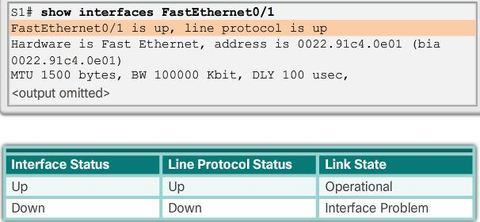
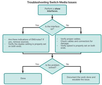
| The first parameter (FastEthernet0/1 is up) refers to the hardware layer and, essentially, reflects whether the interface is receiving the carrier detect signal from the other end. The second parameter (line protocol is up) refers to the data link layer and reflects whether the data link layer protocol keepalives are being received. | |
| Based on the output of the show interfaces command, possible problems can be fixed as follows: If the interface is up and the line protocol is down, a problem exists. There could be an encapsulation type mismatch, the interface on the other end could be error-disabled, or there could be a hardware problem. | If the line protocol and the interface are both down, a cable is not attached or some other interface problem exists. For example, in a back-to-back connection, the other end of the connection may be administratively down. If the interface is administratively down, it has been manually disabled (the shutdown command has been issued) in the active configuration. |
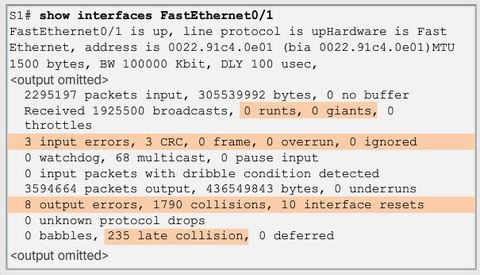
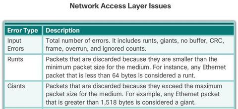
| “Input errors” is the sum of all errors in datagrams that were received on the interface being examined. * Runt Frames - Ethernet frames that are shorter than the 64-byte minimum allowed length are called runts. Malfunctioning NICs are the usual cause of excessive runt frames, but they can be caused by the same issues as excessive collisions | |
| * Giants - Ethernet frames that are longer than the maximum allowed length are called giants. Giants are caused by the same issues as those that cause runts. | |
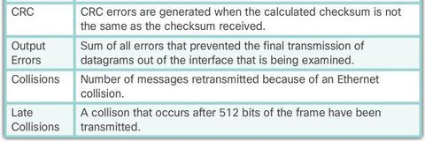
| * CRC errors - On Ethernet and serial interfaces, CRC errors usually indicate a media or cable error. Common causes include electrical interference, loose or damaged connections, or using the incorrect cabling type. If you see many CRC errors, there is too much noise on the link and you should inspect the cable for damage and length. | |
| * Collisions - Collisions in half-duplex operations are completely normal and you should not worry about them, as long as you are pleased with half-duplex operations. However, you should never see collisions in a properly designed and configured network that uses full-duplex communication. | |
| * Late collisions - A late collision refers to a collision that occurs after 512 bits of the frame have been transmitted. Excessive cable lengths are the most common cause of late collisions. Another common cause is duplex misconfiguration. For example, you could have one end of a connection configured for full-duplex and the other for half-duplex. | |
| Use the show interfaces command to check the interface status. | |
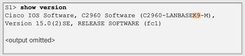
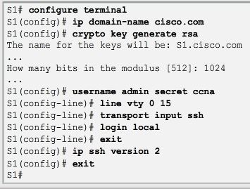
| SSH is assigned to TCP port 22. Telnet is assigned to TCP port 23. To enable SSH on a Catalyst 2960 switch, the switch must be using a version of the IOS software including cryptographic (encrypted) features and capabilities. If IOS filename includes the combination “k9” supports cryptographic (encrypted) features and capabilities. | |
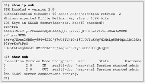
| Use the show ip ssh command to verify that the switch supports SSH. If the switch is not running an IOS that supports cryptographic features, this command is unrecognized. Note: To delete the RSA key pair, use the "crypto key zeroize rsa" global configuration mode command. After the RSA key pair is deleted, the SSH server is automatically disabled. | |
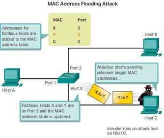
| An attacker at host C can send frames with fake, randomly-generated source and destination MAC addresses to the switch. The switch updates the MAC address table with the information in the fake frames. When the MAC address table is full of fake MAC addresses, the switch enters into what is known as fail-open mode. In this mode, the switch broadcasts all frames to all machines on the network. As a result, the attacker can see all of the frames. | |
| In DHCP starvation attacks, an attacker floods the DHCP server with DHCP requests to use up all the available IP addresses that the DHCP server can issue. After these IP addresses are issued, the server cannot issue any more addresses, and this situation produces a denial-of-service (DoS) attack as new clients cannot obtain network access DHCP starvation is often used before a DHCP spoofing attack to deny service to the legitimate DHCP server, making it easier to introduce a fake DHCP server into the network. | In DHCP spoofing attacks, an attacker configures a fake DHCP server on the network to issue IP addresses to clients. The normal reason for this attack is to force the clients to use false Domain Name System (DNS) or Windows Internet Naming Service (WINS) servers and to make the clients use the attacker, or a machine under the control of the attacker, as their default gateway. To mitigate DHCP attacks, use the DHCP snooping and port security features on the Cisco Catalyst switches. |
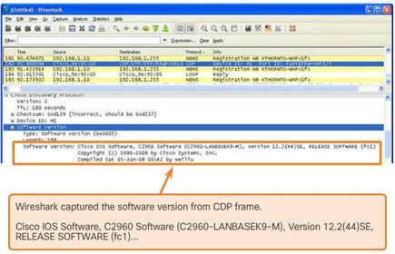
| By default, most Cisco routers and switches have CDP-enabled on all ports. CDP information is sent in periodic, unencrypted broadcasts. This information is updated locally in the CDP database of each device. Because CDP is a Layer 2 protocol, CDP messages are not propagated by routers. CDP contains information about the device, such as the IP address, IOS software version, platform, capabilities, and the native VLAN | |
| Disable Unused Ports For example, if a Catalyst 2960 switch has 24 ports and there are three Fast Ethernet connections in use, it is good practice to disable the 21 unused ports. | Navigate to each unused port and issue the Cisco IOS shutdown command Switch(config)# interface range "type module/first-number – last-number" |
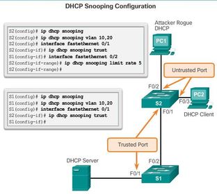
| DHCP snooping is a Cisco Catalyst feature that determines which switch ports can respond to DHCP requests. Ports are identified as trusted and untrusted. Trusted ports can source all DHCP messages, including DHCP offer and DHCP acknowledgement packets; untrusted ports can source requests only | Trusted ports host a DHCP server or can be an uplink toward the DHCP server. If a rogue device on an untrusted port attempts to send a DHCP offer packet into the network, the port is shut down. This feature can be coupled with DHCP options in which switch information, such as the port ID of the DHCP request, can be inserted into the DHCP request packet. |
| A DHCP binding table is built for untrusted ports. Each entry contains a client MAC address, IP address, lease time, binding type, VLAN number, and port ID recorded as clients make DHCP requests | |
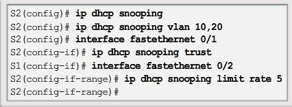
| Step 1. Enable DHCP snooping using the ip dhcp snooping global configuration mode command. Step 2. Enable DHCP snooping for specific VLANs using the ip dhcp snooping vlan number command. Step 3. Define ports as trusted at the interface level by defining the trusted ports using the ip dhcp snooping trust command. Step 4. (Optional) Limit the rate at which an attacker can continually send bogus DHCP requests through untrusted ports to the DHCP server using the ip dhcp snooping limit rate rate command. | |
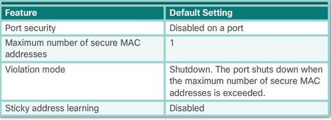
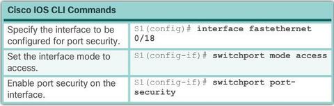
| Port security limits the number of valid MAC addresses allowed on a port. * Static secure MAC addresses - MAC addresses that are manually configured on a port by using the "switchport port-security mac-address (mac-address)" interface configuration mode command. MAC addresses configured in this way are stored in the address table and are added to the running configuration on the switch. | * Dynamic secure MAC addresses - MAC addresses that are dynamically learned and stored only in the address table. MAC addresses configured in this way are removed when the switch restarts. * Sticky secure MAC addresses - MAC addresses that can be dynamically learned or manually configured, then stored in the address table and added to the running configuration |
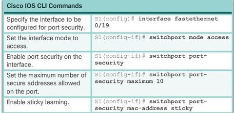
| To configure an interface to convert dynamically learned MAC addresses to sticky secure MAC addresses and add them to the running configuration, you must enable sticky learning. Sticky learning is enabled on an interface by using the "switchport port-security mac-address sticky" interface configuration mode command. | Sticky secure MAC addresses can also be manually defined with: "switchport port-security mac-address sticky (mac-address)" If sticky learning is disabled by using the no switchport port-security mac-address sticky interface configuration mode command, the sticky secure MAC addresses remain part of the address table, but are removed from the running configuration. |
| Sticky secure * Learned dynamically, converted to sticky secure MAC addresses stored in the running-config. * Removed from the running-config if port security is disabled. * Lost when the switch reboots (power cycled). | * Saving sticky secure MAC addresses in the startup-config makes them permanent and the switch retains them after a reboot. * Disabling sticky learning converts sticky MAC addresses to dynamic secure addresses and removes them from the running-config. |
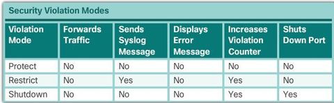
| To change the violation mode on a switch port, use the: "switchport port-security violation {protect | restrict | shutdown}" interface configuration mode command. Shutdown - In this (default) violation mode, a port security violation causes the interface to immediately become error-disabled and turns off the port LED. It increments the violation counter. When a secure port is in the error-disabled state, it can be brought out of this state by entering the shutdown and no shutdown interface configuration mode commands. | |
| As stated earlier, the maximum number of secure MAC addresses can be manually configured. In this example, the Cisco IOS command syntax is used to set the maximum number of MAC addresses to 10 for port 0/19. The violation mode is set to shutdown, by default. | |
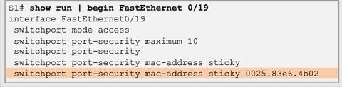
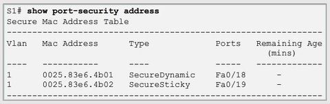
| Sticky MAC addresses are added to the MAC address table and to the running configuration. | |
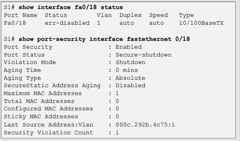
| When a port is error disabled, it is effectively shut down and no traffic is sent or received on that port Note: The port protocol and link status is changed to down. The port LED will turn off. The "show interfaces" command identifies the port status as "err-disabled" The output of the "show port-security interface" command now shows the port status as secure-shutdown. | |
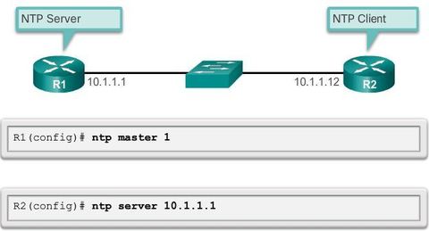
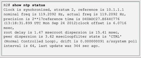
| NTP can get the correct time from an internal or external time source including the following: * Local master clock * Master clock on the Internet * GPS or atomic clock Figure: Router R2 is configured as an NTP client, while router R1 serves as an authoritative NTP server. | |
| To configure a device as having an NTP master clock to which peers can synchronize themselves, use the ntp master [stratum] command in global configuration mode. The stratum value is a number from 1 to 15 and indicates the NTP stratum number that the system will claim. | If the system is configured as an NTP master and no stratum number is specified, it will default to stratum 8. If the NTP master cannot reach any clock with a lower stratum number, the system will claim to be synchronized at the configured stratum number, and other systems will be willing to synchronize to it using NTP. |
Want to create your own Flashcards for free with GoConqr? Learn more.