5150668
Description
Flashcards by John Dedios, updated more than 1 year ago
|
|
Created by John Dedios
almost 10 years ago
|
|
| Question | Answer |
| The RIP routing protocol was updated to accommodate growth in the network environment, into RIPv2. However, the newer version of RIP still does not scale to the larger network implementations of today. To address the needs of larger networks, two advanced routing protocols were developed: Open Shortest Path First (OSPF) and Intermediate System-to-Intermediate System (IS-IS). Cisco developed the Interior Gateway Routing Protocol (IGRP) and Enhanced IGRP (EIGRP), which also scales well in larger network implementations. The Border Gateway Protocol (BGP) is now used between Internet service providers (ISPs). BGP is also used between ISPs and their larger private clients to exchange routing information. | |
| A routing protocol is a set of processes, algorithms, and messages that are used to exchange routing information and populate the routing table with the routing protocol's choice of best paths. The purpose of dynamic routing protocols includes: * Discovery of remote networks * Maintaining up-to-date routing information * Choosing the best path to destination networks * Ability to find a new best path if the current path is no longer available | |
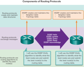
| The main components of dynamic routing protocols include: 1. Data structures - Routing protocols typically use tables or databases for its operations. This information is kept in RAM. EIGRP - DUAL | 2. Routing protocol messages - Routing protocols use various types of messages to discover neighboring routers, exchange routing information, and other tasks to learn and maintain accurate information about the network. 3. Algorithm - An algorithm is a finite list of steps used to accomplish a task. Routing protocols use algorithms for facilitating routing information and for best path determination |
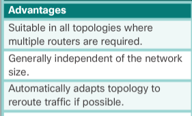
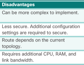
| Routing protocols determine the best path, or route, to each network. That route is then added to the routing table. A primary benefit of dynamic routing protocols is that routers exchange routing information when there is a topology change. This exchange allows routers to automatically learn about new networks and also to find alternate paths when there is a link failure to a current network. | Compared to static routing, dynamic routing protocols require less administrative overhead. However, the expense of using dynamic routing protocols is dedicating part of a router’s resources for protocol operation, including CPU time and network link bandwidth. |
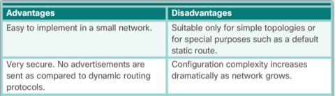
| Static routing has several primary uses, including: * Providing ease of routing table maintenance in smaller networks that are not expected to grow significantly. | * Routing to and from a stub network, which is a network with only one default route out and no knowledge of any remote networks. * Accessing a single default route (which is used to represent a path to any network that does not have a more specific match with another route in the routing table). |
| In general, the operations of a dynamic routing protocol can be described as follows: 1. The router sends and receives routing messages on its interfaces. 2. The router shares routing messages and routing information with other routers that are using the same routing protocol. | 3. Routers exchange routing information to learn about remote networks. 4. When a router detects a topology change the routing protocol can advertise this change to other routers. |
| When a router powers up, it knows nothing about the network topology. It does not even know that there are devices on the other end of its links. The only information that a router has is from its own saved configuration file stored in NVRAM. | After a router boots successfully, it applies the saved configuration. If the IP addressing is configured correctly, then the router initially discovers its own directly connected networks. Hop = 0 |
| If a routing protocol is configured, the next step is for the router to begin exchanging routing updates to learn about any remote routes. The router sends an update packet out all interfaces that are enabled on the router. The update contains the information in the routing table, which currently are all directly connected networks. | At the same time, the router also receives and processes similar updates from other connected routers. Upon receiving an update, the router checks it for new network information. Any networks that are not currently listed in the routing table are added. |
| Distance vector routing protocols typically implement a routing loop prevention technique known as split horizon. Split horizon prevents information from being sent out the same interface from which it was received. For example, R2 does not send an update containing the network 10.1.0.0 out of Serial 0/0/0, because R2 learned about network 10.1.0.0 through Serial 0/0/0. | After routers within a network have converged, the router can then use the information within the route table to determine the best path to reach a destination. Different routing protocols have different ways of calculating the best path. |
| Convergence time is the time it takes routers to share information, calculate best paths, and update their routing tables. A network is not completely operable until the network has converged; therefore, most networks require short convergence times. Convergence is both collaborative and independent. The routers share information with each other, but must independently calculate the impacts of the topology change on their own routes | Because they develop an agreement with the new topology independently, they are said to converge on this consensus. Convergence properties include the speed of propagation of routing information and the calculation of optimal paths. The speed of propagation refers to the amount of time it takes for routers within the network to forward routing information. |
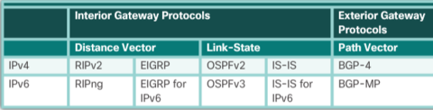
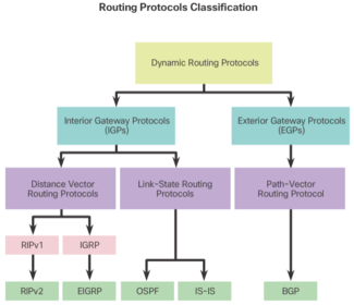
| Routing protocols can be classified into different groups according to their characteristics. Specifically, routing protocols can be classified by their: * Purpose - Interior Gateway Protocol (IGP) or Exterior Gateway Protocol (EGP) * Operation - Distance vector, link-state protocol, or path-vector protocol * Behavior - Classful (legacy) or classless protocol | |
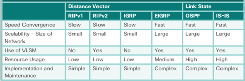
| For example, IPv4 routing protocols are classified as follows: * RIPv1 (legacy) - IGP, distance vector, classful protocol * IGRP (legacy) - IGP, distance vector, classful protocol developed by Cisco (deprecated from 12.2 IOS and later) * RIPv2 - IGP, distance vector, classless protocol | * EIGRP - IGP, distance vector, classless protocol developed by Cisco * OSPF - IGP, link-state, classless protocol * IS-IS - IGP, link-state, classless protocol * BGP - EGP, path-vector, classless protocol |
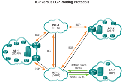
| An autonomous system (AS) is a collection of routers under a common administration such as a company or an organization. An AS is also known as a routing domain. Typical examples of an AS are a company’s internal network and an ISP’s network. * Interior Gateway Protocols (IGP) - Used for routing within an AS. It is also referred to as intra-AS routing. Companies, organizations, and even service providers use an IGP on their internal networks. IGPs include RIP, EIGRP, OSPF, and IS-IS. * Exterior Gateway Protocols (EGP) - Used for routing between AS. It is also referred to as inter-AS routing. Service providers and large companies may interconnect using an EGP. The Border Gateway Protocol (BGP) is the only currently-viable EGP and is the official routing protocol used by the Internet | |
| Distance vector means that routes are advertised by providing two characteristics: * Distance - Identifies how far it is to the destination network and is based on a metric such as the hop count, cost, bandwidth, delay, and more. * Vector - Specifies the direction of the next-hop router or exit interface to reach the destination. | There are four distance vector IPv4 IGPs: * RIPv1 - First generation legacy protocol * RIPv2 - Simple distance vector routing protocol * IGRP - First generation Cisco proprietary protocol (obsolete and replaced by EIGRP) * EIGRP - Advanced version of distance vector routing |
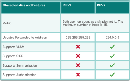
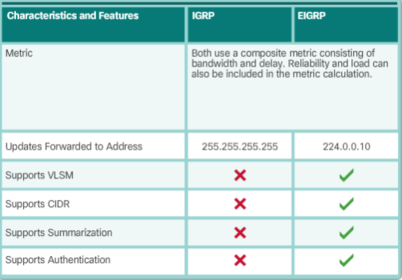
| The biggest distinction between classful and classless routing protocols is that classful routing protocols do not send subnet mask information in their routing updates. Classless routing protocols include subnet mask information in the routing updates. The fact that RIPv1 and IGRP do not include subnet mask information in their updates means that they cannot provide variable-length subnet masks (VLSMs) and classless interdomain routing (CIDR). | Classful routing protocols also create problems in discontiguous networks. A discontiguous network is when subnets from the same classful major network address are separated by a different classful network address |
| Speed of Convergence - Speed of convergence defines how quickly the routers in the network topology share routing information and reach a state of consistent knowledge. The faster the convergence, the more preferable the protocol. Routing loops can occur when inconsistent routing tables are not updated due to slow convergence in a changing network | |
| Distance vector routing protocols share updates between neighbors. Neighbors are routers that share a link and are configured to use the same routing protocol. The router is only aware of the network addresses of its own interfaces and the remote network addresses it can reach through its neighbors. Routers using distance vector routing are not aware of the network topology. RIP sends a periodic update to all of its neighbors every 30 seconds. RIP does this even if the topology has not changed; it continues to send updates. RIPv1 reaches all of its neighbors by sending updates to the all-hosts IPv4 address of 255.255.255.255, a broadcast. | The broadcasting of periodic updates is inefficient because the updates consume bandwidth and consume network device CPU resources. Every network device has to process a broadcast message. RIPv2 and EIGRP, instead, use multicast addresses so that only neighbors that need updates will receive them. EIGRP can also send a unicast message to only the affected neighbor. Additionally, EIGRP will only send an update when needed, instead of periodically. |
| The algorithm used for the routing protocols defines the following processes: * Mechanism for sending and receiving routing information * Mechanism for calculating the best paths and installing routes in the routing table * Mechanism for detecting and reacting to topology changes | RIP uses the "Bellman-Ford" algorithm as its routing algorithm. It is based on two algorithms developed in 1958 and 1956 by Richard Bellman and Lester Ford, Jr. IGRP and EIGRP use the "Diffusing Update Algorithm (DUAL)" routing algorithm developed by Dr. J.J. Garcia-Luna-Aceves at SRI International. |
| RIPv1 has the following key characteristics: * Routing updates are broadcasted (255.255.255.255) every 30 seconds. * The hop count is used as the metric for path selection. * A hop count greater than 15 hops is deemed infinite (too far). That 15th hop router would not propagate the routing update to the next router. | |
| RIPv2 included the following improvements: * Classless routing protocol - It supports VLSM and CIDR, because it includes the subnet mask in the routing updates. * Increased efficiency - It forwards updates to multicast address 224.0.0.9, instead of the broadcast address 255.255.255.255. * Reduced routing entries - It supports manual route summarization on any interface. | * Secure - It supports an authentication mechanism to secure routing table updates between neighbors. RIP updates are encapsulated into a UDP segment, with both source and destination port numbers set to UDP port 520. In 1997, the IPv6 enabled version of RIP was released. RIPng is based on RIPv2. It still has a 15 hop limitation and the administrative distance is 120. |
| The Interior Gateway Routing Protocol (IGRP) was the first proprietary IPv4 routing protocol developed by Cisco in 1984. It used the following design characteristics: * Bandwidth, delay, load, and reliability are used to create a composite metric. * Routing updates are broadcast every 90 seconds, by default. | |
| EIGRP also introduced: 1. Bounded triggered updates - It does not send periodic updates. Only routing table changes are propagated, whenever a change occurs. This reduces the amount of load the routing protocol places on the network. Bounded triggered updates means that EIGRP only sends to the neighbors that need it. It uses less bandwidth, especially in large networks with many routes. | 2. Hello keepalive mechanism - A small Hello message is periodically exchanged to maintain adjacencies with neighboring routers. This means a very low usage of network resources during normal operation, instead of the periodic updates. 3. Maintains a topology table - Maintains all the routes received from neighbors (not only the best paths) in a topology table. DUAL can insert backup routes into the EIGRP topology table. |
| EIGRP also introduced: 4. Rapid convergence - In most cases, it is the fastest IGP to converge because it maintains alternate routes, enabling almost instantaneous convergence. If a primary route fails, the router can use the alternate route identified. The switchover to the alternate route is immediate and does not involve interaction with other routers. | 5. Multiple network layer protocol support - EIGRP uses Protocol Dependent Modules (PDM), which means that it is the only protocol to include support for protocols other than IPv4 and IPv6, such as legacy IPX and AppleTalk. |
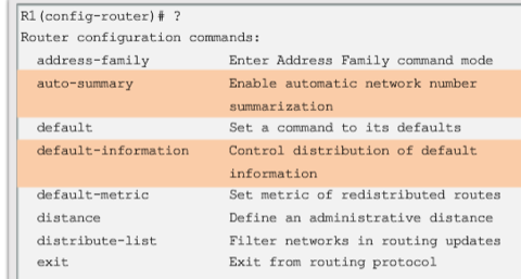
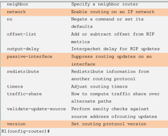
| By entering the RIP router configuration mode, the router is instructed to run RIP. But the router still needs to know which local interfaces it should use for communication with other routers, as well as which locally connected networks it should advertise to those routers. Note: If a subnet address is entered, the IOS automatically converts it to the classful network address. Remember RIPv1 is a classful routing protocol for IPv4. For example, entering the network 192.168.1.32 command would automatically be converted to network 192.168.1.0 in the running configuration file | |
| By default, when a RIP process is configured on a Cisco router, it is running RIPv1. However, even though the router only sends RIPv1 messages, it can interpret both RIPv1 and RIPv2 messages. A RIPv1 router ignores the RIPv2 fields in the route entry. | |
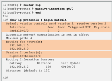
| By default, RIP updates are forwarded out all RIP enabled interfaces. However, RIP updates really only need to be sent out interfaces connecting to other RIP enabled routers Use the "passive-interface" router configuration command to prevent the transmission of routing updates through a router interface, but still allow that network to be advertised to other routers. The command stops routing updates out the specified interface. However, the network that the specified interface belongs to is still advertised in routing updates that are sent out other interfaces. As an alternative, all interfaces can be made passive using the "passive-interface" default command | |
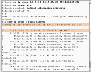
| To provide Internet connectivity to all other networks in the RIP routing domain, the default static route needs to be advertised to all other routers that use the dynamic routing protocol. The "default-information originate" router configuration command. This instructs R1 router to originate default information, by propagating the static default route in RIP updates. | |
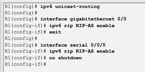
| Unlike RIPv2, RIPng is enabled on an interface and not in router configuration mode. In fact, there is no "network network-address" command available in RIPng. Instead, use the ipv6 rip domain-name enable interface configuration command. | |
| The process to propagate a default route in RIPng is identical to RIPv2 except that an IPv6 default static route must be specified. For example, assume that R1 had an Internet connection from a Serial 0/0/1 interface to IP address 2001:DB8:FEED:1::1/64. To propagate a default route, R3 would have to be configured with: * A default static route using the "ipv6 route 0::/0 2001:DB8:FEED:1::1" global configuration command. | * The "ipv6 rip domain-name default-information originate" interface configuration mode command. This instructs R3 to be the source of the default route information and propagate the default static route in RIPng updates sent out of the configured interface. |
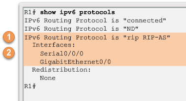
| The show ipv6 protocols command does not provide the same amount of information as its IPv4 counterpart. However, it does confirm the following parameters: 1. That RIPng routing is configured and running on router R1. 2. The interfaces configured with RIPng. | |
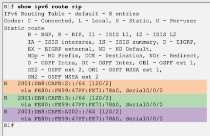
| This is because the metric (hop count) that is displayed in the IPv4 routing table is the number of hops required to reach the remote network (counting the next-hop router as the first hop). In RIPng, the sending router already considers itself to be one hop away; therefore, R2 advertises its LAN with a metric of 1. When R1 receives the update, it adds another hop count of 1 to the metric. Therefore, R1 considers the R2 LAN to be two hops away. Similarly it considers the R3 LAN to be three hops away. | |
| Link-state routing protocols are also known as shortest path first protocols and are built around: Edsger Dijkstra's shortest path first (SPF) algorithm. | * Open Shortest Path First (OSPF) * Intermediate System-to-Intermediate System (IS-IS) "router ospf (process-id)" global configuration command "network" command to advertise networks |
| In the figure, each path is labeled with an arbitrary value for cost. The cost of the shortest path for R2 to send packets to the LAN attached to R3 is 27. Each router determines its own cost to each destination in the topology. In other words, each router calculates the SPF algorithm and determines the cost from its own perspective. Note: The focus of this section is on cost, which is determined by the SPF tree. For this reason, the graphics throughout this section show the connections of the SPF tree, not the topology. All links are represented with a solid black line. | |
| All routers in an OSPF area will complete the following generic link-state routing process to reach a state of convergence: 1. Each router learns about its own links and its own directly connected networks. This is done by detecting that an interface is in the up state. 2. Each router is responsible for meeting its neighbors on directly connected networks. Link state routers do this by exchanging Hello packets with other link-state routers on directly connected networks. 3. Each router builds a Link-State Packet (LSP) containing the state of each directly connected link. This is done by recording all the pertinent information about each neighbor, including neighbor ID, link type, and bandwidth. | 4. Each router floods the LSP to all neighbors. Those neighbors store all LSPs received in a database. They then flood the LSPs to their neighbors until all routers in the area have received the LSPs. Each router stores a copy of each LSP received from its neighbors in a local database. 5. Each router uses the database to construct a complete map of the topology and computes the best path to each destination network. Like having a road map, the router now has a complete map of all destinations in the topology and the routes to reach them. The SPF algorithm is used to construct the map of the topology and to determine the best path to each network. |
| The link-state information includes: * The interface's IPv4 address and subnet mask * The type of network, such as Ethernet (broadcast) or Serial point-to-point link * The cost of that link * Any neighbor routers on that link Note: Cisco’s implementation of OSPF specifies the OSPF routing metric as the cost of the link based on the bandwidth of the outgoing interface. | |
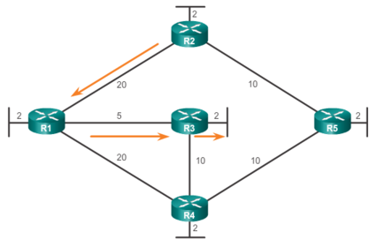
| The second step in the link-state routing process is that each router is responsible for meeting its neighbors on directly connected networks. Routers with link-state routing protocols use a Hello protocol to discover any neighbors on its links. A neighbor is any other router that is enabled with the same link-state routing protocol. EXAMPLE: R1 sends Hello packets out of its links (interfaces) to discover if there are any neighbors. R2, R3, and R4 reply to the Hello packet with their own Hello packets because these routers are configured with the same link-state routing protocol | There are no neighbors out the FastEthernet 0/0 interface. Because R1 does not receive a Hello on this interface, it does not continue with the link-state routing process steps for the FastEthernet 0/0 link. When two link-state routers learn that they are neighbors, they form an adjacency. These small Hello packets continue to be exchanged between two adjacent neighbors and serves as a keepalive function to monitor the state of the neighbor. If a router stops receiving Hello packets from a neighbor, that neighbor is considered unreachable and the adjacency is broken. |
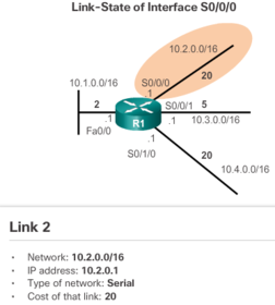
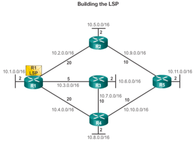
| The third step in the link-state routing process is that each router builds a link-state packet (LSP) containing the state of each directly connected link. After a router has established its adjacencies, it can build its LSPs that contain the link-state information about its links. A simplified version of the LSP from R1 displayed in the figure would contain the following: 1. R1; Ethernet network 10.1.0.0/16; Cost 2 2. R1 -> R2; Serial point-to-point network; 10.2.0.0/16; Cost 20 3. R1 -> R3; Serial point-to-point network; 10.3.0.0/16; Cost 5 4. R1 -> R4; Serial point-to-point network; 10.4.0.0/16; Cost 20 | |
| The fourth step in the link-state routing process is that each router floods the LSP to all neighbors, who then store all LSPs received in a database. Each router floods its link-state information to all other link-state routers in the routing area. Whenever a router receives an LSP from a neighboring router, it immediately sends that LSP out all other interfaces except the interface that received the LSP. This process creates a flooding effect of LSPs from all routers throughout the routing area. Remember that LSPs do not need to be sent periodically. An LSP only needs to be sent: * During initial startup of the routing protocol process on that router (e.g., router restart) | * Whenever there is a change in the topology (e.g., a link going down or coming up, a neighbor adjacency being established or broken) In addition to the link-state information, other information is included in the LSP, such as sequence numbers and aging information, to help manage the flooding process. This information is used by each router to determine if it has already received the LSP from another router or if the LSP has newer information than what is already contained in the link-state database. This process allows a router to keep only the most current information in its link-state database. |
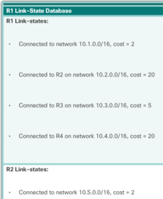
| The final step in the link-state routing process is that each router uses the database to construct a complete map of the topology and computes the best path to each destination network. Eventually, all routers receive an LSP from every other link-state router in the routing area. These LSPs are stored in the link-state database | |
| there are several advantages of link-state routing protocols compared to distance vector routing protocols. 1. Builds a Topological Map - Link-state routing protocols create a topological map, or SPF tree of the network topology. Because link-state routing protocols exchange link-states, the SPF algorithm can build an SPF tree of the network. Using the SPF tree, each router can independently determine the shortest path to every network. 2. Fast Convergence - When receiving an LSP, link-state routing protocols immediately flood the LSP out all interfaces except for the interface from which the LSP was received. In contrast, RIP needs to process each routing update and update its routing table before flooding them out other interfaces. | 3. Event-driven Updates - After the initial flooding of LSPs, link-state routing protocols only send out an LSP when there is a change in the topology. The LSP contains only the information regarding the affected link. Unlike some distance vector routing protocols, link-state routing protocols do not send periodic updates. 4. Hierarchical Design - Link-state routing protocols use the concept of areas. Multiple areas create a hierarchical design to networks, allowing for better route aggregation (summarization) and the isolation of routing issues within an area. |
| Link-state protocols also have a few disadvantages compared to distance vector routing protocols 1. Processing Requirements - Link-state protocols can also require more CPU processing than distance vector routing protocols. The SPF algorithm requires more CPU time than distance vector algorithms such as Bellman-Ford, because link-state protocols build a complete map of the topology. | 2. Memory Requirements - Link-state protocols require additional memory to create and maintain the link-state database and SPF tree. 3. Bandwidth Requirements - The flooding of link-state packets can adversely affect the available bandwidth on a network. This should only occur during initial startup of routers, but can also be an issue on unstable networks. |
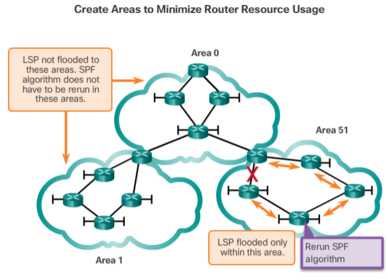
| Modern link-state routing protocols are designed to minimize the effects on memory, CPU, and bandwidth. The use and configuration of multiple areas can reduce the size of the link-state databases. Multiple areas can also limit the amount of link-state information flooding in a routing domain and send LSPs only to those routers that need them. When there is a change in the topology, only those routers in the affected area receive the LSP and run the SPF algorithm. This can help isolate an unstable link to a specific area in the routing domain. | |
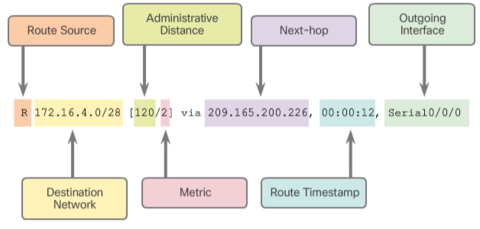
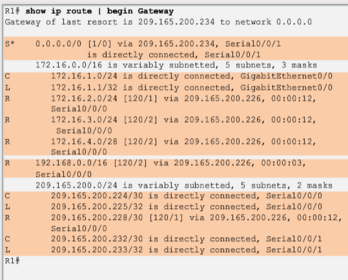
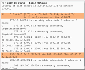
| The entry identifies the following information: * Route source - Identifies how the route was learned. * Destination network - Identifies the address of the remote network. * Administrative distance - Identifies the trustworthiness of the route source. * Metric - Identifies the value assigned to reach the remote network. Lower values indicate preferred routes. * Next hop - Identifies the IPv4 address of the next router to forward the packet to. * Route timestamp - Identifies from when the route was last heard. * Outgoing interface - Identifies the exit interface to use to forward a packet toward the final destination. | |
| The Cisco IP routing table is not a flat database. The routing table is actually a hierarchical structure that is used to speed up the lookup process when locating routes and forwarding packets. Within this structure, the hierarchy includes several levels. | Routes are discussed in terms of: * Ultimate route * Level 1 route * Level 1 parent route * Level 2 child routes |
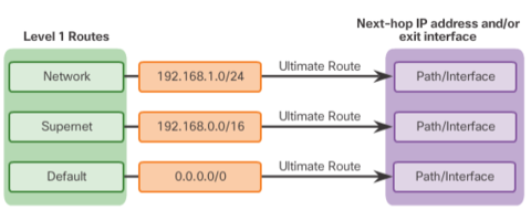
| An ultimate route is a routing table entry that contains either a next-hop IPv4 address or an exit interface. Directly connected, dynamically learned, and local routes are ultimate routes. | |
| A level 1 route is a route with a subnet mask equal to or less than the classful mask of the network address. * Network route - A network route that has a subnet mask equal to that of the classful mask. * Supernet route - A supernet route is a network address with a mask less than the classful mask, for example, a summary address. * Default route - A default route is a static route with the address 0.0.0.0/0. | |
| A level 1 route is a route with a subnet mask equal to or less than the classful mask of the network address. * Network route - A network route that has a subnet mask equal to that of the classful mask. * Supernet route - A supernet route is a network address with a mask less than the classful mask, for example, a summary address. * Default route - A default route is a static route with the address 0.0.0.0/0. | |
Want to create your own Flashcards for free with GoConqr? Learn more.