6023430
Description
Flashcards by John Dedios, updated more than 1 year ago
|
|
Created by John Dedios
over 9 years ago
|
|
| Question | Answer |
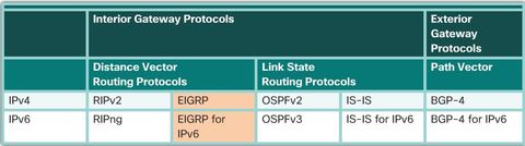
| Enhanced Interior Gateway Routing Protocol (EIGRP) is an advanced distance vector routing protocol developed by Cisco Systems. As the name suggests, EIGRP is an enhancement of another Cisco routing protocol IGRP (Interior Gateway Routing Protocol). IGRP is an older classful, distance vector routing protocol, now obsolete since IOS 12.3. | EIGRP is a distance vector routing protocol that includes features found in link-state routing protocols. EIGRP is suited for many different topologies and media. In a well-designed network, EIGRP can scale to include multiple topologies and can provide extremely quick convergence times with minimal network traffic. |
| Features of EIGRP EIGRP was initially released in 1992 as a proprietary protocol available only on Cisco devices. In 2013, Cisco released a basic functionality of EIGRP as an open standard to the IETF as an informational RFC. This means that other networking vendors can now implement EIGRP on their equipment to interoperate with both Cisco and non-Cisco routers running EIGRP. However, advanced features of EIGRP, such as EIGRP stub, needed for the Dynamic Multipoint Virtual Private Network (DMVPN) deployment, will not be released to the IETF. As an informational RFC, Cisco will continue to maintain control of EIGRP. | |
| Features of EIGRP 1. Diffusing Update Algorithm - As the computational engine that drives EIGRP, the Diffusing Update Algorithm (DUAL) resides at the center of the routing protocol. DUAL guarantees loop-free and backup paths throughout the routing domain. Using DUAL, EIGRP stores all available backup routes for destinations so that it can quickly adapt to alternate routes when necessary. | 2. Establishing Neighbor Adjacencies EIGRP establishes relationships with directly connected routers that are also enabled for EIGRP. Neighbor adjacencies are used to track the status of these neighbors. 3. Reliable Transport Protocol The Reliable Transport Protocol (RTP) is unique to EIGRP and provides delivery of EIGRP packets to neighbors. RTP and the tracking of neighbor adjacencies set the stage for DUAL. |
| Features of EIGRP 4. Partial and Bounded Updates EIGRP uses the terms, partial and bounded, when referring to its updates. Unlike RIP, EIGRP does not send periodic updates and route entries do not age out. * The term partial means that the update only includes information about the route changes, such as a new link or a link becoming unavailable. * The term bounded refers to the propagation of partial updates that are sent only to those routers that the changes affect. This minimizes the bandwidth that is required to send EIGRP updates. | 5. Equal and Unequal Cost Load Balancing EIGRP supports equal cost load balancing and unequal cost load balancing, which allows administrators to better distribute traffic flow in their networks. Note: EIGRP includes features of both link-state and distance vector routing protocols. However, EIGRP is still based on the key distance vector routing protocol principle, in which information about the rest of the network is learned from directly connected neighbors. |
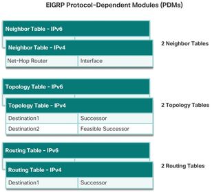
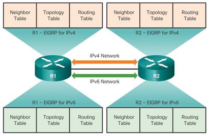
| Protocol Dependent Modules EIGRP has the capability for routing several different protocols including IPv4 and IPv6 using protocol-dependent modules (PDMs). PDMs are responsible for network layer protocol-specific tasks. ** An example is the EIGRP module that is responsible for sending and receiving EIGRP packets that are encapsulated in IPv4. This module is also responsible for parsing EIGRP packets and informing DUAL of the new information that is received. EIGRP asks DUAL to make routing decisions, but the results are stored in the IPv4 routing table. | |
| Protocol Dependent Modules PDMs are responsible for the specific routing tasks for each network layer protocol, including: * Maintaining the neighbor and topology tables of EIGRP routers that belong to that protocol suite * Building and translating protocol-specific packets for DUAL * Interfacing DUAL to the protocol-specific routing table | * Computing the metric and passing this information to DUAL * Implementing filtering and access lists * Performing redistribution functions to and from other routing protocols * Redistributing routes that are learned by other routing protocols |
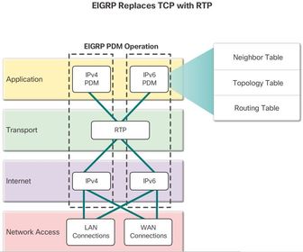
| Reliable Transport Protocol EIGRP uses Reliable Transport Protocol (RTP) for the delivery and reception of EIGRP packets. EIGRP was designed as a network layer independent routing protocol; because of this design EIGRP cannot use the services of UDP or TCP. * This allows EIGRP to be used for protocols other than those from the TCP/IP protocol suite, such as IPX and AppleTalk. | |
| Reliable Transport Protocol Although “reliable” is part of its name, RTP includes both reliable delivery and unreliable delivery of EIGRP packets, similar to TCP and UDP, respectively. Reliable RTP requires an acknowledgment to be returned by the receiver to the sender. An unreliable RTP packet does not require an acknowledgment. For example, an EIGRP update packet is sent reliably over RTP and requires an acknowledgment. An EIGRP Hello packet is also sent over RTP, but unreliably. This means that EIGRP Hello packets do not require an acknowledgment. | RTP can send EIGRP packets as unicast or multicast. * Multicast EIGRP packets for IPv4 use the reserved IPv4 multicast address 224.0.0.10. * Multicast EIGRP packets for IPv6 are sent to the reserved IPv6 multicast address FF02::A. |
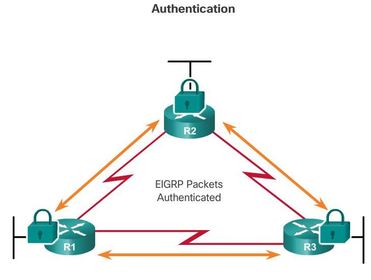
| Authentication It is a good practice to authenticate transmitted routing information. Doing so ensures that routers only accept routing information from other routers that have been configured with the same password or authentication information. ** Note: Authentication does not encrypt the EIGRP routing updates. | |
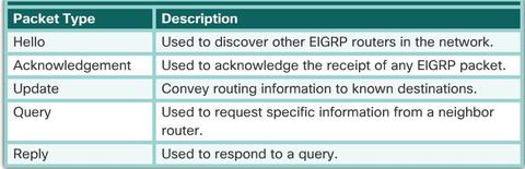
| EIGRP Packet Types EIGRP uses five different packet types, some in pairs. EIGRP packets are sent using either RTP reliable or unreliable delivery and can be sent as a unicast, multicast, or sometimes both. EIGRP packet types are also called EIGRP packet formats or EIGRP messages. | |
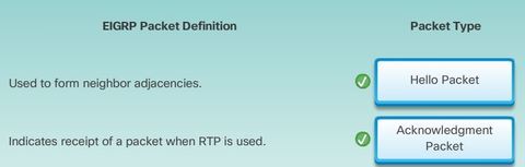
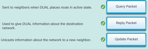
| EIGRP Packet Types 1. Hello packets - Used for neighbor discovery and to maintain neighbor adjacencies. * Sent with unreliable delivery * Multicast (on most network types) 2. Update packets - Propagates routing information to EIGRP neighbors. * Sent with reliable delivery * Unicast or multicast 3. Acknowledgment packets - Used to acknowledge the receipt of an EIGRP message that was sent using reliable delivery. | * Sent with unreliable delivery * Unicast 4. Query packets - Used to query routes from neighbors. * Sent with reliable delivery * Unicast or multicast 5. Reply packets -B9 Sent in response to an EIGRP query. * Sent with reliable delivery * Unicast |
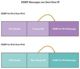
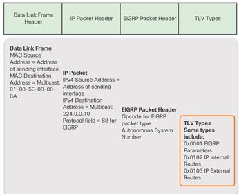
| EIGRP Packet Types Ej: shows that EIGRP messages are typically encapsulated in IPv4 or IPv6 packets. * EIGRP for IPv4 messages use IPv4 as the network layer protocol. The IPv4 protocol field uses 88 to indicate the data portion of the packet is an EIGRP for IPv4 message. EIGRP for IPv6 messages are encapsulated in IPv6 packets using the next header field of 88. Similar, to the protocol field for IPv4, the IPv6 next header field indicates the type of data carried in the IPv6 packet. | |
| EIGRP Hello Packets Hello packets are used by routers to form EIGRP neighbor adjacencies, also known as neighbor relationships. ** EIGRP also uses Hello packets to maintain established adjacencies. An EIGRP router assumes that as long as it receives Hello packets from a neighbor, the neighbor and its routes remain viable. | |
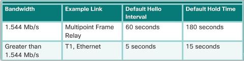
| EIGRP Hello Packets On most networks, EIGRP Hello packets are sent as multicast packets every five seconds. ** However, on multipoint, nonbroadcast multiple access (NBMA) networks, such as X.25, Frame Relay, and Asynchronous Transfer Mode (ATM) interfaces with access links of T1 (1.544 Mb/s) or slower, Hello packets are sent as unicast packets every 60 seconds. | EIGRP uses a Hold timer to determine the maximum time the router should wait to receive the next Hello before declaring that neighbor as unreachable. ** By default, the hold time is three times the Hello interval, or 15 seconds on most networks and 180 seconds on low-speed NBMA networks. If the hold time expires, EIGRP declares the route as down and DUAL searches for a new path by sending out queries. |
| EIGRP Update Packets ** EIGRP sends incremental updates only when the state of a destination changes. This may include when a new network becomes available, an existing network becomes unavailable, or a change occurs in the routing metric for an existing network. ** EIGRP uses the terms partial and bounded when referring to its updates. The term partial means that the update only includes information about the route changes. The term bounded refers to the propagation of partial updates that are sent only to those routers that the changes affect. | EIGRP Acknowledgment Packets EIGRP sends Acknowledgment (ACK) packets when reliable delivery is used. An EIGRP acknowledgment is an EIGRP Hello packet without any data. RTP uses reliable delivery for EIGRP update, query, and reply packets. EIGRP acknowledgment packets are always sent as an unreliable unicast. Unreliable delivery makes sense; otherwise, there would be an endless loop of acknowledgments. Note: Some documentation refers to the Hello and acknowledgment as a single type of EIGRP packet |
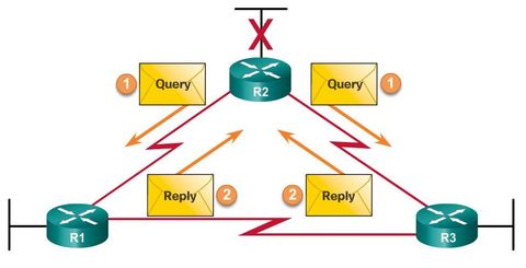
| EIGRP Query and Reply Packets 4. EIGRP Query Packets DUAL uses query and reply packets when searching for networks and other tasks Ej: R2 has lost connectivity to the LAN and it sends out queries to all EIGRP neighbors searching for any possible routes to the LAN. Because queries use reliable delivery, the receiving router must return an EIGRP acknowledgment. To keep this example simple, acknowledgments were omitted in the graphic. 5. EIGRP Reply Packets All neighbors must send a reply, regardless of whether or not they have a route to the downed network. | |
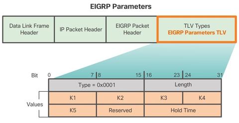
| Encapsulating EIGRP Messages This data field is called type, length, value (TLV). The types of TLVs relevant to this course are EIGRP parameters, IP internal routes, and IP external routes. ** The EIGRP packet header and TLV are then encapsulated in an IPv4 packet. In the IPv4 packet header, the protocol field is set to 88 to indicate EIGRP, and the IPv4 destination address is set to the multicast 224.0.0.10. If the EIGRP packet is encapsulated in an Ethernet frame, the destination MAC address is also a multicast address, 01-00-5E-00-00-0A. | |
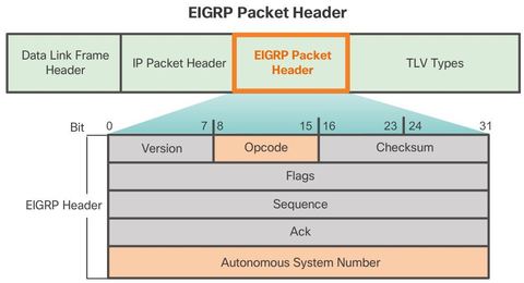
| EIGRP Packet Header and TLV * Opcode: EIGRP Packet Type: Update (1), Query (3), Reply (4), Hello (5) * Autonomous System Number: specifies the EIGRP routing process. Unlike RIP, multiple instances of EIGRP can run on a network; the autonomous system number is used to track each running EIGRP process. | |
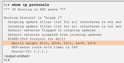
| EIGRP Packet Header and TLV * The EIGRP parameter’s message includes the weights that EIGRP uses for its composite metric. By default, only bandwidth and delay are weighted. Both are weighted equally; therefore, the K1 field for bandwidth and the K3 field for delay are both set to one (1). The other K values are set to zero (0). * The Hold Time is the amount of time the EIGRP neighbor receiving this message should wait before considering the advertising router to be down. | |
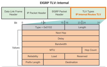
| EIGRP Packet Header and TLV The IP internal message is used to advertise EIGRP routes within an autonomous system. * Delay: Sum of delays in units of 10 microseconds from source to destination; 0xFFFFFFFF indicates unreachable route * Bandwidth: is the lowest configured bandwidth of any interface along the route. * The subnet mask is specified as the prefix length or the number of network bits in the subnet mask. For example, the prefix length for the subnet mask 255.255.255.0 is 24, because 24 is the number of network bits. | |
| EIGRP Packet Header and TLV * The Destination field: stores the address of the destination network. Although only 24 bits are shown in this figure, this field varies based on the value of the network portion of the 32-bit network address. For example, the network portion of 10.1.0.0/16 is 10.1; therefore, the Destination field stores the first 16 bits. Because the minimum length of this field is 24 bits, the remainder of the field is padded with zeros. If a network address is longer than 24 bits (192.168.1.32/27, for example), then the Destination field is extended for another 32 bits (for a total of 56 bits) and the unused bits are padded with zeros. | |
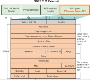
| EIGRP Packet Header and TLV The IP external message is used when external routes are imported into the EIGRP routing process. In this chapter, we will import or redistribute a default static route into EIGRP. Notice that the bottom half of the IP External Routes TLV includes all the fields used by the IP Internal TLV. ** Note: The maximum transmission unit (MTU) is not a metric used by EIGRP. The MTU is included in the routing updates, but it is not used to determine the routing metric. | |
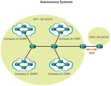
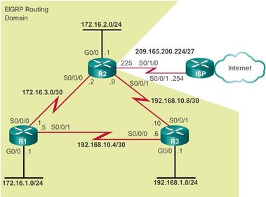
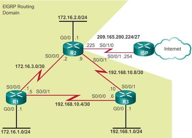
| Autonomous System Numbers EIGRP uses the "router eigrp (autonomous-system)" command to enable the EIGRP process. The autonomous system number referred to in the EIGRP configuration is not associated with the Internet Assigned Numbers Authority (IANA) globally assigned autonomous system numbers used by external routing protocols An IANA globally assigned autonomous system is a collection of networks under the administrative control of a single entity that presents a common routing policy to the Internet. In the figure, companies A, B, C, and D are all under the administrative control of ISP1. ISP1 presents a common routing policy for all of these companies when advertising routes to ISP2. | |
| Autonomous System Numbers The autonomous system number used for EIGRP configuration is only significant to the EIGRP routing domain. ** It functions as a process ID to help routers keep track of multiple, running instances of EIGRP. This is required because it is possible to have more than one instance of EIGRP running on a network. Each instance of EIGRP can be configured to support and exchange routing updates for different networks. | Global autonomous system numbers are assigned by IANA, the same authority that assigns IP address space. The local regional Internet registry (RIR) is responsible for assigning an autonomous system number to an entity from its block of assigned autonomous system numbers. Prior to 2007, autonomous system numbers were 16-bit numbers ranging from 0 to 65,535. Today, 32-bit autonomous system numbers are assigned increasing the number of available autonomous system numbers to over 4 billion. |
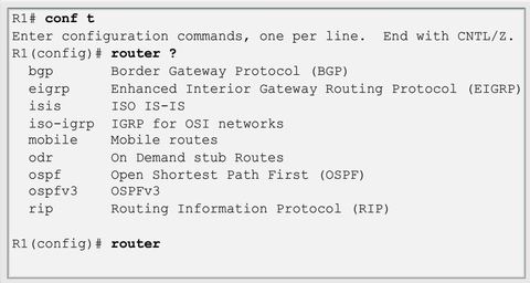
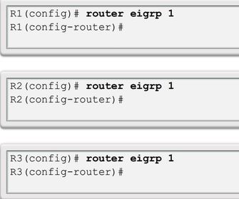
| The Router EIGRP Command The "router" global configuration mode command is used to begin the configuration of any dynamic routing protocol. Router(config)# router eigrp (autonomous-system) The autonomous-system argument can be assigned to any 16-bit value between the number 1 and 65,535. ** All routers within the EIGRP routing domain must use the same autonomous system number. | |
| The Router EIGRP Command Ej: ? command does not start the EIGRP process itself. The router does not start sending updates. Rather, this command only provides access to configure the EIGRP settings. To completely remove the EIGRP routing process from a device, use the no router eigrp autonomous-system global configuration mode command, which stops the EIGRP process and removes all existing EIGRP router configurations. | |
| Determining the Router ID is used to uniquely identify each router in the EIGRP routing domain. In EIGRP IPv4 implementations, the use of the router ID is not that apparent. EIGRP for IPv4 uses the 32-bit router ID to identify the originating router for redistribution of external routes. The need for a router ID becomes more evident in the discussion of EIGRP for IPv6 * While the router ID is necessary for redistribution, the details of EIGRP redistribution are beyond the scope of this curriculum. For purposes of this curriculum, it is only necessary to understand what the router ID is and how it is derived. | |
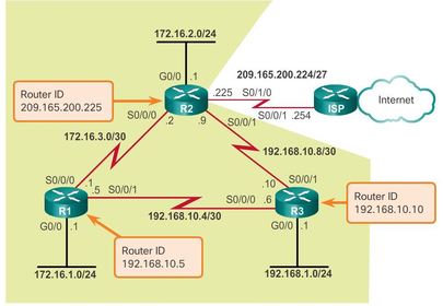
| Determining the Router ID Cisco routers derive the router ID based on three criteria, in the following precedence: 1. Use the IPv4 address configured with the eigrp router-id router configuration mode command. 2. If the router ID is not configured, the router chooses the highest IPv4 address of any of its loopback interfaces. 3. If no loopback interfaces are configured, the router chooses the highest active IPv4 address of any of its physical interfaces. | If the network administrator does not explicitly configure a router ID using the eigrp router-id command, EIGRP generates its own router ID using either a loopback or physical IPv4 address. ** A loopback address is a virtual interface and is automatically in the up state when configured. The interface does not need to be enabled for EIGRP, meaning that it does not need to be included in one of the EIGRP network commands. However, the interface must be in the up/up state. |
| Configuring the EIGRP Router ID Router(config)# router eigrp (autonomous-system) Router(config-router)# eigrp router-id (ipv4-address) The router ID should be a unique 32-bit number in the EIGRP routing domain; otherwise, routing inconsistencies can occur. | |
| Configuring the EIGRP Router ID ** Another option to specify the EIGRP router ID is to use an IPv4 loopback address. The advantage of using a loopback interface, instead of the IPv4 address of a physical interface, is that unlike physical interfaces, it cannot fail. There are no actual cables or adjacent devices on which the loopback interface depends for being in the up state. EIGRP chooses the highest IPv4 address of any of its loopback interfaces. The following commands are used to enable and configure a loopback interface: Router(config)# interface loopback (number) Router(config-if)# ip address (ipv4-address) (subnet-mask) | |
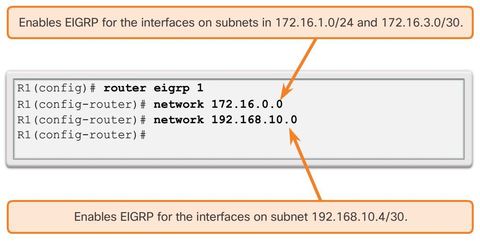
| The network command has the same function as in all IGP routing protocols. The network command in EIGRP: ** Enables any interface on this router that matches the network address in the network router configuration mode command to send and receive EIGRP updates. * The network of the interfaces is included in EIGRP routing updates. Router(config-router)# network (ipv4-network-addres) | By default, the "eigrp log-neighbor-changes" router configuration mode command is enabled. This command is used to: * Display any changes in EIGRP neighbor adjacencies. * Help verify neighbor adjacencies during configuration of EIGRP. * Advise the network administrator when any EIGRP adjacencies have been removed. |
| The network command has the same function as in all IGP routing protocols. The network command in EIGRP: ** Enables any interface on this router that matches the network address in the network router configuration mode command to send and receive EIGRP updates. * The network of the interfaces is included in EIGRP routing updates. Router(config-router)# network (ipv4-network-addres) | By default, the "eigrp log-neighbor-changes" router configuration mode command is enabled. This command is used to: * Display any changes in EIGRP neighbor adjacencies. * Help verify neighbor adjacencies during configuration of EIGRP. * Advise the network administrator when any EIGRP adjacencies have been removed. |
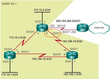
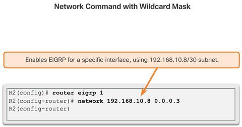
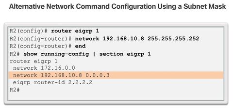
| The Network Command and Wildcard Mask By default, when using the network command and an IPv4 network address, such as 172.16.0.0, all interfaces on the router that belong to that classful network address are enabled for EIGRP. However, there may be times when the network administrator does not want to include all interfaces within a network when enabling EIGRP. | To configure EIGRP to advertise specific subnets only, use the wildcard-mask option with the network command: Router(config-router)# network (network-address) [wildcard-mask] |
| The Network Command and Wildcard Mask Some IOS versions also let you enter the subnet mask instead of a wildcard mask. Ej: shows an example of configuring the same S0/0/1 interface on R2, but this time using a subnet mask in the network command. ** However, if the subnet mask is used, the IOS converts the command to the wildcard-mask format within the configuration. This is verified in the show running-config output of Ej. | |
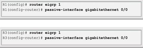
| Passive Interface There are two primary reasons for enabling the passive-interface command: 1. To suppress unnecessary update traffic, such as when an interface is a LAN interface, with no other routers connected 2. To increase security controls, such as preventing unknown rogue routing devices from receiving EIGRP updates * Router(config)# router eigrp (as-number) * Router(config-router)# passive-interface (interface-type) (interface-number) Note: To configure all interfaces as passive, use the "passive-interface default" command. To disable an interface as passive, use the "no passive-interface interface-type interface-number" command. | |
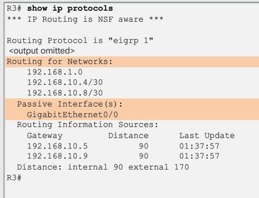
| Passive Interface An example of using the passive interface to increase security controls is when a network must connect to a third-party organization, for which the local administrator has no control, such as when connecting to an ISP network. In this case, the local network administrator would need to advertise the interface link through their own network, but would not want the third-party organization to receive or send routing updates to the local routing device, as this is a security risk. * Ej: ? To verify whether any interface on a router is configured as passive | |
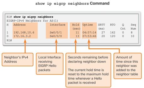
| Verifying EIGRP: Examining Neighbors Ej: ? command to view the neighbor table and verify that EIGRP has established an adjacency with its neighbors * H column - Lists the neighbors in the order that they were learned. * Smooth Round Trip Timer (SRTT) and Retransmission Timeout (RTO) - Used by RTP to manage reliable EIGRP packets. * Queue Count - Should always be zero. If more than zero, then EIGRP packets wait to be sent. * Sequence Number - Used to track updates, queries, and reply packets. | |
| Verifying EIGRP: Examining Neighbors "show ip eigrp neighbors" command is very useful for verifying and troubleshooting EIGRP. If a neighbor is not listed after adjacencies have been established with a router’s neighbors, check the local interface to ensure it is activated with the show ip interface brief command. If the interface is active, try pinging the IPv4 address of the neighbor. If the ping fails, it means that the neighbor interface is down and must be activated. | If the ping is successful and EIGRP still does not see the router as a neighbor, examine the following configurations: * Are both routers configured with the same EIGRP autonomous system number? * Is the directly connected network included in the EIGRP network statements? |
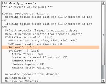
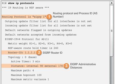
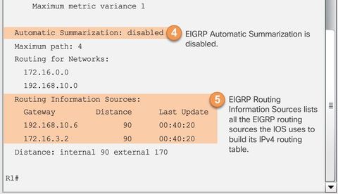
| 4. By default, EIGRP does not automatically summarize networks. Subnets are included in the routing updates. ** Note: Prior to IOS 15, EIGRP automatic summarization was enabled by default. ** The output from the show ip protocols command is useful in debugging routing operations. Information in the Routing Information Sources field can help identify a router suspected of delivering bad routing information. The Routing Information Sources field lists all the EIGRP routing sources the Cisco IOS software uses to build its IPv4 routing table. | |
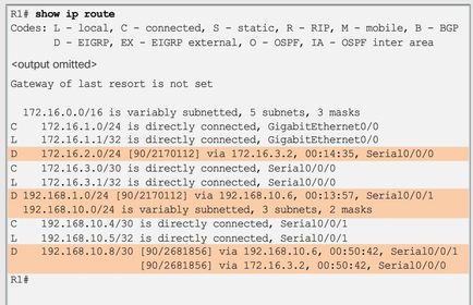
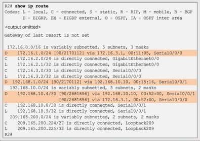
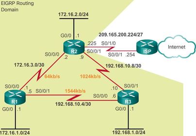
| Verifying EIGRP: Examine the IPv4 routing table Router(config-router)# no auto-summary (For older 15. Versions ) The letter D was used to represent EIGRP because the protocol is based upon the DUAL algorithm. Ej: R1 has two paths to the 192.168.10.8/30 network, because its cost or metric to reach that network is the same or equal using both routers. These are known as equal cost routes. R1 uses both paths to reach this network, which is known as load balancing. | |
| EIGRP Neighbor Adjacency ** The goal of any dynamic routing protocol is to learn about remote networks from other routers and to reach convergence in the routing domain EIGRP uses Hello packets to establish and maintain neighbor adjacencies. For two EIGRP routers to become neighbors, several parameters between the two routers must match | ** For example, two EIGRP routers must use the same EIGRP metric parameters and both must be configured using the same autonomous system number. Each EIGRP router maintains a neighbor table, which contains a list of routers on shared links that have an EIGRP adjacency with this router. The neighbor table is used to track the status of these EIGRP neighbors. |
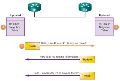
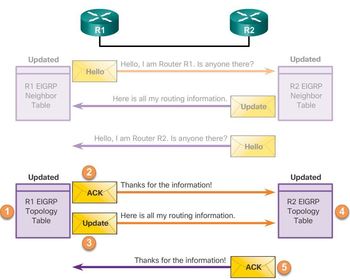
| EIGRP Neighbor Adjacency 1. A new router (R1) comes up on the link and sends an EIGRP Hello packet through all of its EIGRP-configured interfaces. 2. Router R2 receives the Hello packet on an EIGRP-enabled interface. R2 replies with an EIGRP update packet that contains all the routes it has in its routing table, except those learned through that interface (split horizon). However, the neighbor adjacency is not established until R2 also sends an EIGRP Hello packet to R1. 3. After both routers have exchanged Hellos, the neighbor adjacency is established. R1 and R2 update their EIGRP neighbor tables adding the adjacent router as a neighbor. | |
| EIGRP Topology Table EIGRP updates contain networks that are reachable from the router sending the update. As EIGRP updates are exchanged between neighbors, the receiving router adds these entries to its EIGRP topology table. Each EIGRP router maintains a topology table for each routed protocol configured, such as IPv4 and IPv6. The topology table includes route entries for every destination that the router learns from its directly connected EIGRP neighbor | |
| EIGRP Topology Table 1. R1 receives the EIGRP update from neighbor R2 and includes information about the routes that the neighbor is advertising, including the metric to each destination. R1 adds all update entries to its topology table. The topology table includes all destinations advertised by neighboring (adjacent) routers and the cost (metric) to reach each network. 2. EIGRP update packets use reliable delivery; therefore, R1 replies with an EIGRP acknowledgment packet informing R2 that it has received the update. | 3. R1 sends an EIGRP update to R2 advertising the routes that it is aware of, except those learned from R2 (split horizon). 4. R2 receives the EIGRP update from neighbor R1 and adds this information to its own topology table. 5. R2 responds to the R1’s EIGRP update packet with an EIGRP acknowledgment. |
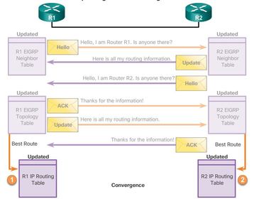
| EIGRP Convergence 1. After receiving the EIGRP update packets from R2, using the information in the topology table, R1 updates its IP routing table with the best path to each destination, including the metric and the next-hop router. 2. Similar to R1, R2 updates its IP routing table with the best path routes to each network. At this point, EIGRP on both routers is considered to be in the converged state. | |
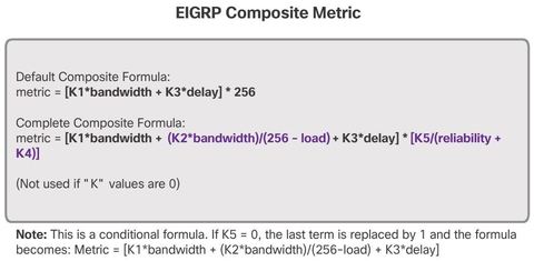
| EIGRP Composite Metric By default, EIGRP uses the following values in its composite metric to calculate the preferred path to a network: * Bandwidth - The slowest bandwidth among all of the outgoing interfaces, along the path from source to destination. * Delay - The cumulative (sum) of all interface delay along the path (in tens of microseconds). Note: Although the MTU is included in the routing table updates, it is not a routing metric used by EIGRP. | The following values can be used, but are not recommended, because they typically result in frequent recalculation of the topology table: * Reliability - Represents the worst reliability between the source and destination, which is based on keepalives. * Load - Represents the worst load on a link between the source and destination, which is computed based on the packet rate and the configured bandwidth of the interface. |
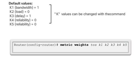
| EIGRP Composite Metric Ej: ? command is used to verify the k values. ** The metric calculation method (k values) and the EIGRP autonomous system number must match between EIGRP neighbors. If they do not match, the routers do not form an adjacency. Router(config-router)# metric weights (tos k1 k2 k3 k4 k5) If one router has modified the metric weights and another router has not, an adjacency does not form. | |
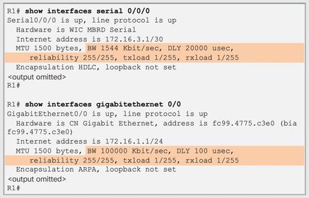
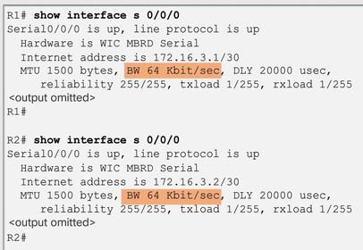
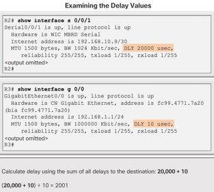
| Examining the Metric Values Ej: ? command displays interface information, including the parameters used to compute the EIGRP metric * BW - Bandwidth of the interface (in kilobits per second). * DLY - Delay of the interface (in microseconds). ** Reliability - Reliability of the interface as a fraction of 255 (255/255 is 100% reliability), calculated as an exponential average over five minutes. By default, EIGRP does not include its value in computing its metric. ** Txload, Rxload - Transmit and receive load on the interface as a fraction of 255 (255/255 is completely saturated), calculated as an exponential average over five minutes. By default, EIGRP does not include its value in computing its metric. | |
| Bandwidth Metric The bandwidth metric is a static value used by some routing protocols, such as EIGRP and OSPF, to calculate their routing metric. The bandwidth is displayed in kilobits per second (kb/s). ** Most serial interfaces use the default bandwidth value of 1544 kb/s or 1,544,000 b/s (1.544 Mb/s). This is the bandwidth of a T1 connection. However, some serial interfaces use a different default bandwidth value | |
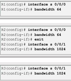
| Configuring the Bandwidth Parameter Router(config-if)# bandwidth (kilobits-bandwidth-value) Use the no bandwidth command to restore the default value. * The default value of the bandwidth may or may not reflect the actual physical bandwidth of the interface. If actual bandwidth of the link differs from the default bandwidth value, the bandwidth value should be modified. | |
| Bandwidth Metric Ej: ? command to verify the new bandwidth parameters It is important to modify the bandwidth metric on both sides of the link to ensure proper routing in both directions. Modifying the bandwidth value does not change the actual bandwidth of the link. The bandwidth command only modifies the bandwidth metric used by routing protocols, such as EIGRP and OSPF | |
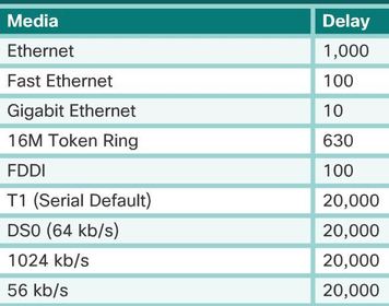
| Delay Metric Delay is the measure of the time it takes for a packet to traverse a route. The delay (DLY) metric is a static value based on the type of link to which the interface is connected and is expressed in microseconds. ** Delay is not measured dynamically. In other words, the router does not actually track how long packets take to reach the destination. The delay value, much like the bandwidth value, is a default value that can be changed by the network administrator. | |
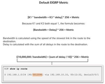
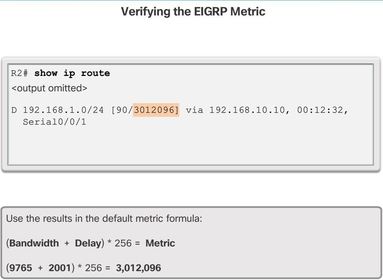
| How to Calculate the EIGRP Metric Step 1. Determine the link with the slowest bandwidth. Use that value to calculate bandwidth (10,000,000/bandwidth). Step 2. Determine the delay value for each outgoing interface on the way to the destination. Add the delay values and divide by 10 (sum of delay/10). Step 3. This composite metric produces a 24-bit value; however, EIGRP uses a 32-bit value. Multiplying the 24-bit value with 256 extends the composite metric into 32 bits. Therefore, add the computed values for bandwidth and delay, and multiply the sum by 256 to obtain the EIGRP metric. | |
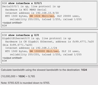
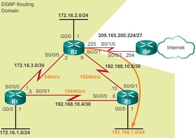
| Calculating the EIGRP Metric - Bandwidth EIGRP divides a reference bandwidth value of 10,000,000 by the interface bandwidth value in kb/s. This results in higher bandwidth values receiving a lower metric and lower bandwidth values receiving a higher metric. Ej: 10,000,000 is divided by 1,024. If the result is not a whole number, then the value is rounded down. In this case, 10,000,000 divided by 1,024 equals 9,765.625. The .625 is dropped to yield 9,765 for the bandwidth portion of the composite metric | |
| Calculating the EIGRP Metric - Delay EIGRP uses the sum of all delays to the destination. The Serial 0/0/1 interface on R2 has a delay of 20,000 microseconds. The Gigabit 0/0 interface on R3 has a delay of 10 microseconds. The sum of these delays is divided by 10. In the example, (20,000+10)/10 results in a value of 2,001 for the delay portion of the composite metric. | |
| Introduction to DUAL Distance vector routing protocols, such as RIP, prevent routing loops with hold-down timers and split horizon. Although EIGRP uses both of these techniques, it uses them somewhat differently; the primary way that EIGRP prevents routing loops is with the DUAL algorithm. | The DUAL algorithm is used to obtain loop-freedom at every instance throughout a route computation. This allows all routers involved in a topology change to synchronize at the same time. Routers that are not affected by the topology changes are not involved in the recomputation. This method provides EIGRP with faster convergence times than other distance vector routing protocols. |
| Introduction to DUAL The decision process for all route computations is done by the DUAL Finite State Machine (FSM). An FSM is a workflow model, similar to a flow chart that is composed of the following: * A finite number of stages (states) * Transitions between those stages * Operations | The DUAL FSM tracks all routes, uses EIGRP metrics to select efficient, loop-free paths, and identify the routes with the least-cost path to be inserted into the routing table. ** Recomputation of the DUAL algorithm can be processor-intensive. EIGRP avoids recomputation whenever possible by maintaining a list of backup routes that DUAL has already determined to be loop-free. If the primary route in the routing table fails, the best backup route is immediately added to the routing table. |
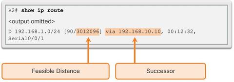
| Successor and Feasible Distance * A successor is a neighboring router that is used for packet forwarding and is the least-cost route to the destination network. The IP address of a successor is shown in a routing table entry right after the word via. * FD is the lowest calculated metric to reach the destination network. FD is the metric listed in the routing table entry as the second number inside the brackets. As with other routing protocols, this is also known as the metric for the route. | |
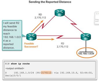
| Feasible Successors, Feasibility Condition, and Reported Distance An FS is a neighbor that has a loop-free backup path to the same network as the successor, and it satisfies the Feasibility Condition (FC). ** The FC is met when a neighbor’s Reported Distance (RD) to a network is less than the local router’s feasible distance to the same destination network. If the reported distance is less, it represents a loop-free path. The reported distance is simply an EIGRP neighbor’s feasible distance to the same destination network. The reported distance is the metric that a router reports to a neighbor about its own cost to that network. | |
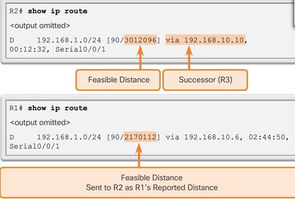
| Feasible Successors, Feasibility Condition, and Reported Distance Ej: R1’s feasible distance to 192.168.1.0/24 is 2,170,112. * R1 reports to R2 that its FD to 192.168.1.0/24 is 2,170,112. * From R2’s perspective, 2,170,112 is R1’s RD. R2 uses this information to determine if R1 meets the FC and, therefore, can be an FS. | |
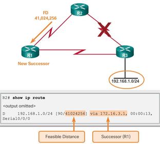
| Feasible Successors, Feasibility Condition, and Reported Distance Ej: R1 is now an FS for R2 to the 192.168.1.0/24 network. If there is a failure in R2’s path to 192.168.1.0/24 via R3 (successor), then R2 immediately installs the path via R1 (FS) in its routing table. * R1 becomes the new successor for R2’s path to this network, | |
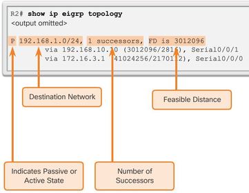
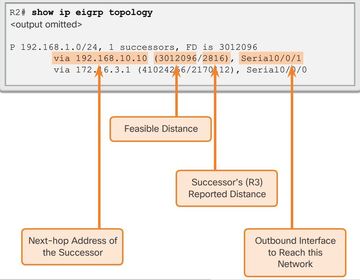
| Ej: ? the topology table displays: ** P - Route in the passive state. When DUAL is not performing its diffusing computations to determine a path for a network, the route is in a stable mode, known as the passive state. If DUAL recalculates or searches for a new path, the route is in an active state and displays an A. All routes in the topology table should be in the passive state for a stable routing domain. * 1 successors - Displays the number of successors for this network. If there are multiple equal cost paths to this network, there are multiple successors. * FD is 3012096 - FD, the EIGRP metric to reach the destination network | |
| Ej: ? the topology table displays: the first subentry in the output shows the successor: * via 192.168.10.10 - Next-hop address of the successor, R3. This address is shown in the routing table. * 3012096 - FD to 192.168.1.0/24. It is the metric shown in the IP routing table. * 2816 - RD of the successor and is R3’s cost to reach this network. | |
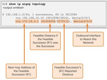
| Ej: ? the topology table displays: the second subentry shows the FS, R1 (if there is not a second entry, then there are no FSs): * via 172.16.3.1 - Next-hop address of the FS, R1. * 41024256 - R2’s new FD to 192.168.1.0/24, if R1 became the new successor and would be the new metric displayed in the IP routing table. * 2170112 - RD of the FS, or R1’s metric to reach this network. RD must be less than the current FD of 3,012,096 to meet the FC. | |
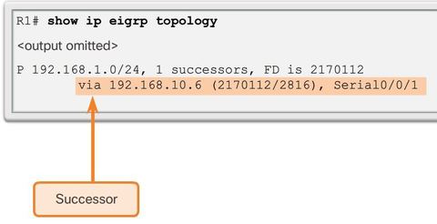
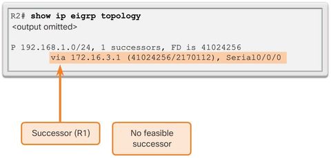
| Topology Table: No Feasible Successor ** The IP routing table only includes the best path, the successor. To see if there are any FSs, we must examine the EIGRP topology table. The topology table in Figure only shows the successor 192.168.10.6, which is R3. There are no FSs. By looking at the actual physical topology or network diagram, it is obvious that there is a backup route to 192.168.1.0/24 through R2. R2 is not an FS because it does not meet the FC. Ej: Although, looking at the topology, it is obvious that R2 is a backup route, EIGRP does not have a map of the network topology. EIGRP is a distance vector routing protocol and only knows about remote network information through its neighbors. | |
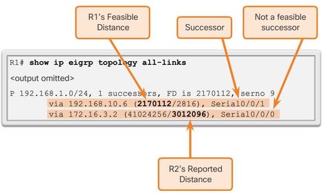
| Topology Table: No Feasible Successor Ej: ? command shows all possible paths to a network, including successors, FSs, and even those routes that are not FSs whether they satisfy the FC or not. ** Even though R2 looks like a viable backup path to 192.168.1.0/24, R1 has no idea that the path is not a potential loop back through itself. EIGRP is a distance vector routing protocol, without the ability to see a complete, loop-free topological map of the network. | |
| Topology Table: No Feasible Successor Ej: DUAL’s method of guaranteeing that a neighbor has a loop-free path is that the neighbor’s metric must satisfy the FC. By ensuring that the RD of the neighbor is less than its own FD, the router can assume that this neighboring router is not part of its own advertised route; thus, always avoiding the potential for a loop. R2 can be used as a successor if R3 fails; however, there is a longer delay before adding it to the routing table. Before R2 can be used as a successor, DUAL must do further processing. | |
| DUAL Finite State Machine (FSM) The centerpiece of EIGRP is DUAL and its EIGRP route-calculation engine. The actual name of this technology is DUAL Finite State Machine (FSM). * An FSM is an abstract machine, not a mechanical device with moving parts. FSMs define a set of possible states that something can go through, what events cause those states, and what events result from those states. Designers use FSMs to describe how a device, computer program, or routing algorithm reacts to a set of input events. "debug eigrp fsm" | |
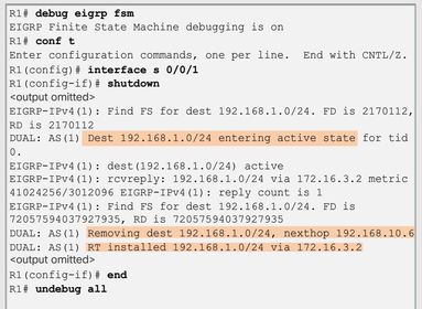
| DUAL: Feasible Successor Ej: To understand how DUAL can use a FS when the path using the successor is no longer available, a link failure is simulated between R2 and R3. Before simulating the failure, DUAL debugging must be enabled using the debug eigrp fsm command on R2, as shown in Figure 3. A link failure is simulated using the shutdown command on the Serial 0/0/1 interface on R2. | |
| DUAL: Feasible Successor Ej: the topology table for R2 now shows R1 as the successor and there are no new FSs. If the link between R2 and R3 is made active again, then R3 returns as the successor and R1 once again becomes the FS. | |
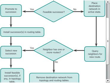
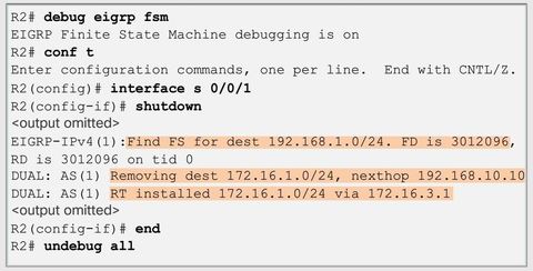
| DUAL: No Feasible Successor Ej: When the successor is no longer available and there is no feasible successor, DUAL puts the route into an active state. DUAL sends EIGRP queries asking other routers for a path to the network. Other routers return EIGRP replies, letting the sender of the EIGRP query know whether or not they have a path to the requested network. If none of the EIGRP replies have a path to this network, the sender of the query does not have a route to this network . R2 replies with a path to this network, which becomes the new successor and is installed into the routing table. | |
| EIGRP for IPv6 Similar to its IPv4 counterpart, EIGRP for IPv6 exchanges routing information to populate the IPv6 routing table with remote prefixes. * EIGRP for IPv6 was made available in Cisco IOS, Release 12.4(6)T. | |
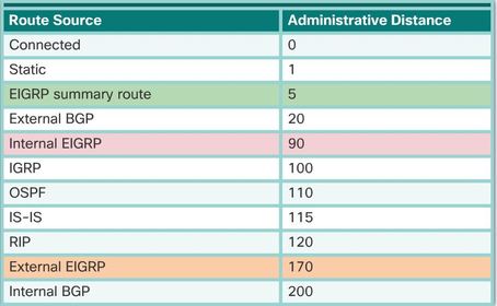
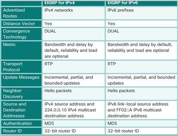
| Comparing EIGRP for IPv4 and IPv6 * Distance vector - Both protocols use the same administrative distances. * Transport protocol - The Reliable Transport Protocol (RTP) is responsible for guaranteed delivery of EIGRP packets to all neighbors * Update messages - Both EIGRP for IPv4 and IPv6 send incremental updates when the state of a destination changes. The terms, partial and bounded, are used when referring to updates for both protocols. * Source and destination addresses - EIGRP for IPv6 messages are sourced using the IPv6 link-local address of the exit interface | |
| IPv6 Link-local Addresses ** IPv6 link-local addresses are ideal for this purpose. An IPv6 link-local address enables a device to communicate with other IPv6-enabled devices on the same link and only on that link (subnet). Packets with a source or destination link-local address cannot be routed beyond the link from where the packet originated. Note: IPv6 link-local addresses are in the FE80::/10 range. The /10 indicates that the first 10 bits are 1111 1110 10xx xxxx, which results in the first hextet having a range of 1111 1110 1000 0000 (FE80) to 1111 1110 1011 1111 (FEBF). | EIGRP for IPv6 messages are sent using: * Source IPv6 address - This is the IPv6 link-local address of the exit interface. * Destination IPv6 address - When the packet needs to be sent to a multicast address, it is sent to the IPv6 multicast address FF02::A, the all-EIGRP-routers with link-local scope. If the packet can be sent as a unicast address, it is sent to the link-local address of the neighboring router. |
| Configuring IPv6 Link-local Addresses * Because EIGRP for IPv4 and IPv6 use the same metrics, modifying the bandwidth parameters influences both routing protocols. Link-local addresses are automatically created when an IPv6 global unicast address is assigned to the interface. Global unicast addresses are not required on an interface; however, IPv6 link-local addresses are. Unless configured manually, Cisco routers create the link-local address using FE80::/10 prefix and the EUI-64 process | ** EUI-64 involves using the 48-bit Ethernet MAC address, inserting FFFE in the middle and flipping the seventh bit. For serial interfaces, Cisco uses the MAC address of an Ethernet interface. A router with several serial interfaces can assign the same link-local address to each IPv6 interface, because link-local addresses only need to be local on the link. Because IPv6 routing protocols use IPv6 link-local addresses for unicast addressing and next hop address information in the routing table, it is common practice to make it an easily recognizable address. Configuring the link-local address manually provides the ability to create an address that is recognizable and easier to remember. |
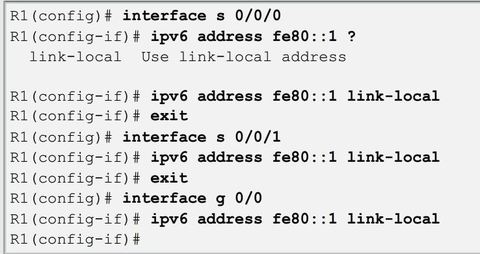
| Configuring IPv6 Link-local Addresses Link-local addresses can be configured manually using the same interface configuration mode command used to create IPv6 global unicast addresses, but with different parameters: Router(config-if)# ipv6 address (link-local-address) link-local A link-local address has a prefix within the range FE80 to FEBF. When an address begins with this hextet (16-bit segment), the link-local keyword must follow the address. * Use Exit before configuring the next interface | |
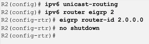
| Configuring the EIGRP for IPv6 Routing Process Ej: ? global configuration mode command enables IPv6 routing on the router. This command is required before any IPv6 routing protocol can be configured. Router(config)# ipv6 router eigrp (autonomous-system) Router(config-rtr)# eigrp router-id (32 bit value) ** By default, the EIGRP for IPv6 process is in a shutdown state. The no shutdown command is required to activate the EIGRP for IPv6 process ** Both the no shutdown command and a router ID are required for the router to form neighbor adjacencies. | |
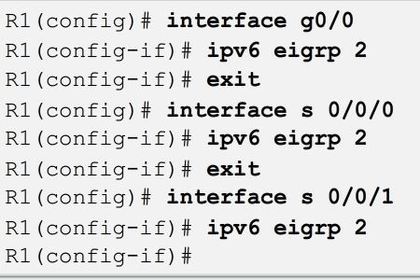
| ipv6 eigrp Interface Command Instead of using the network router configuration mode command to specify matching interface addresses, EIGRP for IPv6 is configured directly on the interface. * Use the following interface configuration mode command to enable EIGRP for IPv6 on an interface: Router(config-if)# ipv6 eigrp (autonomous-system) * "passive-interface" the same as IPv4 | |
| ipv6 eigrp Interface Command Instead of using the network router configuration mode command to specify matching interface addresses, EIGRP for IPv6 is configured directly on the interface. * Use the following interface configuration mode command to enable EIGRP for IPv6 on an interface: Router(config-if)# ipv6 eigrp (autonomous-system) | |
| ipv6 eigrp Interface Command "passive-interface" the same as IPv4 | |
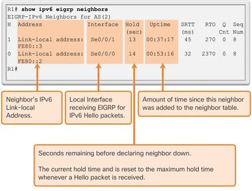
| Verifying EIGRP for IPv6: Examining Neighbors Ej: ? command to view the neighbor table and verify that EIGRP for IPv6 has established an adjacency with its neighbors. * H column - Lists the neighbors in the order they were learned. * Hold - Current hold time. When a Hello packet is received, this value is reset to the maximum hold time for that interface and then counts down to zero. If zero is reached, the neighbor is considered down. | |
| Verifying EIGRP for IPv6: Examining Neighbors Ej: ? command to view the neighbor table and verify that EIGRP for IPv6 has established an adjacency with its neighbors. * SRTT and RTO - Used by RTP to manage reliable EIGRP packets. * Queue Count - Should always be zero. If it is more than zero, then EIGRP packets are waiting to be sent. * Sequence Number - Used to track updates, queries, and reply packets. | |
| Verifying EIGRP for IPv6: Examining Neighbors The show ipv6 eigrp neighbors command is useful for verifying and troubleshooting EIGRP for IPv6. ** If an expected neighbor is not listed, ensure that both ends of the link are up/up using the show ipv6 interface brief command. The same requirements exist for establishing neighbor adjacencies with EIGRP for IPv6 as it does for IPv4. | If both sides of the link have active interfaces, check to see: * Are both routers configured with the same EIGRP autonomous system number? * Is the interface enabled for EIGRP for IPv6 with the correct autonomous system number? |
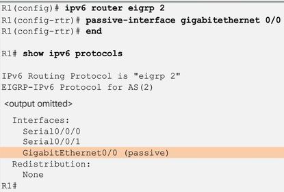
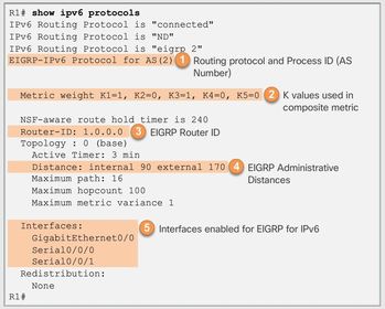
| Verifying EIGRP for IPv6: show ip protocols Command Ej: ? command displays the parameters and other information about the state of any active IPv6 routing protocol processes currently configured on the router. The Interfaces section shows which interfaces EIGRP for IPv6 have been enabled. This is useful in verifying that EIGRP is enabled on all of the appropriate interfaces with the correct autonomous system number. | |
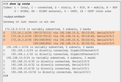
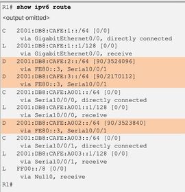
| Verifying EIGRP for IPv6: Examine the IPv6 Routing Table Ej: All three routes are using router R3 as the next-hop router (successor). Notice that the routing table uses the link-local address as the next-hop address. Because each router has had all its interfaces configured with a unique and distinguishable link-local address, it is easy to recognize that the next-hop router via FE80::3 is router R3. | |
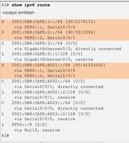
| Verifying EIGRP for IPv6: Examine the IPv6 Routing Table Ej: ? displays the routing table for R3. Notice that R3 has two equal cost paths to the 2001:DB8:CAFE:A001::/64. One path is via R1 at FE80::1 and the other path is via R2 at FE80::2. |
Want to create your own Flashcards for free with GoConqr? Learn more.