6494182
Description
Flashcards by John Dedios, updated more than 1 year ago
|
|
Created by John Dedios
over 9 years ago
|
|
| Question | Answer |
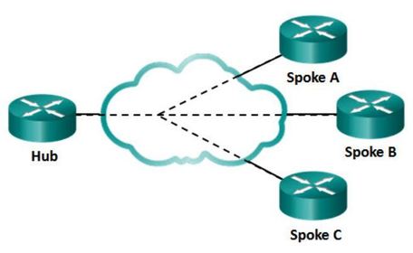
| WAN Topologies - Hub-and-Spoke If a private network connection between multiple sites is required, then a point-to-point topology with multiple point-to-point circuits is one option. Each point-to-point circuit requires its own dedicated hardware interface which will require multiple routers with multiple WAN interface cards. This can be expensive. A less expensive option is a point-to-multipoint topology (Figure), also known as a hub and spoke topology. With a hub-and-spoke topology a single interface to the hub can be shared by all spoke circuits. For example, spoke sites can be interconnected through the hub site using virtual circuits and routed subinterfaces at the hub. A hub-and-spoke topology is also an example of a single-homed topology. | |
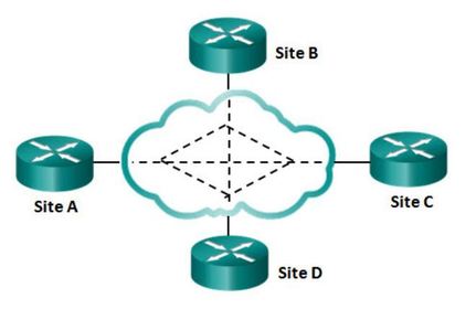
| WAN Topologies - Full Mesh One of the disadvantages of hub-and-spoke topologies is that all communication has to go through the hub. With a full mesh topology (Figure ) using virtual circuits, any site can communicate directly with any other site. The disadvantage here is the large number of virtual circuits that need to be configured and maintained. | |
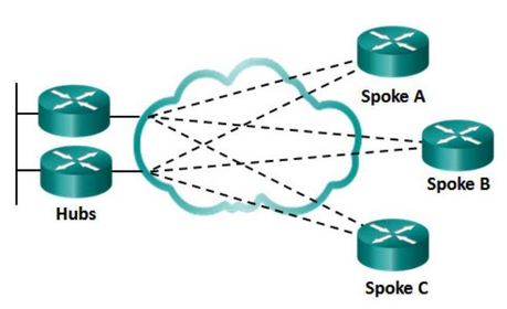
| WAN Topologies - Dual-homed A dual-homed topology provides redundancy The disadvantage to dual-homed topologies is that they are more expensive to implement than single-homed topologies. This is because they require additional networking hardware, like additional routers and switches. Dual-homed topologies are also more difficult to implement because they require additional, and more complex, configurations. However, the advantage of dual-homed topologies is that they offer enhanced network redundancy, load balancing, distributed computing or processing, and the ability to implement backup service provider connections. | |
| Dynamic Multipoint VPN (DMVPN) is a Cisco software solution for building multiple VPNs in an easy, dynamic, and scalable manner DMVPN is built using the following technologies: - Next Hop Resolution Protocol (NHRP) - Multipoint Generic Routing Encapsulation (mGRE) tunnels - IP Security (IPsec) encryption | |
| DMVPN is built using the following technologies: 1. Next Hop Resolution ProtocolNHRP is a Layer 2 resolution and caching protocol similar to Address Resolution Protocol (ARP). NHRP creates a distributed mapping database of public IP addresses for all tunnel spokes. NHRP is a client server protocol consisting of the NHRP hub known as the Next Hop Server (NHS), and the NHRP spokes known as the Next Hop Clients (NHC). | 2. Generic Routing Encapsulation (GRE) is a tunneling protocol developed by Cisco that can encapsulate a wide variety of protocol packet types inside IP tunnels. An mGRE tunnel interface allows a single GRE interface to support multiple IPsec tunnels. With mGRE, dynamically allocated tunnels are created through a permanent tunnel source at the hub and dynamically allocated tunnel destinations, created as necessary, at the spokes. This reduces the size and simplifies the complexity of the configuration. 3. Like other VPN types, DMVPN relies on IPsec to provide secure transport of private information over public networks, such as the Internet. |
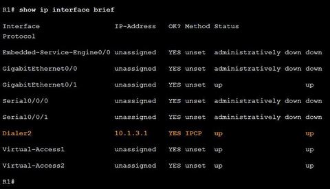
| PPPoE Verification Commands Ej: ? command is issued on R1 to verify the IPv4 address automatically assigned to the dialer interface by the ISP router. the customer’s router is connected to the ISP router using DSL. Both routers have been configured for PPPoE. | |
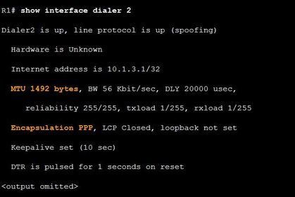
| PPPoE Verification Commands Ej: ? command on R1, verifies the MTU and PPP encapsulation configured on the dialer interface. | |
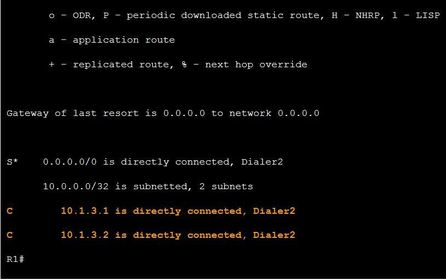
| PPPoE Verification Commands Ej: show ip route Notice that two /32 host routes for 10.0.0.0 have been installed in R1’s routing table. The first host route is for the address assigned to the dialer interface. The second host route is the IPv4 address of the ISP. The installation of these two host routes is the default behavior for PPPoE. | |
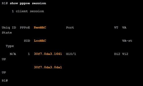
| PPPoE Verification Commands Ej: ? command is used to display information about currently active PPPoE sessions. The output displays the local and remote Ethernet MAC addresses of both routers. The Ethernet MAC addresses can be verified by using the show interfaces command on each router. | |
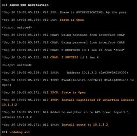
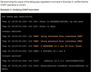
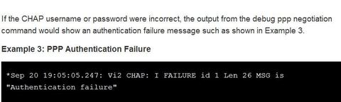
| PPPoE Negotiation Ej: ? Verify PPP negotiation, it displays part of the debug output after R1’s G0/1 interface has been enabled. There are four main points of failure in a PPP negotiation: - No response from the remote device (the ISP) - Link Control Protocol (LCP) not open - Authentication failure - IP Control Protocol (IPCP) failure | |
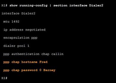
| PPPoE Authentication Ej: ? After confirming with the ISP that they use CHAP, verify that the CHAP username and password are correct. Example shows the CHAP configuration on the dialer2 interface. | |
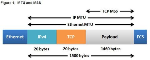
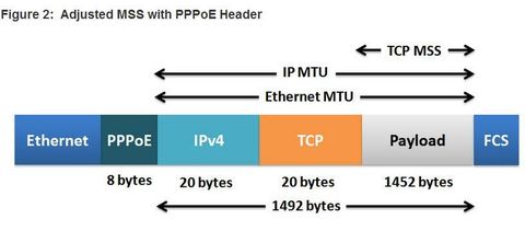
| PPPoE MTU Size Accessing some web pages might be a problem with PPPoE. When the client requests a web page, a TCP 3-way handshake occurs between the client and the web server. During the negotiation, the client specifies the value of its TCP maximum segment size (MSS). The TCP MSS is the maximum size of the data portion in the TCP segment. ** A host determines the value of its MSS field by subtracting the IP and TCP headers from the Ethernet maximum transmission unit (MTU). On an Ethernet interface, the default MTU is 1500 bytes. Subtracting the IPv4 header of 20 bytes and the TCP header of 20 bytes, the default MSS size will be 1460 bytes | |
| PPPoE MTU Size The default MSS size is 1460 bytes, when the default MTU is 1500 bytes. ** However, PPPoE supports an MTU of only 1492 bytes in order to accommodate the additional 8-byte PPPoE header You can verify the PPPoE MTU size in running configuration: R1# show running-config | section interface Dialer2 ** This disparity between the host and PPPoE MTU size can cause the router to drop 1500-byte packets and terminate TCP sessions over the PPPoE network. | |
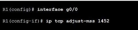
| PPPoE MTU Size Ej: ? interface command helps prevent TCP sessions from being dropped by adjusting the MSS value during the TCP 3-way handshake. ** In most cases, the optimum value for the max-segment-size argument is 1452 bytes. Example this configuration on R1’s LAN interface | |
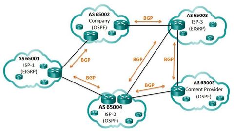
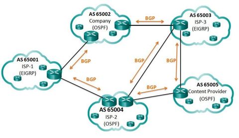
| IGP and EGP Routing Protocols IGPs are used to exchange routing information within a company network or an autonomous system (AS). Border Gateway Protocol (BGP) is an Exterior Gateway Protocol (EGP) used for the exchange of routing information between autonomous systems, such as ISPs, companies, and content providers (e.g., YouTube, NetFlix, etc.). In BGP, every AS is assigned a unique 16-bit or 32-bit AS number which uniquely identifies it on the Internet. | Note: There are also private AS numbers. BGP updates are encapsulated over TCP on port 179. Therefore, BGP inherits the connection-oriented properties of TCP, which ensures that BGP updates are transmitted reliably. ** IGP routing protocols are used to route traffic within the same organization and administered by a single organization. In contrast, BGP is used to route between networks administered by two different organizations. BGP is used by an AS to advertise its networks and in some cases, networks that it learned about from other autonomous systems, to the rest of the Internet. |
| IGP and EGP Routing Protocols Internal routing protocols use a specific metric, such as OSPF’s cost, for determining the best paths to destination networks. BGP does not use a single metric like IGPs. BGP routers exchange several path attributes including a list of AS numbers (hop by hop) necessary to reach a destination network. Ej: AS 65002 may use the AS-path of 65003 and 65005 to reach a network within the content provider AS 65005. ** BGP is known as a path vector routing protocol. Note: AS-path is one of several attributes that may be used by BGP to determine best path. | |
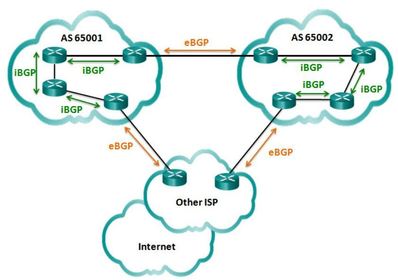
| eBGP and iBGP Two routers exchanging BGP routing information are known as BGP peers there are two types of BGP: - External BGP (eBGP) – External BGP is the routing protocol used between routers in different autonomous systems. - Internal BGP (iBGP) - Internal BGP is the routing protocol used between routers in the same AS. Note: There are some differences in how BGP operates depending on whether the two routers are eBGP peers or iBGP peers | |
| When to use BGP The use of BGP is most appropriate when an AS has connections to multiple autonomous systems. This is known as multi-homed. Ej: Each AS is multi-homed because each AS has connections to at least two other autonomous systems or BGP peers. A misconfiguration of a BGP router could have negative effects throughout the entire Internet. | |
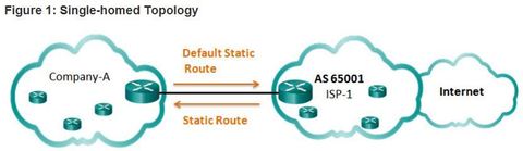
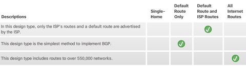
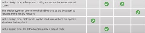
| When not to use BGP BGP should not be used when at least one of the following conditions exist: - There is a single connection to the Internet or another AS. This is known as single-homed. In this case, Company-A may run an IGP with the ISP or, Company-A and the ISP will each use static routes, Although it is recommended only in unusual situations, for the purposes of this course, you will configure single-homed BGP. - When there is a limited understanding of BGP. A misconfiguration of a BGP router can have far reaching affects beyond the local AS, negatively impacting routers throughout the Internet. Note: There are some single-homed situations where BGP may be appropriate, such as the need for a specific routing policy | |
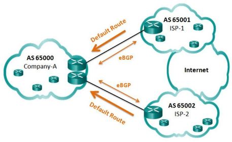
| BGP Options 1. Default Route Only ISPs advertise a default route to Company-A,The arrows indicate that the default is configured on the ISPs, not on the Company-A. ** This is the simplest method to implement BGP. However, because the company only receives a default route from both ISPs, sub-optimal routing may occur. For example, Company-A may choose to use ISP-1’s default route when sending packets to a destination network in ISP-2’s AS. | |
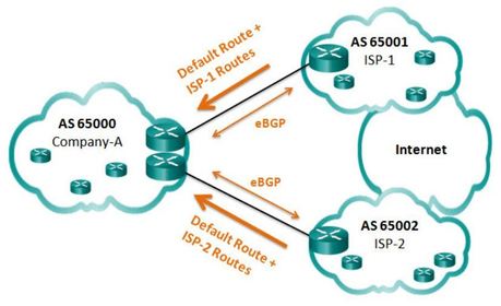
| BGP Options 2. Default Route and ISP Routes ISPs advertise their default route and their network to Company-AThis option allows Company-A to forward traffic to the appropriate ISP for networks advertised by that ISP. For example, Company-A would choose ISP-1 for networks advertised by ISP-1. For all other networks, one of the two default routes can be used, which means sub-optimal routing may still occur for all other Internet routes. | |
| BGP Options 3. All Internet Routes ISPs advertise all Internet routes to Company-A Because Company-A receives all Internet routes from both ISPs, Company-A can determine which ISP to use as the best path to forward traffic for any network. Although this solves the issue of sub-optimal routing, the Company-A’s BGP router must contain all Internet routes, which would currently include routes to over 550,000 networks. | |
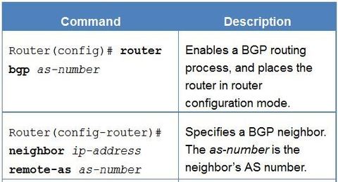
| To implement eBGP for this course, you will need to complete the following tasks: | Step 1: Enable BGP routing. Step 2: Configure BGP neighbor(s) (peering). Step 3: Advertise network(s) originating from this AS. |
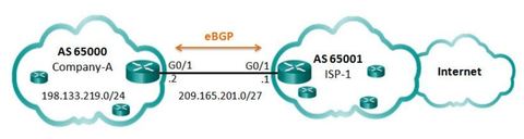
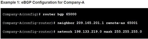
| BGP Sample Configuration Using eBGP, Company-A in AS 65000 will advertise its 198.133.219.0/24 network to ISP-1 at AS 65001. ISP-1 will advertise a default route in its eBGP updates to Company-A. Note: BGP is usually not necessary in single-homed AS. It is used here to provide a simple configuration example. | |
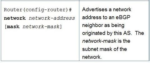
| BGP Sample Configuration ** The "mask" option must be used when the network being advertised is different than its classful equivalent. In this example, the 198.133.219.0/24 is equivalent to a class C network. Class C networks have a /24 subnet mask, so in this case the mask option is not required. If Customer-A was advertising the 198.133.0.0/16 network, then the mask option would be required. Otherwise BGP would advertise the network with a /24 classful mask. ** Note: In contrast to an IGP protocol, the network-address used in the network command does not have to be a directly connected network. The router only needs to have a route to this network in its routing table. | |
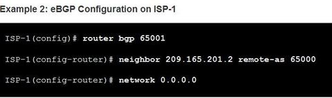
| BGP Sample Configuration A router can belong to only a single AS, so only a single BGP process can run on a router. Ej: Notice how the network 0.0.0.0 command is used to advertise a default network to Company-A. Note: Although the network 0.0.0.0 command is a valid BGP configuration option, there are better ways to advertise a default route in eBGP. | |
| Verify eBGP Ej: ? Verify routes advertised by the BGP neighbor are present in the IPv4 routing table. | |
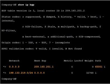
| Verify eBGP Ej: ? Verify that received and advertised IPv4 networks are in the BGP table. The first entry 0.0.0.0 with a next hop of 209.165.201.1 is the default route advertised by ISP-1. The AS path displays the single AS of 65001 because the 0.0.0.0/0 network advertised by ISP-1, originated from the same AS. Most BGP table entries show multiple autonomous system numbers in the path, listing the sequence of AS numbers required to reach the destination network. The second entry 198.133.219.0/24 is the network advertised by the Company-A router to ISP-1. The next hop address of 0.0.0.0 indicates that the 198.133.219.0/24 network originated from this router. | |
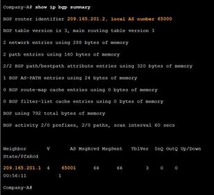
| Verify eBGP Ej: ? Verify IPv4 BGP neighbors and other BGP information such as router’s local AS number Also The address and AS number of the remote BGP neighbor is shown at the bottom of the output. | |
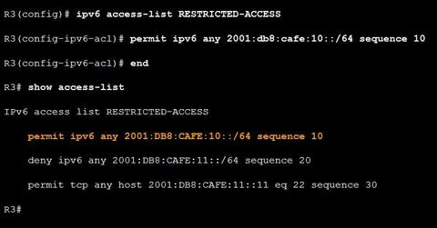
| Troubleshooting IPv6 ACL - Scenario 2 The first permit statement should allow access to the :10 network. However, the administrator configured a host statement and did not specify a prefix. In this case, only access to the 2001:DB8:CAFE:10:: host is allowed. Ej: To correct this issue, remove the host argument and change the prefix to /64. You can do this without removing the ACL by replacing the ACE using the sequence number 10 | |
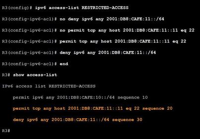
| Troubleshooting IPv6 ACL - Scenario 2 The second error in the ACL is the order of the next two statements. The policy specifies that hosts on the R3 LAN should be able to SSH into host 2001:DB8:CAFE:11::11. However, the deny statement for :11 network is listed before the permit statement. Therefore, all attempts to access the :11 network are denied before the statement permitting SSH access can be evaluated. After a match is made, no further statements are analyzed. Ej: To correct this issue, you will need to remove the statements first, and then enter them in the correct order | |
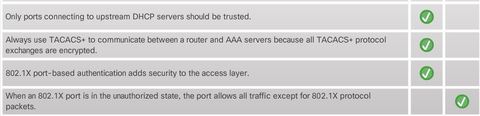
| DHCP Snooping A DHCP spoofing attack occurs when a rogue DHCP server is connected to the network and provides false IP configuration parameters to legitimate clients. ** DHCP spoofing is dangerous because clients can be leased IP information such as malicious DNS server addresses, malicious default gateways and malicious IP assignments. | DHCP snooping builds and maintains a database called the DHCP Snooping Binding Database (also known as the DHCP Snooping Binding Table). This database includes the client MAC address, IP address, DHCP lease time, binding type, VLAN number, and interface information on each untrusted switch port or interface. The network administrator must define what ports are to be trusted. By combining the information in the DHCP Snooping Binding Database with the trusted ports, the switch is able to filter DHCP messages from untrusted sources. |
| DHCP Snooping When DHCP snooping is enabled on an interface or VLAN, and a switch receives a DHCP packet on an untrusted port, the switch compares the source packet information with that held in the DHCP Snooping Binding Database. The switch will deny packets containing any of the following information: | * Unauthorized DHCP server messages coming from an untrusted port * Unauthorized DHCP client messages not adhering to the DHCP Snooping Binding Database or rate limits * DHCP relay-agent packets that include option-82 information coming from an untrusted port. ** Note: Option 82 provides additional security and is used to send information about DHCP clients to the DHCP server. However, an untrusted port should not be receiving option-82 packets. |
| DHCP Snooping ** In a large network, the DHCP Snooping Binding Database may take time to build after it is enabled. For example, it could take 2 days for DHCP snooping to complete the database if DHCP lease time is 4 days. DHCP snooping recognizes two types of ports: | 1. Trusted DHCP ports - Only ports connecting to upstream DHCP servers should be trusted. These ports should lead to legitimate DHCP servers replying with DHCP offer and DHCP Ack messages. Trusted ports must be explicitly identified in the configuration. 2. Untrusted ports - These ports connect to hosts that should not be providing DHCP server messages. By default, all switch ports are untrusted. |
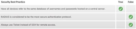
| AAA with RADIUS and TACACS+ To keep malicious users from gaining access to sensitive network equipment and services, administrators must enable access control. Access control limits who or what can use specific resources. ** It also limits the services or options that are available after access is granted. | Whether TACACS+ or RADIUS is selected depends on the needs of the organization. ** For example, a large ISP might select RADIUS because it supports the detailed accounting required for billing users. ** An organization with various user groups might select TACACS+ because it requires authorization policies to be applied on a per-user or per-group basis. |
| AAA with RADIUS and TACACS+ There are different methods of implementing authentication on a Cisco device, and each method offers varying levels of security. The following describes two common methods: 1. Simple password authentication – This involves using the "password" and "login" line configuration commands to protect the console, vty lines, and aux ports. ** Unfortunately this method is also the weakest and least secure method because it provides no accountability. For instance, anyone with the password can gain entry to the device and alter the configuration. | 2. Local database authentication – This involves creating local user accounts with the "username (name) secret (password)" global configuration command and then configuring the "login local" line configuration command on the console, VTY, and aux ports. ** This provides additional security, because an attacker is required to know a username and a password. It also provides more accountability, because the username is recorded when a user logs in. |
| AAA with RADIUS and TACACS+ However, the local database method does not scale well beyond a few networking devices because user accounts must be configured locally on each device. This is not suitable in a large enterprise environment with multiple routers and switches to manage. ** Additionally, the local database configuration provides no fallback authentication method. For example, what if the administrator forgets the username and password for that device? With no backup method available for authentication, password recovery becomes the only option. | A better and much more scalable solution is to have all devices refer to a database of usernames and passwords hosted on a central server. To support this, Cisco devices support the Authentication, Authorization, and Accounting (AAA) framework to help secure device access. Two AAA authentication protocols are supported on Cisco devices: - Terminal Access Controller Access-Control System Plus (TACACS+, pronounced as “tack-axe plus”) - Remote Authentication Dial-In User Service (RADIUS) |
| AAA with RADIUS and TACACS+ ** RADIUS does not encrypt user names, accounting information, or any other information carried in the RADIUS message. These are three critical factors for Terminal Access Controller Access-Control System Plus (TACACS+, pronounced as “tack-axe plus”): | * Separates authentication and authorization * Encrypts all communication * Utilizes TCP port 49 |
| AAA with RADIUS and TACACS+ ** RADIUS does not encrypt user names, accounting information, or any other information carried in the RADIUS message. These are four critical factors for Remote Authentication Dial-In User Service (RADIUS): | * Combines RADIUS authentication and authorization as one process * Encrypts only the password * Utilizes UDP * Supports remote-access technologies, 802.1X, and Session Initiation Protocol (SIP) |
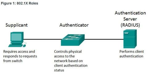
| 802.1X The IEEE 802.1X standard defines a port-based access control and authentication protocol that restricts unauthorized workstations from connecting to a LAN through publicly accessible switch ports. The authentication server authenticates each workstation that is connected to a switch port before making available any services offered by the switch or the LAN 1. Client (Supplicant) - This is usually the 802.1X enabled port on the device that requests access to LAN and switch services and then responds to requests from the switch. In Figure , the device is a PC running 802.1X-compliant client software. | |
| 802.1X - Roles 2. Switch (Authenticator) - Controls physical access to the network based on the authentication status of the client. The switch acts as an intermediary (proxy) between the client and the authentication server. It requests identifying information from the client, verifies that information with the authentication server, and relays a response to the client. ** The switch uses a RADIUS software agent, which is responsible for encapsulating and de-encapsulating the EAP (Extensible Authentication Protocol) frames and interacting with the authentication server. | |
| 802.1X - Roles 3. Authentication server - Performs the actual authentication of the client. The authentication server validates the identity of the client and notifies the switch whether the client is authorized to access the LAN and switch services. ** Because the switch acts as the proxy, the authentication service is transparent to the client. The RADIUS security system with EAP extensions is the only supported authentication server. | |
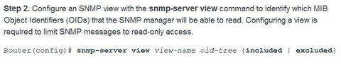
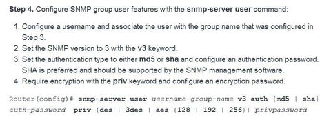
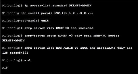
| SNMPv3 Configuration Steps EJ: a standard ACL named PERMIT-ADMIN is configured to permit only the 192.168.1.0/24 network. All hosts attached to this network will be allowed to access the SNMP agent running on R1. An SNMP view is named SNMP-RO and is configured to include the entire iso tree from the MIB. On a production network, the network administrator would probably configure this view to include only the MIB OIDs that were necessary for monitoring and managing the network. | |
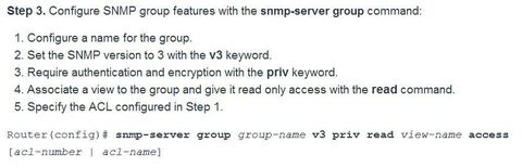
| SNMPv3 Configuration Steps EJ: An SNMP group is configured with the name ADMIN. SNMP is set to version 3 with authentication and encryption required. The group is allowed read-only access to the view (SNMP-RO). Access for the group is limited by the PERMIT-ADMIN ACL. An SNMP user, BOB, is configured as a member of the group ADMIN. SNMP is set to version 3. Authentication is set to use SHA, and an authentication password is configured. Although R1 supports up to AES 256 encryption, the SNMP management software only supports AES 128. Therefore, the encryption is set to AES 128 and an encryption password is configured. | |
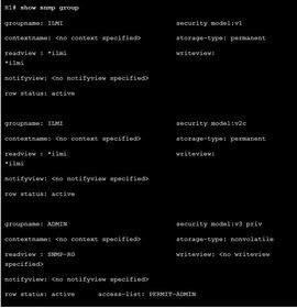
| SNMPv3 Verification Ej: ? command to display information about each SNMP group in the network Use the ping command to verify connectivity between agents and clients. | |
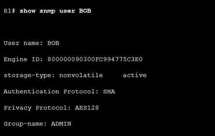
| SNMPv3 Verification Ej: ? command to display information about the configured characteristics of an SNMP user Use the ping command to verify connectivity between agents and clients. | |
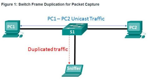
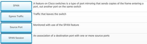
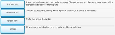
| Port Mirroring What if a network administrator wanted to capture packets from many other key devices and not just the local NIC? The basic operation of a modern switched network disables the packet analyzer ability to capture traffic from other sources. For instance, a user running Wireshark can only capture traffic going to their NIC. They cannot capture traffic between another host and a server. ** The solution to this dilemma is to enable port mirroring. The port mirroring feature allows a switch to copy and send Ethernet frames from specific ports to the destination port connected to a packet analyzer | |
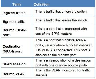
| Local SPAN ** The Switched Port Analyzer (SPAN) feature on Cisco switches is a type of port mirroring that sends copies of the frame entering a port, out another port on the same switch. ** It is common to find a device running a packet analyzer, an Intrusion Detection System (IDS), or an Intrusion Prevention System (IPS) connected to that port. | |
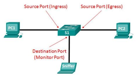
| Local SPAN A SPAN session is the association between source ports (or VLANs) and a destination port. Traffic entering or leaving the source port (or VLAN) is replicated by the switch on the destination port. ** Although SPAN can support multiple source ports under the same session or an entire VLAN as the traffic source, a SPAN session does not support both. Both Layer 2 and Layer 3 ports can be configured as source ports. | |
| Local SPAN The SPAN feature is said to be local when the monitored ports are all located on the same switch as the destination port. This feature is in contrast to Remote SPAN (RSPAN). ** There are three important things to consider when configuring SPAN: | 1. The destination port cannot be a source port, and the source port cannot be a destination port. 2. The number of destination ports is platform-dependent. Some platforms allow for more than one destination port. 3. The destination port is no longer a normal switch port. Only monitored traffic passes through that port. |
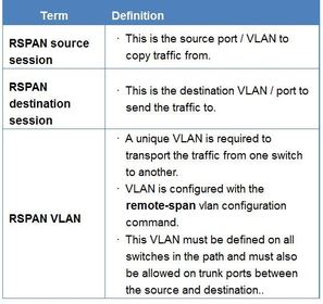
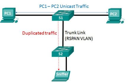
| Remote SPAN ** RSPAN allows source and destination ports to be in different switches. RSPAN is useful in campus networks where a packet analyzer is most likely not connected to the same switch on which you need to capture traffic | |
| Remote SPAN ** Remote SPAN uses two sessions, one session as the source and one session to copy or receive the traffic from a VLAN. Ej: Notice the trunk link used to carry the remote-span VLAN across the network. | |
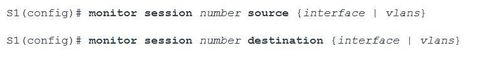
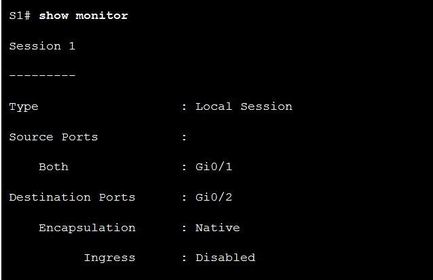
| Local SPAN Configuration Ej: ? commands to define the source port and destination ports for a SPAN session ** Note: The session ID used to define the source and destination ports must be the same in order to assign the ports to the same SPAN session. | |
| Local SPAN Configuration Ej: ? To verify the SPAN session configuration ** Note: The session ID used to define the source and destination ports must be the same in order to assign the ports to the same SPAN session. | |
| Troubleshooting with SPAN Overview Intrusion Protection Systems (IPSs) allows administrators to analyze the traffic and troubleshoot issues before sending the traffic on to the destination. As the traffic traverses the IPS, it is able to analyze traffic in real-time and take action upon the discovery of a pre-defined traffic pattern. IPSs are mainly used to detect network attacks as they happen, issuing alerts or even blocking the malicious packets as the attack takes place. | ** For example, a LAND (Local Area Network Denial) attack sends a spoofed TCP SYN packet (connection initiation) with the same source and destination IP address of the target host and the same source and destination port as an open port on the target. ** A LAND attack causes the machine to reply to itself continuously. Because only one packet is required to identify this type of attack, an IPS can easily prevent these packets from entering the network altogether. |
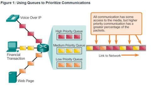
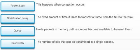
| Prioritizing Traffic Congestion occurs when the demand for bandwidth exceeds the amount available. When the volume of traffic is greater than what can be transported across the network, devices queue, or hold, the packets in memory until resources become available to transmit them ** Queuing packets causes delay because new packets cannot be transmitted until previous packets have been processed. If the number of packets to be queued continues to increase, the memory queues fill up and packets are dropped. | |
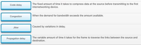
| Bandwidth, Congestion, Delay, and Jitter Network congestion causes delay. Variations in delay cause jitter. An interface experiences congestion when it is presented with more traffic than it can handle. ** Network congestion points are strong candidates for QoS mechanisms Note: A device only implements QoS when it is experiencing some type of congestion. | |
| Bandwidth, Congestion, Delay, and Jitter ** Jitter is the variation in the delay of received packets . At the sending side, packets are sent in a continuous stream with the packets spaced evenly apart. ** Due to network congestion, improper queuing, or configuration errors the delay between each packet can vary instead of remaining constant. Both delay and jitter need to be controlled and minimized to support real-time and interactive traffic. | |
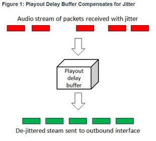
| Packet Loss When a router receives a Real-Time Protocol (RTP) digital audio stream for Voice over IP (VoIP), it must compensate for the jitter that is encountered. The mechanism that handles this function is the playout delay buffer. The playout delay buffer must buffer these packets and then play them out in a steady stream to be converted back to an analog audio stream ** For losses as small as one packet, the digital signal processor (DSP) interpolates what it thinks the audio should be and no problem is audible. However, when jitter exceeds what the DSP can do to make up for the missing packets, audio problems are heard. | |
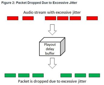
| Packet Loss Without any QoS mechanisms in place, packets are processed in the order in which they are received. When congestion occurs, routers and switches begin to drop packets. This means that time-sensitive packets, such as real-time video and voice, will be dropped with the same frequency as data that is not time-sensitive, such as email and web browsing. Ej: If the jitter is so large that it causes packets to be received out of the range of this buffer, the out-of-range packets are discarded and dropouts are heard in the audio | |
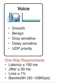
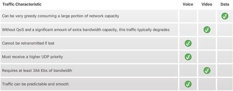
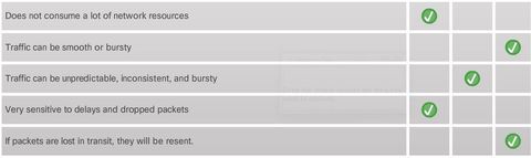
| Voice Traffic Characteristics Voice traffic is benign, meaning it does not consume a lot of network resources. However, voice is very sensitive to delays and dropped packets and it cannot be re-transmitted if lost. Therefore, it must receive a higher priority For example, Cisco products use the RTP port range 16384 to 32767 to prioritize voice traffic. | |
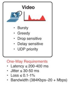
| Video Traffic Characteristics Video traffic tends to be unpredictable, inconsistent, and bursty compared to voice traffic. Compared to voice, video is less resilient to loss and has a higher volume of data per packet ** UDP ports, such as 554 used for the Real-Time Streaming Protocol (RSTP), should be given priority over other, less time-sensitive, network traffic | |
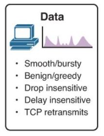
| Data Traffic Characteristics ** Some TCP applications can be very greedy, consuming a large portion of network capacity. FTP will consume as much bandwidth as it can get when you download a large file, such as a movie or game | |
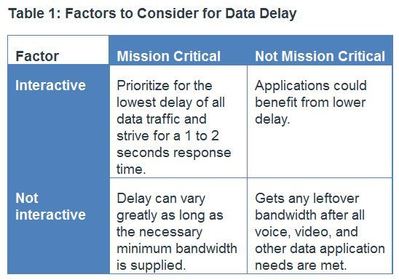
| Data Traffic Characteristics Although data traffic is relatively insensitive to drops and delays compared to voice and video, a network administrator still needs to consider the quality of the user experience, sometimes referred to as Quality of Experience or QoE. The two main factors a network administrator needs to ask about the flow of data traffic are the following: - Does the data come from an interactive application? - Is the data mission critical? | |
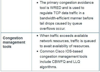
| Queuing ** The QoS policy implemented by the network administrator becomes active when congestion occurs on the link. Queuing is a congestion management tool that can buffer, prioritize, and, if required, reorder packets before being transmitted to the destination. A number of queuing algorithms are available: | For the purposes of this course, we will focus on the following: - First-In, First-Out (FIFO) - Weighted Fair Queuing (WFQ) - Class-Based Weighted Fair Queuing (CBWFQ) - Low Latency Queuing (LLQ) |
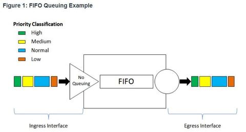
| First In First Out (FIFO) In its simplest form, FIFO queuing—also known as first-come, first-served (FCFS) queuing—involves buffering and forwarding of packets in the order of arrival. FIFO has no concept of priority or classes of traffic and consequently makes no decision about packet priority. There is only one queue, and all packets are treated equally. | |
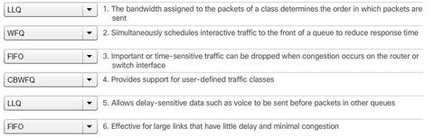
| First In First Out (FIFO) ** When FIFO is used, important or time-sensitive traffic can be dropped when congestion occurs on the router or switch interface. ** When no other queuing strategies are configured, all interfaces except serial interfaces at E1 (2.048 Mbps) and below use FIFO by default. (Serial interfaces at E1 and below use WFQ by default.) | ** FIFO, which is the fastest method of queuing, is effective for large links that have little delay and minimal congestion. If your link has very little congestion, FIFO queuing may be the only queuing you need to use. |
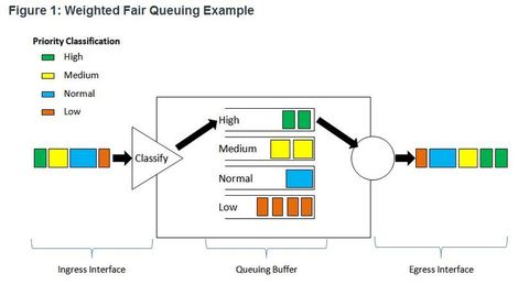
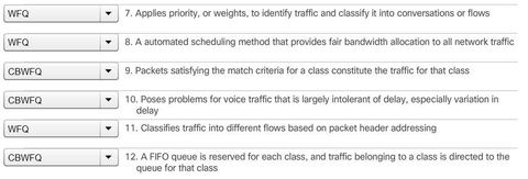
| Weighted Fair Queuing (WFQ) ** WFQ is an automated scheduling method that provides fair bandwidth allocation to all network traffic. WFQ applies priority, or weights, to identified traffic and classifies it into conversations or flows WFQ classifies traffic into different flows based on packet header addressing, including such characteristics as source and destination IP addresses, MAC addresses, port numbers, protocol, and Type of Service (ToS) value. The ToS value in the IP header can be used to classify traffic. | |
| Weighted Fair Queuing (WFQ) WFQ then determines how much bandwidth each flow is allowed relative to other flows. The flow-based algorithm used by WFQ simultaneously schedules interactive traffic to the front of a queue to reduce response time. It then fairly shares the remaining bandwidth among high-bandwidth flows. ** WFQ allows you to give low-volume, interactive traffic, such as Telnet sessions and voice, priority over high-volume traffic, such as FTP sessions. When multiple file transfers flows are occurring simultaneously, the transfers are given comparable bandwidth. | Limitations ** WFQ is not supported with tunneling and encryption because these features modify the packet content information required by WFQ for classification. ** Although WFQ automatically adapts to changing network traffic conditions, it does not offer the degree of precision control over bandwidth allocation that CBWFQ offers. |
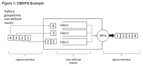
| Class-Based Weighted Fair Queuing (CBWFQ) ** CBWFQ extends the standard WFQ functionality to provide support for user-defined traffic classes. For CBWFQ, you define traffic classes based on match criteria including protocols, access control lists (ACLs), and input interfaces. Ej: packets satisfying the match criteria for a class constitute the traffic for that class. A FIFO queue is reserved for each class, and traffic belonging to a class is directed to the queue for that class | |
| Class-Based Weighted Fair Queuing (CBWFQ) ** When a class has been defined according to its match criteria, you can assign it characteristics. To characterize a class, you assign it bandwidth, weight, and maximum packet limit. The bandwidth assigned to a class is the guaranteed bandwidth delivered to the class during congestion. To characterize a class, you also specify the queue limit for that class, which is the maximum number of packets allowed to accumulate in the queue for the class. Packets belonging to a class are subject to the bandwidth and queue limits that characterize the class. | After a queue has reached its configured queue limit, adding more packets to the class causes tail drop or packet drop to take effect, depending on how class policy is configured. ** Tail drop means a router simply discards any packet that arrive at the tail end of a queue that has completely used up its packet-holding resources. This is the default queuing response to congestion. Tail drop treats all traffic equally and does not differentiate between classes of service. |
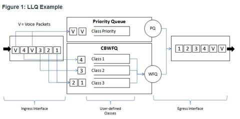
| Low Latency Queuing (LLQ) ** The LLQ feature brings strict priority queuing (PQ) to CBWFQ. Strict PQ allows delay-sensitive data such as voice to be sent before packets in other queues. LLQ provides strict priority queuing for CBWFQ, reducing jitter in voice conversations ** With LLQ, delay-sensitive data is sent first, before packets in other queues are treated. Although it is possible to enqueue various types of real-time traffic to the strict priority queue, Cisco recommends that only voice traffic be directed to it. | |
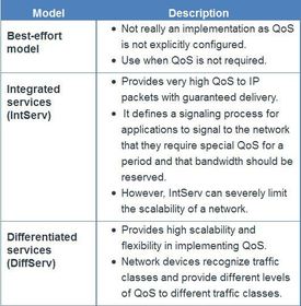
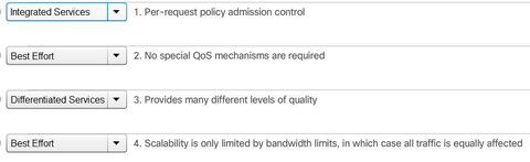
| Selecting an Appropriate QoS Policy Model ** QoS is really implemented in a network using either IntServ or DiffServ. While IntServ provides the highest guarantee of QoS, it is very resource-intensive and therefore limited in scalability. ** In contrast, DiffServ is less resource-intensive and more scalable. The two are sometimes co-deployed in network QoS implementations. Ej: There are three models for implementing QoS: | |
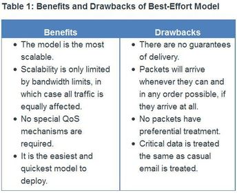
| Best-Effort This approach is still predominant on the Internet today and remains appropriate for most purposes. The best-effort model treats all network packets in the same way, so an emergency voice message is treated the same way a digital photograph attached to an email is treated. Without QoS, the network cannot tell the difference between packets and, as a result, cannot treat packets preferentially. | |
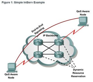
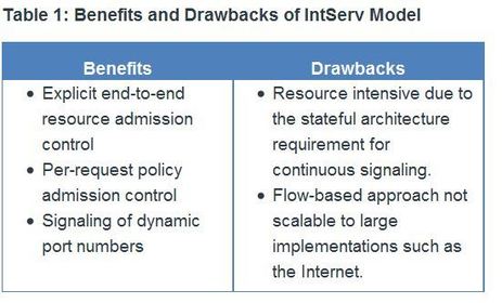
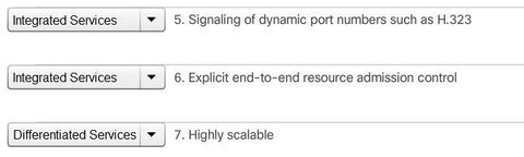
| Integrated Services IntServ provides a way to deliver the end-to-end QoS that real-time applications require by explicitly managing network resources to provide QoS to specific user packet streams, sometimes called microflows. It uses resource reservation and admission-control mechanisms as building blocks to establish and maintain QoS. ** This practice is similar to a concept known as “hard QoS.” Hard QoS guarantees traffic characteristics, such as bandwidth, delay, and packet-loss rates, from end to end. Hard QoS ensures both predictable and guaranteed service levels for mission-critical applications. | |
| Integrated Services ** IntServ uses a connection-oriented approach inherited from telephony network design. Each individual communication must explicitly specify its traffic descriptor and requested resources to the network. The edge router performs admission control to ensure that available resources are sufficient in the network. The IntServ standard assumes that routers along a path set and maintain the state for each individual communication. | The network performs admission control based on information from the application and available network resources. The network commits to meeting the QoS requirements of the application as long as the traffic remains within the profile specifications. The network fulfills its commitment by maintaining the per-flow state and then performing packet classification, policing, and intelligent queuing based on that state. |
| Integrated Services ** In the IntServ model, the application requests a specific kind of service from the network before sending data. The application informs the network of its traffic profile and requests a particular kind of service that can encompass its bandwidth and delay requirements. ** IntServ uses the Resource Reservation Protocol (RSVP) to signal the QoS needs of an application’s traffic along devices in the end-to-end path through the network. If network devices along the path can reserve the necessary bandwidth, the originating application can begin transmitting. If the requested reservation fails along the path, the originating application does not send any data. | |
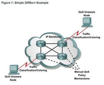
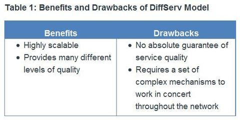
| Differentiated Services ** DiffServ is not an end-to-end QoS strategy because it cannot enforce end-to-end guarantees. However, DiffServ QoS is a more scalable approach to implementing QoS. Unlike IntServ and hard QoS in which the end-hosts signal their QoS needs to the network, DiffServ does not use signaling. Instead, DiffServ uses a “soft QoS” approach. It works on the provisioned-QoS model, where network elements are set up to service multiple classes of traffic each with varying QoS requirements. | |
| Differentiated Services ** As a host forwards traffic to a router, the router classifies the flows into aggregates (classes) and provides the appropriate QoS policy for the classes. DiffServ enforces and applies QoS mechanisms on a hop-by-hop basis, uniformly applying global meaning to each traffic class to provide both flexibility and scalability. For example, DiffServ groups all TCP flows as a single class, and allocates bandwidth for that class, rather than for the individual flows as IntServ would do. In addition to classifying traffic, DiffServ minimizes signaling and state maintenance requirements on each network node | ** Specifically, DiffServ divides network traffic into classes based on business requirements. Each of the classes can then be assigned a different level of service. As the packets traverse a network, each of the network devices identifies the packet class and services the packet according to that class. It is possible to choose many levels of service with DiffServ. For example, voice traffic from IP phones is usually given preferential treatment over all other application traffic, email is generally given best-effort service, and nonbusiness traffic can either be given very poor service or blocked entirely. |
| Differentiated Services ** The DiffServ design overcomes the limitations of both the best-effort and IntServ models. DiffServ can provide an “almost guaranteed” QoS while still being cost-effective and scalable. Note: Modern network primarily use the DiffServ model. However, due to the increasing volumes of delay- and jitter-sensitive traffic, IntServ and RSVP are sometimes co-deployed. | |
| Avoiding Packet Loss Packet loss is usually the result of congestion on an interface. Most applications that use TCP experience slowdown because TCP automatically adjusts to network congestion. Dropped TCP segments cause TCP sessions to reduce their window sizes. Some applications do not use TCP and cannot handle drops (fragile flows). The following approaches can prevent drops in sensitive applications: | * Increase link capacity to ease or prevent congestion. * Guarantee enough bandwidth and increase buffer space to accommodate bursts of traffic from fragile flows. Cisco IOS QoS software: WFQ, CBWFQ, and LLQ. ** Prevent congestion by dropping lower-priority packets before congestion occurs. Cisco IOS QoS provides queuing mechanisms that start dropping lower-priority packets before congestion occurs. An example being weighted random early detection (WRED). |
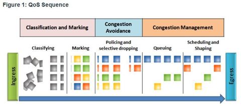
| QoS Tools Ej: ingress packets (gray squares) are classified and their respective IP header is marked (colored squares). To avoid congestion, packets are then allocated resources based on defined policies. Packets are then queued and forwarded out the egress interface based on their defined QoS shaping and policing policy. ** Note: Classification and marking can be done on ingress or egress, whereas other QoS actions such queuing and shaping are usually done on egress | |
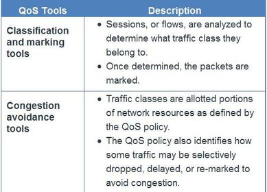
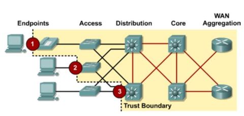
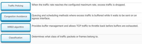
| Classification and Marking Before a packet can have a QoS policy applied to it, the packet has to be classified.Classification determines the class of traffic to which packets or frames belong. ** How a packet is classified depends on the QoS implementation. Methods of classifying traffic flows at Layer 2 and 3 include using interfaces, ACLs, and class maps. Traffic can also be classified at Layers 4 to 7 using Network Based Application Recognition (NBAR). | Note: NBAR is a classification and protocol discovery feature of Cisco IOS software that works with QoS features ** Marking means that we are adding a value to the packet header. Devices receiving the packet look at this field to see if it matches a defined policy. Marking should be done as close to the source device as possible. This establishes the trust boundary. |
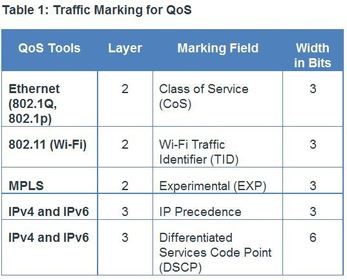
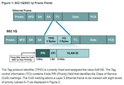
| Traffic Marking How traffic is marked usually depends on the technology. Ej: The decision of whether to mark traffic at Layers 2 or 3 or both is not trivial and should be made after consideration of the following three points: | 1. Layer 2 marking of frames can be performed for non-IP traffic. 2. Layer 2 marking of frames is the only QoS option available for switches that are not “IP aware” 3. Layer 3 marking will carry the QoS information end-to-end |
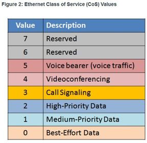
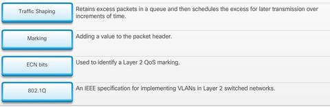
| Traffic Marking 802.1Q is the IEEE standard that supports VLANs on an Ethernet network. ** The standard also includes quality of service prioritization scheme known as IEEE 802.1p. | |
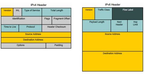
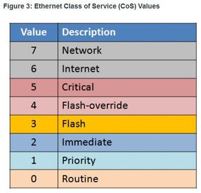
| Marking at Layer 3 Ej: IPv4 and IPv6 specify an 8-bit field in their packet headers to mark packets, the IPv4 has the “Type of Service” field and IPv6 has the “Traffic Class” 8-bit field. These fields are used to carry the packet marking as assigned by the QoS classification tools. The field is then referred to by receiving devices to forward the packets based on the appropriate assigned QoS policy. | |
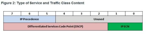
| Marking at Layer 3 Ej: displays the content of the 8-bit (i.e., 7 – 0) field. ** Note: The IP extended Congestion Notification (ECN) bits are used to identify a Layer 2 QoS marking. Examples include Ethernet 802.1p Class of Service (CoS) bits, the MAC bridge 802.1D user priority bits, or Multiprotocol Label Switching Experimental values (MPLS EXP). The first 3 significant left-hand high-order bits are referred to as the IP Precedence field. The 8 bits provides a total of eight possible classes of service | |
| Marking at Layer 3 Ej: The first 3 significant left-hand high-order bits are referred to as the IP Precedence field. The 8 bits provides a total of eight possible classes of service as displayed | |
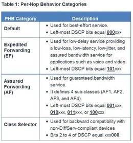
| Marking at Layer 3 When the DiffServ model is used, the packet is marked using 6-bits referred to as the DiffServ Code Point (DSCP) bits. Six bits offers a maximum of 64 possible classes of service. ** DiffServ-aware routers implement per-hop behaviors (PHBs), which define the packet forwarding properties associated with a class of traffic. Specifically, there are four categories of PBH as described in Table | |
| Trust Boundaries Traffic should be classified and marked as close to its source as technically and administratively feasible - Trusted endpoints have the capabilities and intelligence to mark application traffic to the appropriate Layer 2 CoS and/or Layer 3 DSCP values. Examples of trusted endpoints include IP phones, wireless access points, videoconferencing gateways and systems, IP conferencing stations, and more. - Secure endpoints can have traffic marked at the Layer 2 switch. - Traffic can also be marked at Layer 3 switches / routers. Re-marking of traffic is typically necessary. For example, re-marking CoS values to IP Precedent or DSCP values. | |
| Congestion Avoidance Congestion management includes queuing and scheduling methods where excess traffic is buffered or queued (and sometimes dropped) while it waits to be sent on an egress interface. Congestion avoidance tools are simpler. They monitor network traffic loads in an effort to anticipate and avoid congestion at common network and internetwork bottlenecks before congestion becomes a problem. Cisco IOS QoS includes weighted random early detection (WRED) as a possible congestion avoidance solution. | ** The WRED algorithm allows for congestion avoidance on network interfaces by providing buffer management and allowing TCP traffic to decrease, or throttle back, before buffers are exhausted. Using WRED helps avoid tail drops and maximizes network use and TCP-based application performance. ** There is no congestion avoidance for User Datagram Protocol (UDP)-based traffic, such as voice traffic. In case of UDP-based traffic, methods such as queuing and compression techniques help to reduce and even prevent UDP packet loss. |
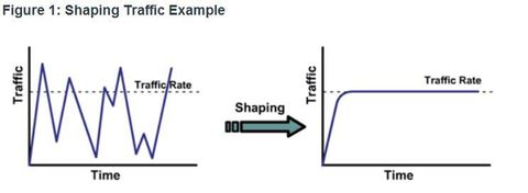
| Shaping and Policing Ej: Traffic shaping retains excess packets in a queue and then schedules the excess for later transmission over increments of time. The result of traffic shaping is a smoothed packet output rate Shaping implies the existence of a queue and of sufficient memory to buffer delayed packets, while policing does not. ** In addition, shaping requires a scheduling function for later transmission of any delayed packets. This scheduling function allows you to organize the shaping queue into different queues. Examples of scheduling functions are CBWFQ and LLQ. | |
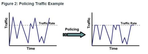
| Shaping and Policing Ej: In contrast, traffic policing propagates bursts. When the traffic rate reaches the configured maximum rate, excess traffic is dropped (or remarked). The result is an output rate that appears as a saw-tooth with crests and troughs ** Queuing is an outbound concept; packets going out an interface get queued and can be shaped. Only policing can be applied to inbound traffic on an interface. | |
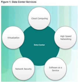
| Cloud Overview Cloud computing involves large numbers of computers connected through a network that can be physically located anywhere ** Providers rely heavily on virtualization to deliver their Cloud computing services. Cloud computing can reduce operational costs by using resources more efficiently. | ** Cloud computing, with its “pay-as-you-go” model, allows organizations to treat computing and storage expenses more as a utility rather than investing in infrastructure. Capital expenditures are transformed into operating expenditures. |
| Cloud Overview Cloud computing supports a variety of data management issues: | * Enables access to organizational data anywhere and at any time * Streamlines the organization’s IT operations by subscribing only to needed services * Eliminates or reduces the need for onsite IT equipment, maintenance, and management * Reduces cost for equipment, energy, physical plant requirements, and personnel training needs * Enables rapid responses to increasing data volume requirements |
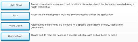
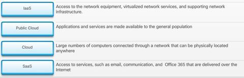
| Cloud Services The three main Cloud computing services defined by the National Institute of Standards and Technology (NIST) in their Special Publication 800-145 are as follows: 1. Software as a Service (SaaS): The Cloud provider is responsible for access to services, such as email, communication, and Office 365 that are delivered over the Internet. The user is only needs to provide their data. | 2. Platform as a Service (PaaS): The Cloud provider is responsible for access to the development tools and services used to deliver the applications. 3. Infrastructure as a Service (IaaS): The Cloud provider is responsible for access to the network equipment, virtualized network services, and supporting network infrastructure. Cloud service providers have extended this model to also provide IT support for each of the Cloud computing services (ITaaS). |
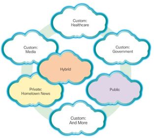
| Cloud Models 1. Public clouds: Cloud-based applications and services offered in a public cloud are made available to the general population. Services may be free or are offered on a pay-per-use model, such as paying for online storage. The public cloud uses the Internet to provide services. 2. Private clouds: Cloud-based applications and services offered in a private cloud are intended for a specific organization or entity, such as the government. A private cloud can be set up using the organization’s private network, though this can be expensive to build and maintain. A private cloud can also be managed by an outside organization with strict access security. | |
| Cloud Models 3. Hybrid clouds: A hybrid cloud is made up of two or more clouds (example: part custom, part public), where each part remains a distinctive object, but both are connected using a single architecture. Individuals on a hybrid cloud would be able to have degrees of access to various services based on user access rights. 4. Custom clouds: These are clouds built to meet the needs of a specific industry, such as healthcare or media. Custom clouds can be private or public | |
| Cloud Computing versus Data Center - Data center: Typically a data storage and processing facility run by an in-house IT department or leased offsite. - Cloud computing: Typically an off-premise service that offers on-demand access to a shared pool of configurable computing resources. These resources can be rapidly provisioned and released with minimal management effort. Ej: Cloud computing is often a service provided by data centers | |
| Cloud Computing and Virtualization Virtualization is the foundation of Cloud computing. Without it, Cloud computing, as it is most-widely implemented, would not be possible. ** Cloud computing separates the application from the hardware. Virtualization separates the OS from the hardware | Various providers offer virtual Cloud services that can dynamically provision servers as required. For example, Amazon Elastic Compute Cloud (Amazon EC2) web service provides a simple way for customers to dynamically provision the compute resources they need. These virtualized instances of servers are created on demand in Amazon’s EC2. |
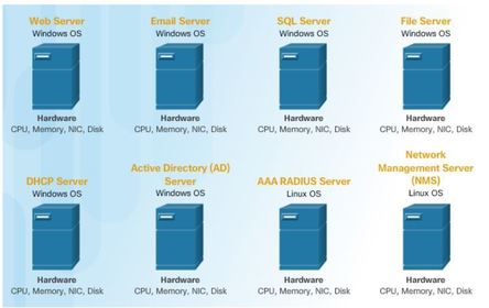
| Dedicated Servers The major problem with this configuration is that when a component fails, the service that is provided by this server becomes unavailable. This is known as a single point of failure. Another problem was that dedicated servers were underused.Dedicated servers often sat idle for long periods of time, waiting until there was a need to deliver the specific service they provide. These servers wasted energy and took up more space than was warranted by their amount of service. This is known as server sprawl. | |
| Server Virtualization Server virtualization takes advantage of idle resources and consolidates the number of required servers. This also allows for multiple operating systems to exist on a single hardware platform. ** The hypervisor is a program, firmware, or hardware that adds an abstraction layer on top of the real physical hardware. The abstraction layer is used to create virtual machines which have access to all the hardware of the physical machine such as CPUs, memory, disk controllers, and NICs | |
| Server Virtualization The use of virtualization normally includes redundancy to protect from a single point of failure. Redundancy can be implemented in different ways. ** If the hypervisor fails, the VM can be restarted on another hypervisor. Also, the same VM can be run on two hypervisors concurrently, copying the RAM and CPU instructions between them. If one hypervisor fails, the VM continues running on the other hypervisor. The services running on the VMs are also virtual and can be dynamically installed or uninstalled, as needed. | The hypervisor is a program, firmware, or hardware that adds an abstraction layer on top of the real physical hardware. The abstraction layer is used to create virtual machines which have access to all the hardware of the physical machine such as CPUs, memory, disk controllers, and NICs Each of these virtual machines runs a complete and separate operating system. With virtualization, enterprises can now consolidate the number of servers. For example, it is not uncommon for 100 physical servers to be consolidated as virtual machines on top of 10 physical servers using hypervisors. |
| Advantages of Virtualization One major advantage of virtualization is overall reduced cost: 1. Less equipment is required - Virtualization enables server consolidation, which requires fewer physical servers, fewer networking devices, and less supporting infrastructure. It also means lower maintenance costs. | 2. Less energy is consumed - Consolidating servers lowers the monthly power and cooling costs. Reduced consumption helps enterprises to achieve a smaller carbon footprint. 3. Less space is required - Server consolidation with virtualization reduces the overall footprint of the data center. Fewer servers, network devices, and racks reduce the amount of required floor space. |
| These are additional benefits of virtualization: * Faster server provisioning - Creating a virtual server is far faster than provisioning a physical server. * Increased server uptime - Most server virtualization platforms now offer advanced redundant fault tolerance features, such as live migration, storage migration, high availability, and distributed resource scheduling. They also support the ability to move a virtual machine from one server to another. * Legacy Support - Virtualization can extend the life of OSs and applications providing more time for organizations to migrate to newer solutions | * Easier prototyping - Self-contained labs, operating on isolated networks, can be rapidly created for testing and prototyping network deployments. If a mistake is made, an administrator can simply revert to a previous version. The testing environments can be online, but isolated from end users. When testing is completed, the servers and systems can be deployed. * Improved disaster recovery - Virtualization offers advanced business continuity solutions. It provides hardware abstraction capability so that the recovery site no longer needs to have hardware that is identical to the hardware in the production environment. Most enterprise server virtualization platforms also have software that can help test and automate the failover before a disaster does happen. |
| Abstraction Layers To help explain how virtualization works, it is useful to use layers of abstraction in computer architectures. Ej: ? A computer system consists of the following abstraction layers: | |
| Abstraction Layers At each of these layers of abstraction, some type of programming code is used as an interface between the layer below and the layer above. For example, the programming language C is often used to program the firmware that accesses the hardware. Ej: A hypervisor is installed between the firmware and the OS. The hypervisor can support multiple instances of OSs. | |
| Type 2 Hypervisors A hypervisor is software that creates and runs VM instances. The computer, on which a hypervisor is supporting one or more VMs, is a host machine. Type 2 hypervisors are also called hosted hypervisors. This is because the hypervisor is installed on the existing OSThen, one or more additional OS instances are installed on the hypervisor A big advantage of Type 2 hypervisors is that management console software is not required. | |
| Type 1 Hypervisors Type 1 hypervisors are also called the “bare metal” approach because the hypervisor is installed directly on the hardware. ** Type 1 hypervisors have direct access to the hardware resources; therefore, they are more efficient than hosted architectures. Type 1 hypervisors improve scalability, performance, and robustness. | |
| Installing a VM on a Hypervisor When a Type 1 hypervisor is installed, and the server is rebooted, only basic information is displayed, such as the OS version, the amount of RAM, and the IP address. An OS instance cannot be created from this screen. ** Type 1 hypervisors require a “management console” to manage the hypervisor. Management software is used to manage multiple servers using the same hypervisor. The management console can automatically consolidate servers and power on or off servers as required. | ** Some management consoles also allow over allocation. Over allocation is when multiple OS instances are installed, but their memory allocation exceeds the total amount of memory that a server has. For example, a server has 16 GB of RAM, but the administrator creates four OS instances with 10 GB of RAM allocated to each. This type of over allocation is a common practice because all four OS instances rarely require the full 10 GB of RAM at any one moment. |
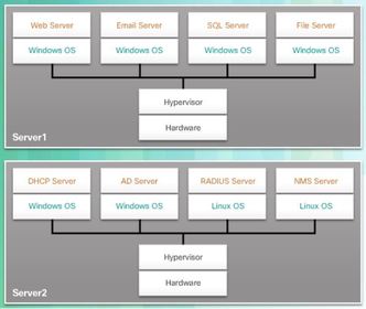
| Installing a VM on a Hypervisor Ej: assume that Server1 in Figure becomes low on resources. To make more resources available, the management console moves the Windows instance to the hypervisor on Server2. ** The management console provides recovery from hardware failure. If a server component fails, the management console automatically and seamlessly moves the VM to another server. | |
| Network Virtualization Server virtualization hides server resources (for example, the number and identity of physical servers, processors, and OSs) from server users. This practice can create problems if the data center is using traditional network architectures. For example, Virtual LANs (VLANs) used by VMs must be assigned to the same switch port as the physical server running the hypervisor. However, VMs are movable, and the network administrator must be able to add, drop, and change network resources and profiles. This process is difficult to do with traditional network switches. Another problem is that traffic flows differ substantially from the traditional client-server model. Typically, a data center has a considerable amount of traffic being exchanged between virtual servers (referred to as East-West traffic). | These flows change in location and intensity over time, requiring a flexible approach to network resource management. Existing network infrastructures can respond to changing requirements related to the management of traffic flows by using Quality of Service (QoS) and security level configurations for individual flows. However, in large enterprises using multivendor equipment, each time a new VM is enabled, the necessary reconfiguration can be very time-consuming. Could the network infrastructure also benefit from virtualization? If so, then how? The answer is found in how a networking device operates using a data plane and a control plane. |
| Control Plane and Data Plane 1. Control plane - This is typically regarded as the brains of a device. It is used to make forwarding decisions. The control plane contains ** Layer 2 and Layer 3 route forwarding mechanisms, such as routing protocol neighbor tables and topology tables, IPv4 and IPv6 routing tables, STP, and the ARP table. Information sent to the control plane is processed by the CPU. | 2. Data plane - Also called the forwarding plane, this plane is typically the switch fabric connecting the various network ports on a device. The data plane of each device is used to forward traffic flows. ** Routers and switches use information from the control plane to forward incoming traffic out the appropriate egress interface. Information in the data plane is typically processed by a special data plane processor, such as a digital signal processor (DSP), without the CPU getting involved. |
| Control Plane and Data Plane ** CEF is an advanced, Layer 3 IP switching technology that enables forwarding of packets to occur at the data plane without consulting the control plane. In CEF, the control plane’s routing table pre-populates the CEF Forwarding Information Base (FIB) table in the data plane. ** The control plane’s ARP table pre-populates the Adjacency table. Packets are then forwarded directly by the data plane based on the information contained in the FIB and Adjacency table, without the need to consult the information in the control plane. | |
| Control Plane and Data Plane ** To virtualize the network, the control plane function is removed from each device and is performed by a centralized controller The centralized controller communicates control plane functions to each device. Each device can now focus on forwarding data while the centralized controller manages data flow, increases security, and provides other services. | |
| Network Virtualization Two major network architectures have been developed to support network virtualization: - Software Defined Networking (SDN) - A network architecture that virtualizes the network. - Cisco Application Centric Infrastructure (ACI) - A purpose-built hardware solution for integrating Cloud computing and data center management. | Over a decade ago, VMware developed a virtualizing technology that enabled a host OS to support one or more client OSs. Most virtualization technologies are now based on this technology. The transformation of dedicated servers to virtualized servers has been embraced and is rapidly being implemented in data center and enterprise networks |
| Network Virtualization These are some other network virtualization technologies, some of which are included as components in SDN and ACI: - OpenFlow - This approach was developed at Stanford University to manage traffic between routers, switches, wireless access points, and a controller. The OpenFlow protocol is a basic element in building SDN solutions. - OpenStack - This approach is a virtualization and orchestration platform available to build scalable Cloud environments and provide an infrastructure as a service (IaaS) solution. OpenStack is often used with Cisco ACI. | Orchestration in networking is the process of automating the provisioning of network components such as servers, storage, switches, routers, and applications. - Other components - Other components include Interface to the Routing System (I2RS), Transparent Interconnection of Lots of Links (TRILL), Cisco FabricPath (FP), and IEEE 802.1aq Shortest Path Bridging (SPB). |
| SDN Architecture Software defined networking (SDN) is a network architecture that has been developed to virtualize the network. For example, SDN can virtualize the control plane. Also known as controller-based SDN, SDN moves the control plane from each network device to a central network intelligence and policy-making entity called the SDN controller. ** The SDN controller is a logical entity that enables network administrators to manage and dictate how the data plane of virtual switches and routers should handle network traffic. It orchestrates, mediates, and facilitates communication between applications and network elements. | |
| SDN Architecture Ej: Note the use of Application Programming Interfaces (APIs) within the SDN framework. An API is a set of standardized requests that define the proper way for an application to request services from another application. The SDN controller uses northbound APIs to communicate with the upstream applications. ** These APIs help network administrators shape traffic and deploy services. The SDN controller also uses southbound APIs to define the behavior of the downstream virtual switches and routers. OpenFlow is the original and widely implemented southbound API. Note: Traffic in a modern data center is described as North-South (going between external data center users and the data center servers) and East-West (going between data center servers). | |
| SDN Controller and Operations ** The SDN controller defines the data flows that occur in the SDN Data Plane. A flow is a sequence of packets traversing a network that share a set of header field values. For example, a flow could consist of all packets with the same source and destination IP addresses, or all packets with the same VLAN identifier. | ** Each flow through the network must first get permission from the SDN controller, which verifies that the communication is permissible according to the network policy. If the controller allows a flow, it computes a route for the flow to take and adds an entry for that flow in each of the switches along the path. |
| SDN Controller and Operations All complex functions are performed by the controller. The controller populates flow tables and switches manage the flow tables Ej: an SDN controller communicates with OpenFlow-compatible switches using the OpenFlow protocol. This protocol uses Transport Layer Security (TLS) to securely send control plane communications over the network. Each OpenFlow switch connects to other OpenFlow switches. They can also connect to end-user devices that are part of a packet flow. | |
| SDN Controller and Operations Within each switch, a series of tables implemented in hardware or firmware are used to manage the flows of packets through the switch. To the switch, a flow is a sequence of packets that matches a specific entry in a flow table. The tables serve the following purposes: * Flow Table - This matches incoming packets to a particular flow and specifies the functions that are to be performed on the packets. There may be multiple flow tables that operate in a pipeline fashion. * Meter Table - This triggers a variety of performance-related actions on a flow. A flow table may direct a flow to a Group Table, which may trigger a variety of actions that affect one or more flows. | |
| Core Components of ACI 1. Application Network Profile (ANP) - An ANP is a collection of end-point groups (EPG), their connections, and the policies that define those connections. The EPGs shown in Figure 1, such as VLANs, Web Services, and Applications, are just examples. An ANP is often much more complex. 2. Application Policy Infrastructure Controller (APIC) – is considered to be the brains of the ACI architecture. APIC is a centralized software controller that manages and operates a scalable ACI clustered fabric. It is designed for programmability and centralized management. It translates application policies into network programming. | |
| Core Components of ACI 3. Cisco Nexus 9000 Series switches – These switches provide an application-aware switching fabric and work with an APIC to manage the virtual and physical network infrastructure. The APIC translates the application requirements into a network configuration to meet those needs. | |
| Spine-Leaf Topology The Cisco ACI fabric is composed of the APIC and the Cisco Nexus 9000 series switches using two-tier spine-leaf topology ** The leaf switches always attach to the spines, but they never attach to each other. Similarly, the spine switches only attach to the leaf and core switches (not shown). In this two-tier topology, everything is one hop from everything else. The Cisco APICs and all other devices in the network physically attach to leaf switches | |
| Spine-Leaf Topology ** When compared to SDN, the APIC controller does not manipulate the data path directly. Instead, the APIC centralizes the policy definition and programs the leaf switches to forward traffic based on the defined policies. For virtualization, ACI supports multivendor hypervisor environments that would connect to the leaf switches, including the following: Microsoft (Hyper-V/SCVMM/Azure Pack) Red Hat Enterprise Linux OS (KVM OVS/OpenStack) VMware (ESX/vCenter/vShield) | |
| SDN Types 1. Device-based SDN - In this type of SDN, the devices are programmable by applications running on the device itself or on a server in the network Cisco OnePK is an example of a device-based SDN. It enables programmers to build applications using C, and Java with Python, to integrate and interact with Cisco devices. | |
| SDN Types 2. Controller-based SDN - This type of SDN uses a centralized controller that has knowledge of all devices in the network The applications can interface with the controller responsible for managing devices and manipulating traffic flows throughout the network. The Cisco Open SDN Controller is a commercial distribution of OpenDaylight. | |
| SDN Types 3. Policy-based SDN - This type of SDN is similar to controller-based SDN where a centralized controller has a view of all devices in the network Policy-based SDN includes an additional Policy layer that operates at a higher level of abstraction. It uses built-in applications that automate advanced configuration tasks via a guided workflow and user-friendly GUI with no programming skills required. Cisco ** The Cisco Application Policy Infrastructure Controller - Enterprise Module (APIC-EM) extends ACI aimed at enterprise and campus deployments and is an example of this type of SDN. | |
| APIC-EM Features Policy-based SDN is the most robust, providing for a simple mechanism to control and manage policies across the entire network. Cisco APIC-EM provides the following features: 1, Discovery - Supports a discovery functionality that is used to populate the controller's device and host inventory database. 2. Device Inventory - Collects detailed information from devices within the network including device name, device status, MAC address, IPv4/IPv6 addresses, IOS/Firmware, platform, up time, and configuration. | 3. Policy - Ability to view and control policies across the entire network including QoS. 4. Policy Analysis - Inspection and analysis of network access control policies. Ability to trace application specific paths between end devices to quickly identify ACLs in use and problem areas. Enables ACL change management with easy identification of redundancy, conflicts and incorrect ordering of access control entries. Incorrect ACL entries are known as shadows. |
| APIC-EM Features 5. Host Inventory - Collects detailed information from hosts with the network including host name, user ID, MAC address, IPv4/IPv6 addresses, and network attachment point. 6. Topology - Supports a graphical view of the network (topology view). The Cisco APIC-EM automatically discovers and maps devices to a physical topology with detailed device level data. Ej: In addition, auto-visualization of Layer 2 and 3 topologies on top of the physical topology provides a granular view for design planning and simplified troubleshooting. | |
| APIC-EM ACL Analysis One of the most important features of the APIC-EM controller is the ability to manage policies across the entire network. ** Policies operate at a higher level of abstraction. Traditional device configuration applies to one device at a time, whereas SDN policies apply to the entire network. | APIC-EM ACL Analysis and Path Trace provide tools to allow the administrator to analyze and understand ACL policies and configurations. Creating new ACLs or editing existing ACLs across a network to implement a new security policy can be challenging. Administrators are hesitant of changing ACLs for fear of breaking them and causing new problems. ACL Analysis and Path Trace allows the administrator to easily visualize traffic flows and discover any conflicting, duplicate, or shadowed ACL entries. |
| APIC-EM ACL Analysis APIC-EM provides the following tools to troubleshoot ACL entries: 1. ACL Analysis This tool examines ACLs on devices, searching for redundant, conflicting, or shadowed entries. ACL Analysis enables ACL inspection and interrogation across the entire network, exposing any problems and conflicts | |
| APIC-EM ACL Analysis APIC-EM provides the following tools to troubleshoot ACL entries: 2. ACL Path Trace This tool examines specific ACLs on the path between two end nodes, displaying any potential issues. | |
| IP Service Level Agreements (SLAs) are a feature of the Cisco IOS that allows the analysis of IP service levels. IP SLAs use generated traffic to measure network performance between two networking devices, multiple network locations, or across multiple network paths. Network engineers use IP SLAs to simulate network data and IP services to collect network performance information in real time. Performance monitoring can be done anytime, anywhere, without deploying a physical probe. | Note: Ping and Traceroute are probe tools. A physical probe is different. It is a device that can be inserted somewhere in the network to collect and monitor traffic. The use of physical probes is beyond the scope of this course. ** Multiple IP SLAs operations can be running on the network or on a device at any time. IP SLAs can be accessed by using either the Command Line Interface (CLI) or through Simple Network Management Protocol (SNMP). |
| IP Service Level Agreements (SLAs) Measurements provided by the various IP SLA operations can be used for troubleshooting network operation by providing consistent, reliable measurements that immediately identify problems and save troubleshooting time. Ej: ? Additional benefits for using IP SLAs are listed below: | * Service-level agreement monitoring, measurement, and verification * Network performance monitoring: - Measures the jitter, latency, or packet loss in the network - Provides continuous, reliable, and predictable measurements * IP service network health assessment to verify that the existing QoS is sufficient for new IP services * Edge-to-edge network availability monitoring for proactive connectivity verification of network resources |
| IP SLA Configuration Using IP SLAs for Troubleshooting Instead of using ping manually, a network engineer can use the IP SLA ICMP Echo operation to test the availability of network devices. A network device can be any device with IP capabilities (router, switch, PC, server, etc.). Ej: ? The IP SLA ICMP Echo operation provides the following measurements: | * Availability monitoring (packet loss statistics) * Performance monitoring (latency and response time) * Network operation (end-to-end connectivity) |
| Verifying that the IP SLA ICMP Echo Operation is Available Ej: ? command in privileged EXEC mode to verify that the desired IP SLA operation is available on the source device. | |
| Configure the IP SLA ICMP Echo Operation Ej: - The ip sla schedule command is scheduling the IP SLA operation-number 1 to start immediately (now) and continue until manually cancelled (forever). Note: Use the no ip sla schedule (operation-number) command to cancel the SLA operation. The SLA operation configuration is preserved and can be rescheduled when needed. | |
| Verifying IP SLA Configuration Ej: ? command to display configuration values including all defaults for IP SLA operations or for a specific operation | |
| Displaying IP SLAs Operation Statistics Ej: ? command to display the IP SLA operation monitoring statistics The example shows that the last ping to R3’s S1 interface has a 12 milliseconds round-trip time. Since the operation was started, it has tested connectivity 57 times with no failures. |
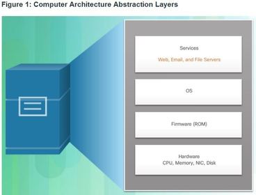
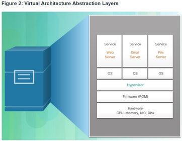
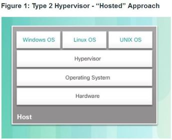
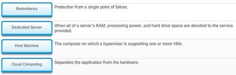
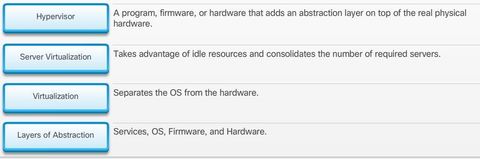
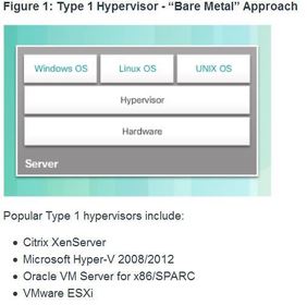
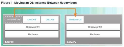
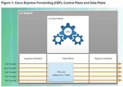
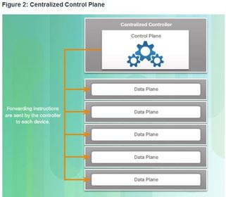
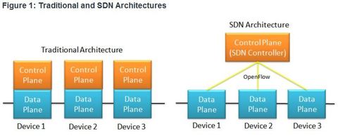
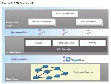
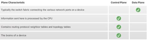
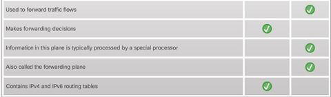
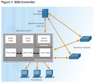
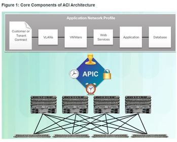
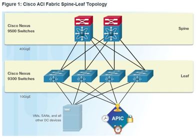
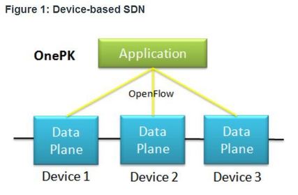
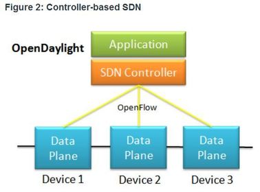
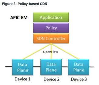
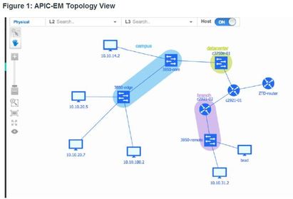
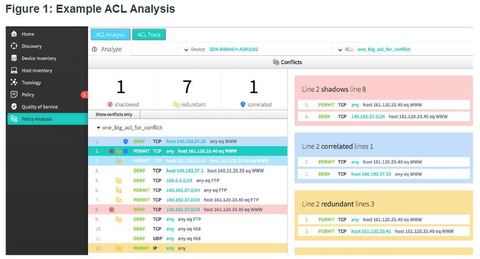
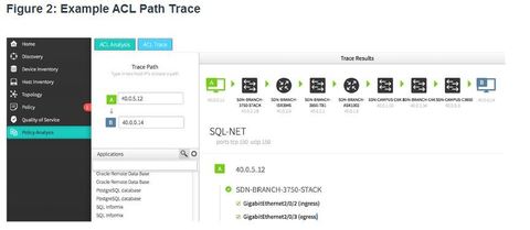
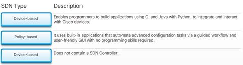
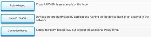
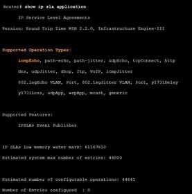
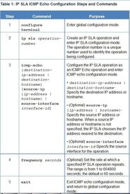
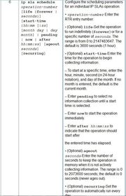
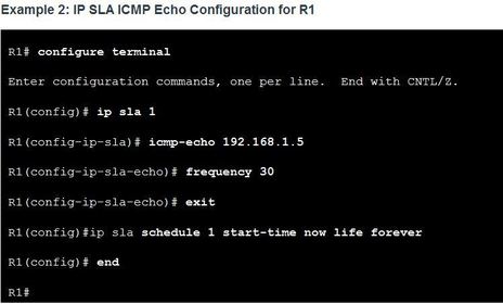
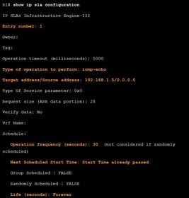
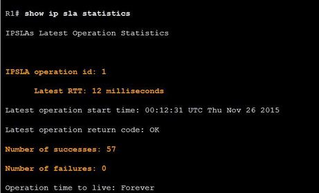
Want to create your own Flashcards for free with GoConqr? Learn more.