1815840
Description
Flashcards by Chima Power, updated more than 1 year ago
|
|
Created by Chima Power
over 9 years ago
|
|
| Question | Answer |
| X-Rays | These are electromagnetic waves at short wavelength end of the electromagnetic spectrum. Their produced in an x-ray tube when fast moving electrons hit a target. Their wavelength are about the same as the diameter of an atom. |
| Radiograph | To make this or an x-ray photograph x-rays from an x-ray tube are directed at the patient. A lightproof cassette containing a photographic film or a flat panel detector. When the x-ray tube is switched on x-rays from the tube pass through the part of patients body under investigation. X-rays pass through soft tissue but are absorbed by bones, teeth and metal objects with a greater density. Parts of the detector that x-ray reaches become darker so bones appear lighter than surrounding tissue that appears dark. The radio graph shows a negative image of the bones, a hole or cavity in a tooth shows up dark in comparison to the bright tooth. An organ consisting of soft tissue requires a contrast medium that absorb x-rays easily so that the internal surfaces in the organ to be seen on the radiograph. For instance to obtain the radio graph of a stomach the patient is given a barium meal which absorbs x-rays. Lead absorber plates between the tube and the patient stop x-rays reaching other parts of the body used as it's a good absorber of x-rays, those reaching patient pass through gap. |
| Flat panel detector | This is a small screen containing a CCD (charge coupled device), the sensors in the CCD are covered by a layer of a substance that converts x-rays to light. The light rays then create electronic signals in the sensor that are sent to computer which displays the x-ray image digitally. |
| X-Ray Safety | Such radiation dangerous as has great ionising effect on substances that it passes through, high doses kill living cells. However low doses cause cell mutation and cancerous growth. There's no evidence of a safe limit below living cells will not be damaged. Worker who use equipment or substances that produce x-radiation must wear a film badge. If the badge is overexposed to such radiation its wearer is stopped from working with the equipment. |
| X-ray therapy | Doctors use x-ray therapy to destroy cancerous tumours in our body, thick plates between the x-ray tube and the body stop x-ray stop the x-rays reaching healthy parts of the body. A gap between the plates allow the x-rays to reach the tumour. X-rays for therapy have shorter wavelengths than those used for imaging. |
| CT scanner | Stands for computerised tomography scanner and produces a digital image of any cross section in the body. It can also be used to construct a 3-D image of an organ. X-ray tube moves around the inside of the ring in the small steps automatically. At each position x-rays from the tube pass through the patient and reach the detector ring. Electronic signals from the detector are recorded by a computer until the tube has moved around the ring. Computer displays a digital image of the scanned area. Detector signal depends on the different types of tissue along the x-ray path and how far the x-ray pass through each type of tissue. |
| Ultrasound | Human ear can detect sound waves in frequency range of 20Hz to 20,000Hz, sound waves above the highest frequency that humans can detect are called ultrasounds. |
| Ultrasound scanners Check this bit with textbook. | Ultrasound waves are used for prenatal scans of a baby in the womb. Also used to map organs in the body such as kidney or damaged ligements. Ultrasound waves sent to the organ, this is partially reflected from the different tissue boundaries in the path, returns to the transducer as a sequence of reflected pulse from the boundaries arriving back at different times. Transducer is moved across the surface of the body over different parts the pulse is then detected by the transducer, they are used to build up an image on a screen of the internal tissue boundaries in the body. Advantages of ultrasound is there not ionising therefore harmless when scanning, reflected at boundaries between different types of tissue so can be used to map soft tissue. |
| Distance measurments | This can be used sometimes to restore sight to a blind person by replacing the eye lens with artificial lens. Before this is done the eye surgeon needs to know how long the eyeball is in order to give clear vision. In this case an ultrasound is used to measure the length of the eyeball such a scan is an A-scan. An oscilloscope can be used to measure the transit time of each pulse. Which is the time taken by the pulse to travel from the transmitter to and from the boundary that reflected it. Can calculate distance using s=v*t or displacement(m)= velocity (m/s) * time(seconds) (Too easy!). Since it travels to the boundary and back depth of boundary is half the distance travelled by each pulse so: depth of boundary below the surface= 0.5*speed of ultrasound*transit time |
| Ultrasound therapy | Powerful ultrasounds can break kidney stones which can be very painful into smaller bits, fragments which are small enough to naturally leave the kidney. Transmitter is used in an A-scan system so the waves are aimed directly at the kidney stone. |
| Refractive index | When light travels from air into a transparent substance its direction may change say refraction of light takes place at the boundary between air and transparent substance. In such a case if light source is directed at a right angle along the normal perpendicular to the transparent substance then no refraction occurs. For an light ray travelling through a more dense transparent substance the angle of refraction will be smaller than the angle of index and the greater the angle of index the larger the angle of refraction. |
| Snell's law | Sin of the index angle divided by sin of the refractive angle are always equal regardless of angle of index. This was first discover in 1816 and has since been called Snell's law. |
| Law of refraction | For a light travelling form air into an transparent substance the ratio of sin i/sin r is always the same for the same substance. This ratio is called the refractive index. So the radioactive index of a substance(n) = sin i / sin r. Can be arranged to attain sin i or sin r if have radioactive index :) When a light travels from a transparent substance into air at a non zero angle of incidence: the light ray is refracted away from the normal and the larger the angle of index the larger the angle of refraction sine of angle in the air = n * sine of the angle in glass |
| Endoscope | Involves use of optical fibres which are very thin glass fibres designed to transmit light or infrared radiation. Used in medicine to see inside the body without cutting the body and used in telecommunications to are used to send secure signals. The light rays are unable to escape from the fibre each light ray entering a fibre at one end and leaving the fibre at the other end even if its bends around. As light rays in the fibre is totally internally reflected each time it reaches the fibre's boundary. |
| Total internal reflection | Light rays travelling from glass into air at non zero angle of incidence is refracted away from the normal. Angle of reflection of this ray in the glass is the same as the angle of incidence. If the angle of incidence is gradually increasing the angle of refraction increases until the refracted ray emerges along the boundary. The angle of incidence at this position is referred to as critical angle. If the angle of incidence is increased beyond the critical angle the light ray is totally internally reflected. When this happens the angle of incidence is equal to the angle of refraction. |
| Total internal reflection calculation | the sine of the angle in air = n * sine of the angle in the transparent substance This can be applied to critical angle ray as act perpendicular to normal. Such that Sin90= n * Sin c as Sin 90=1 1= n * Sin c which can be rearranged to find n or c Example: Calculate the critical |
| Endoscope | this is used by a surgeon to see inside a body cavity such as the stomach without cutting the body open. Inserted into the stomach through patients throat, it contains two bundles of optical fibres alongside each other, one used to shine light of the cavity and the other to see the internal structure of the cavity. A tiny lense on one end of the second bundle is used to form an image that can be sent directly or through a digital camera. For example the endoscope |
| Endoscope: Laser light | This can be used as a source of energy in an endoscope in order to carry out some surgical procedures. It can be used to cut, or burn away and destroy diseased tissue. Also it can cauterise (seal off) leaky blood vessels as laser light energy can be focused on a very small area. Plus the laser light colour can be matched to the colour of the tissue by choosing the appropriate light source the absorption is more effective. Eye surgery on the retina by applying the laser light through the pupil of the eye for a short duration of time. Safety was be taken into factor a laser should be never be looked at our long even if reflected as can cause permanent damage to the retina causing blindness, special safety googles should be worn. |
| Lenses | Used in optical devices like camera's, they work by changing the direction of light passing through it. The curved surface of lens refracts the light so that it meets a point. Converging (convex) lens makes parallel lenses converge to a focus. The point at which the parallel rays are focused is called the principal focus. These are use in magnifying lenses and in optical camera's to form a clear image of distant objects. Diverging (concave) lens make parallel lenses diverge. The point at which the rays appear to come from is the principal focus these are used to correct short sight. The distance from the centre of the lens to the principal focus is the focal length of the lens. This is usually drawn on a ray diagram on both sides of the lens. |
| Real image | If the object is at different distances beyond the principal focus of the lens then the position of the lens can be adjusted until a clear object of the image is identified this is the real image. This is formed on the screen where the light rays meet. When the object is far away the real image is formed at the principal focus. As the rays from any point are effectively parallel to each other when they reach the lens. If the object is moved nearer the lens towards its principal focus the screen must be moved further from the lens to see the real image. The nearer the object to the lens the larger the image. With the image closer to the lens than the principal focus a magnified image is formed, this is a virtual image as its formed where the rays appear to come from. This image can only be seen when you look into the lens from the side opposite of the lens, duh! In this situation the lens act as a magnifying glass. |
| Magnification | The magnification produced by lens= image height/ object height If the virtual image is larger than the object the magnification is above 1 if the virtual image is smaller than the object the magnification is less than one. |
| Position and nature of image formed by lens | This depends on the focal length of the lens and the distance from the object to the lens. If this is known the position and nature of the image by drawing a ray diagram. |
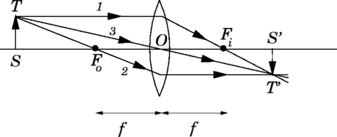
| Formation of a real image by converging lens | To form a real image using a converging (convex) lens object must be beyond the principal focus of lens. Image is formed on the other side of the lens to the object. Diagram shows we can use three 'key' construction lines from single point of the object to locate the image. - Principal axis of the lens is straight line that passes along the normal at the centre of each lens surface. Draw lens as straight line with outward arrows to show it is a converging lens. - The image is real, inverted and smaller than the object. Notice: Ray 1 is refracted by F, the principal focus of the lens, as it's parallel to the principal axis of the lens before it passes through the lens. Ray 2 passes through the centre of the lens (its pole) without change of direction; as the lens surface at the principal axis are parallel to each other. Ray 3 passes through F, the principal focus of the lens, before the lens, so it is refracted by the lens parallel to the principal focus. The image is smaller than the object as the object distance is greater than twice the focal length (f) of the lens - camera used. |
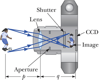
| The camera | In a camera lens, converging lens used to produce a real image of an object on a film (or array of 'pixels' in the case of a digital camera). The position of the lens is adjusted to focus the image on the film. - For a distant object the distance from the lens to the film must be equal to the focal length of the lens. - The nearer the object is to the lens the greater the distance from the lens to the films. |
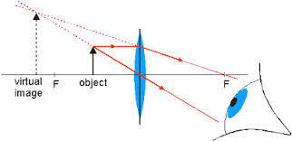
| Formation of a virtual image by a converging lens | Object must be between the lens and its principal focus, the image is formed on the same side of the lens to the object. The image is virtual, upright and larger than the object. The image can only be seen by looking at it through the lens, how a magnifying glass works. |
| Formation of a virtual image by a diverging lens | Image formed by a diverging (concave) lens is always virtual, upright and smaller than the object, a diverging lens is shown with a line with inward arrows. |
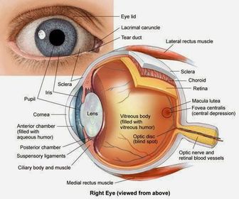
| Inside the eye | Light enters the eye through a tough transparent layer called the cornea which protects the eye and helps to focus the retina - a layer of light sensitive cells at the back of the inside of the eye. Amount of light entering eye controlled by iris which adjusts the size of the pupil - circular opening at the centre of the iris. The eye lens focuses light to give a sharp image of the retina although the image on the retina is inverted the brain interprets it as so you can see right away up. Aqueous humour - transparent watery liquid that supports the front of the eye. Ciliary muscles - attached to the lens by suspensory ligaments, the muscles change the thickness of the eye lens. Eye muscle - move the eye in the socket. Optic nerves - carries nerve impulses from the retina to the brain. There is a blind spot where the retina isn't sensitive sensitive to light (no light sensitive cells present), vitreous humour - transparent jelly like substance that supports the back of the eye. |
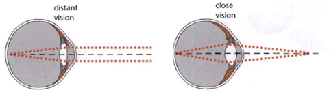
| How the eye focuses on different objects at different distances | Eye lens automatically become thinner to allow you to focus on far objects. The ciliary muscles alter the thickness of eye lens, attached to the edge of the lens by suspensory ligaments. Fibres of the ciliary muscles are parallel to the circular edge of the lens, when the contract they shorten and squeeze the eye lens making them thicker. Normal human eye has range of vision from 25cm to infinity, can clearly see objects further than 25cm or more from the eye. The normal eye has a near point of 25cm and far point of infinity. To see a nearby object the eye must be thicker than if the object is far away. |
| Lens power | Power of lens defined as 1/focal length in metre Unit of power is the dioptre (D), type of lens indicated by: - A positive value for a converging lens ex +0.5D for a converging lens of focal length of 0.2m - Negative value for a diverging lens ex -4D for diverging lens of focal length 0.25m. P=1/f P= lens power (D) f= focal length (m) |
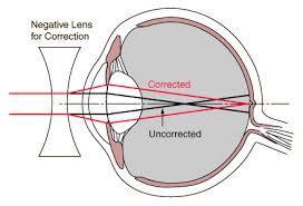
| Short defects | Occurs when an eye cannot focus on a distant objects, uncorrected image formed on retina. As the eyeball is too long or the eye lens is too powerful. Eye muscles cannot make the eye lens thin enough to focus the image of a faraway object on the retina of the eye. Eye can focus nearby objects so defect referred to as 'short sight'. Short sighted corrected by placing a diverged lens of a suitable focal length in front of the eye, the diverging lens counteracts some of the excess focusing power of the eye lens. |
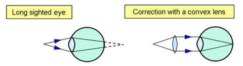
| Long sight | Occurs when an eye focuses on nearby objects, the uncorrected image is formed behind the retina, eye lens cannot be made thick enough to focus on image on the retina. Eye can focus distant objects so the defect referred to as 'long sight'. This is corrected by placing a converging lens of a suitable focal length in front of the eye. Correcting lens make the rays from the object diverge less. Eye len can then focus on the rays onto the retina, the correcting lens adds to the focusing power of the eye lens. |
| Comparison of eye and camera | How compare as optical instruments similar as both contain a converging lens which form a real image. The Eye: Has a variable focus converging lens Ciliary muscles alters the lens thickness A real, inverted image with a magnification less than one Image detection by light sensitive cells on the retina Brightness control by iris controlling the width of the eye pupil The camera: Has fixed focus converging lens Can adjust focus adjustment by adjusting lens position Is a real, inverted image with a magnification less than 1 Has photographic film for image detection (or CCD sensors in a digital camera) The brightness can be controlled by adjusting the aperture 'stop' - I don't know what that means |
| Lens makers at work | Eye len is remarkable optical device, has a variable focus length dependant on its thickness. Lens makers working for opticians need to make contact lenses and spectacle lenses exactly the right shape to obtain the exact focal length for each lens. Focal length of lens depends on the refractive index of lens material and the curvature of the two lens surfaces. Larger the refractive index or the greater the curvature of the lens surfaces, the greater the power of the lens (and shorter it's focal length). For a lens of a given focal length the greater the refractive index of the lens material, the flatter and the lens can be manufactured as lens surfaces would be less curved. |
| Moments | The turning effect of the force, called the moment of the force, can be increased by: - Increasing the size of the force - Using a longer lever |
| Lever | Crowbar's a lever used to raise a heavy object, weight of object is the load, the force the person applies is the effort. Using a crowbar the effort required to lift the load is only a fraction of the object's weight. Point at which the crowbar turns is the pivot or fulcrum. Line along which a force acts is its line of action. Work out the moment of a force using the equation: moment = force * perpendicular distance from the line of action of the force to the pivot (newton-metres, Nm) = (newtons,N) * (metres,m) M=F *d |
| Centre of mass | Can think of the object of an object at a single point this point is called the centre of mass (or centre of gravity) of the object. Centre of mass of an object is that point at which the mass be thought to be concentrated. |
| Suspended equilibrium | If object suspended then released will come to rest eventually with it's centre of mass directly below the point of suspension - object is then in equilibrium, it's weight doesn't exert a turning effect as its centre of mass is directly below the point of suspension. If object is turned from this position and then released will swing back to its equilibrium eventually as it's weight has a turning effect that returns the object to it's equilibrium say object is freely suspended it returns to it's equilibrium. |
| Centre of mass of a symmetrical object | For a symmetrical centre of mass is along the axis of symmetry. If the object has more than axis of symmetry, it's centre of mass if where the axis meet. - Rectangle has two axes of symmetry, centre of mass is where the axes meet - Equilateral triangle has three axes of symmetry each bisecting one of the angels of the triangle, the three axes meet at the same point, where the centre of mass of the triangle is. |
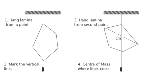
| Centre of mass test | How to find centre of mass of an irregular shaped flat card, card should be at rest freely suspended from a rod. It's centre of mass is directly below the rod, a 'plumbline' can be used to draw a vertical line on the card from the rod downwards. Procedure repeated with the card suspended from a second point to give a similar line, the centre of mass on the card is where the two lines meet. To check accuracy could draw a third line and see if intersect at the same point. To test the results it could be identified if it's possible to balance the card at this point on the end of a pencil. |
| Moments in balance | Seesaw example of where clockwise and anticlockwise moments might balance each other out. Which is possible by having the heavier object being a shorter distance from the fulcrum so that the clockwise moment balances out the anticlockwise moment. |
| Model seesaw | Ruler is balanced horizontally by adjusting the position of the two weights When it's balanced: the anticlockwise moment due to W1 about the pivot = W1d1 and the clockwise moment due to W2 about the pivot = W2d2 Anticlockwise moment due to W1 = the clockwise moment due to W2 hence: W1d1=W2d2 Seesaw example of the principle of moment which states for an object in equilibrium: the sum of all the clockwise moments about any pivot = the sum of all anticlockwise moments about that pivot Ex: Calculate W1, if W2 =4N d1= 0.25m and d2= 0.2m. S: Rearrange W1d1=W2d2 gives W1=W2d2/d1 = 4N*0.2m/0.25m = 3.2N (Remember to ensure units in calculations are consistent) |
| Measuring the weight of a beam | Can measure the weight of a beam by balancing it off centre using a known weight. Weight of beam acts at its centre of mass which is distance d0 from the pivot. Moment of the beam about the pivot = W0d0 clockwise where W0 is the weight of the beam The moment of W1 about the pivot =W1d1 anticlockwise where d1 is the perpendicular distance from the pivot to the line of action W1. Applying the principle of moments gives W1d1 = W0d0 - can calculate W0 if W1, d1 and d0 is known. |
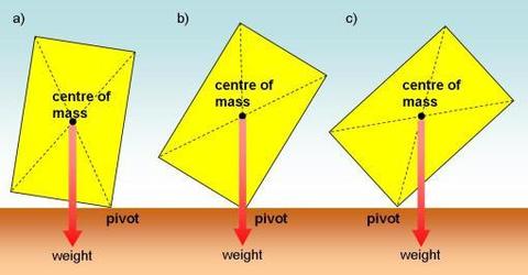
| Tilting and toppling objects | If you tilt an object slightly and release it, the turning effect of its weight returns it to its upright position. If you tilt the object more, you can balance it on its edge as it's centre of mass is directly above the edge on which it balances - it's weight has no turning effect in this position. If the object is tilted even more the turning effect of the bricks weight will cause it to topple over when released because it's line of action of it's weight is outside it's base. |
| Stability and safety | Many objects can topple over, many objects are designed for stability so they won't easily topple over. 1. Tractor safety - Doesn't topple over because the line of action of its weight acts within its wheelbase. If tilted more will topple over when it's line of action of its weight is outside it's wheelbase. As the moment about the lower wheel of the weight is clockwise. Moment of the support force from the ground on the upper wheel is clockwise, so the resultant moment about the lower wheel makes it topple over. |
| Stability and safety 2 Bus tests | Buses can be tested for how much can tilt before without toppling on a raised platform. These are important to ensure buses are safe to travel on, especially when they go round bends an on hilly roads - explanation why topples over is like in tractor. |
| Stability and safety 3 High chairs | High chairs for infants must have a wide base, when the child is sitting on it the centre of mass is above the seat, if the base were narrow and the child was strapped in the chair would topple over when the child leant sideways too much - why should have a wide base. Chair topples over if the child's weight acts outside the chairs base on one side, the high chair will turn about the position where the chair legs on that side are in contact with the floor - toppling happens if the moment of the child's weight about this position is greater than the moment of the chair's weight. |
| How to stop an object toppling over | To prevent toppling the centre of mass should be as low as possible and: - either the base should be wide enough to prevent toppling when the object is tilted or knocked sideways - or the base should be bolted or clamped down. If an object isn't clamped down, the line of action of it's weight lies outside its base the object will topple over as there is a resultant moment on the object. The object topples over as the sum of clockwise moments about any point isn't equal to the sum of anticlockwise moments about that point. |
| Hydraulics: About pressure | Defined as pressure per unit of area, unit of pressure is pascal (Pa) which is equal to one newton per square metre (N/m^2). For a force of F acting evenly on a surface of area A at right angles to the suface, the pressure p on the surface is: pressure = force/area |
| Pressure in liquids | Pressure in a liquid acts equally in all directions, in a bottle with holes at the same height water will flow out of the water a the same rates. |
| Hydraulic machines | Mechanical diggers use to remove quantities of earth ex. removing soil from over underground pipe. 'Grab' system operated by a hydraulic pressure system its it muscle power. Oil pumped into upper and lower parts of the cylinder to make the piston move in or out of the cylinder. Liquid virtually incomprehensible, won't change volume under pressure so pressure in a hydraulic system can be transmitted through the oil why force exerted moved from one place to another. |
| Hydraulic car jerk | Can be used to lift cars, when handle pressed down oil is forced out of the narrow cylinder and into a wider cylinder, pressure of oil forces the piston in the wider cylinder outwards so the piston forces the piston forces the pivoted lever to raise the car. |
| Force of a hydraulic system is much greater than the force applied to it | Force applied to system is effort, force exerted by system is load, load is moved by a much smaller effort. Force acts on a piston in a narrow cylinder which creates a pressure P=F/A in the oil where A is the piston area. This pressure in the oil acts on the wider cylinder the exerted force by the system =PA where A is the piston area. Hence the force exerted by the system = force applied to the system/ area of narrow cylinder * Area of wider cylinder. The force exerted by the system is therefore greater than the applied force as the area of the wider cylinder is much greater than the area of the narrower cylinder. So the hydraulic system is a force multiplier. |
| Circular motion | Ex. Vehicle on roundabout, satellite across the sky round the earth, fairground ride, athlete throwing hammer spinning before released. For an object moving in a circle at constant speed at any instant: - Object's velocity is directed along a tangent to the circle - Velocity changes direction as it moves around - Change of velocity is toward the centre of the circle. Object therefore accelerates continuously towards the center of the circle, the acceleration changes the direction of motion of the object, not its speed. As acceleration always acts towards the centre of the circle call it a centripetal acceleration. So resultant force on the object acts towards the centre of the circle. |
| Centripetal force | Object moving in a circle must be acted on by resultant force acting towards the centre of the circle. Call the resultant force a centripetal force as it always acts towards the centre of the circle: - Centripetal force on a vehicle moving around a roundabout is due to friction between tyres and the road. Person in London Eye capsule moves round at constant speed the centripetal force on the person acts towards the centre of the 'wheel' the force is the resultant force of the person's weight and the support force from the floor. Fairground gravity wheel starts of spinning horizontally when it's spinning fast enough the wheel is turned until it's spinning vertically. Riders are strapped in to the inside of the wheel. When a rider is near or at the top of the wheel they experience a downward push from the wheel to keep them moving in a circle. The centripetal force is due to the weight of the rider and the downward push from the wheel on the rider. |
| Centripetal force factors | Centripetal force increases when the speed of the object increases. Centripetal force increases if the circles radius decreases. The greater the mass of the object the greater the centripetal force. Centripetal force is a force in it's own right, it's the resultant force acting on an object moving in a circle. |
| The pendulum | The position where an object moves fastest on a pendulum is it's equilibrium position this is also where the object comes to an eventual stop - the motion of an object on a pendulum is an oscillation motion, where the motion of the object moves to and fro along the same line. |
| Motion of a pendulum | Moves object along line between highest position A and C on each side, there is little air resistance on it or friction from at the point of suspension so it takes a long time to stop swinging. The amplitude of an oscillating object is the distance it moves from it's equilibrium position B to it's highest point at A or C. It's time period is the time taken for one complete cycle: time taken to swing across from it's highest position on one side - C to A then to A Time between successive passes in the same direction through its equilibrium position B. |
| Frequency of oscillations in a pendulum | The time period of a pendulum is dependant on it's length and increases as it's length does. The frequency of the oscillations is the number of complete cycles of oscillations per second. Unit of frequency is hertz where 1 hertz is 1 cycle per second. The greater the frequency of oscillations the shorter the time period. the time period (seconds, s) = 1/frequency of oscillations (hertz, Hz) T=1/f |
| About magets | A magnetic compass is a tiny magnetic needle pivoted at its centre because of the Earth's magnetic field one end of the compass always points north and the other south. The end that points north is called the north pole and the other end the south pole. Like poles repel; unlike poles attract A magnet is a metal that has been magnetised examples are iron and steel and cobalt. The ends of the magnets are the magnetic poles. Iron fillings near a magnet form a pattern of lines the lines loop from one pole to another, say that there is a magnetic field around the magnet. We refer to the lines as lines of force or magnetic field lines. The direction the compass points tells us the direction of the field line, the lines always loop round from the north pole of the magnet to its south pole. |
| Electromagnets | This is made of insulated wire wrapped around an iron bar (the core) when a current is passed along the wire a magnetic field is created around the wire. By consequence the magnetic field of the wire magnetises the iron bar strongly, when the current is switched off the iron loses most of its magnetism. Iron easily loses its magnetism when the current is switched off, though steel is unsuitable as the core of an electromagnet as steel keeps its magnetism when the current is switched off. |
| The scrapyard crane | Scrap vehicles are lifted in a scrap yard using powerful electromagnets attached to cranes, the steel frame of a vehicle is attracted to the electromagnet when current passes through the coil. When the current is switched off, the steel frame drops off the electromagnet. |
| The circuit breaker | The is a switch in a series circuit with an electromagnet, the switch is normally held in place by an iron catch when too much current passes through the electromagnet the switch is pulled open by the electromagnet and the switch opens, it stays open until it's reset manually. |
| The electric bell | When the bell's connected to the battery, the iron armature is pulled on to the electromagnet, this opens the make and break switch and the electromagnet is switched off. By consequence the armature springs back and the make and break switch closes again so the whole cycle repeats itself. |
| The relay | This is used to switch an electrical machine like a motor on and off, when a current passes through the electromagnet, the armature is pulled on the electromagnet as a result the armature turns about the pivot and closes the switch gap, in this way a small current through the electromagnet is used to switch on a much larger current. |
| The motor effect | Use electric motors lots each day ex. hairdryer, electric shaver, computer hard drive - all these appliances contain an electric motor. The electric motor works because a force can act on a wire in a magnetic field when a current is passed through the wire, called the motor effect. you should find that a force acts on a wire in a magnetic field unless the wire is parallel to the magnetic field lines. |
| Force factors | The size of the force can be increased by: - increasing the current - using a stronger magnet Size of the force depends on the angle between the wire and the magnetic field lines, the force is: - greatest when the wire is perpendicular to the magnetic field - zero when the wire is parallel to the magnetic field lines. The direction of the force is always at a right angles to the wire and the field lines, also, the direction of the force is reversed if the direction of the current on the magnetic field is reversed |
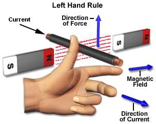
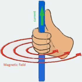
| Fleming's left-hand rule | Hold fingers at right angle to each other, can use rule to identify the direction of the force (movement) on the wire. First finger = Field Second finger = Current Thumb = Movement |
| Right hand rule | |
| The electric motor | This is designed to use the motor effect it's possible to control the speed of an electric motor by changing it's current, we can also reverse the direction the motor turns in by reversing the current. A simple motor consists of a rectangular coil of insulated wire (the armature coil) that's forced to rotate. The coil is connected through two metal or graphite 'brushes' to the battery, the brushes press onto the metal 'split-ring' commutator fixed to the coil. When a current is passed through the coil, the coil spins as: - a force acts on each side of the coil due to the motor effect - the force on one side is in the opposite direction to the force on the other side The split-ring commutator reverses the current around the coil every half turn of the coils as the sides swap over each half-turn, the coil is pushed in the same direction every half-turn. |
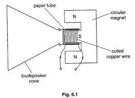
| The loudspeaker | This is designed to make a diaphragm attached to a coil vibrate when alternating current passes through the coil. When a current passes through the coil, a force due to the motor effect makes the coil move. Each time the current changes its direction the force reverses its direction so the coil is repeatedly forced backwards and forwards, this motion makes the diaphragm vibrate so sound waves are created. |
| Electromagnet induction | Hospital has its own electricity generator always on 'standby' in case of a power cut the patient's lives would be put at risk if the mains electricity supplied failed and there was no standby generator. A generator contains coils of wire that spin in a magnetic field, a potential difference or voltage is created or induced (use this word it sounds fancy) across the ends of the wire when it cuts across the magnetic field lines. Call this process electromagnetic induction, if the wire is part of a complete circuit the induced pd makes an electric current pass round the circuit. |
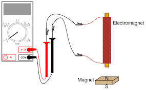
| A generator test | When one end of a bar magnet is pushed into a coil of insulated wire connected to a centre-reading ammeter the ammeter pointer deflect as the movement of the bar magnet causes an induced pd in the coil and the induced pd causes a current as the coil is part of a complete circuit. |
| A magnetic puzzle | Using two separate lengths of insulated wire to make two coils on a cardboard tube with one coil connected to a battery in series and the other to an ammeter it can be found that: 1- When the switch is closed the ammeter pointer briefly deflects switching the current on creates a magnetic field that passed through both coils so the effect on the coils with the ammeter is the same as pushing a magnet into it the pd is induced. 2- Keeping the switch is closed the ammeter point doesn't deflect as the current in the series circuit is now constant so the magnetic field doesn't change the effect on the coil with the ammeter is the same as when a magnet is held stationary to it, the magnetic field of the electromagnet has to be changing to induce a pd. With an iron bar as the core the deflection is much larger. |
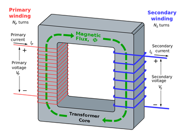
| Transformers | Typical power station generator produces an alternating potential difference of about 25000 volts, mains electricity to homes is at 230 volts. When an appliance is plugged into the mains the electricity to run it comes from a power station. The electricity arrives through a network of cables called the National Grid. The alternating pd of the cables (the grid voltage) is typically 132000 volts. A transformer is used to change the size of the alternating pd. |
| How a transformers work | A transformer has two coils of insulated wire both wound round the asme iron core. The primary coil is connected to an alternating current supply when alternating current passes through the primary coil an alternating pd is induce in the secondary coil. Which occurs because: - alternating current passing through the primary coil produces an alternating magnetic field - the lines of the alternating magnetic field pass through the secondary coil - the magnetic field is changing Which creates an alternating potential difference between the terminals of the secondary coil, say an alternating potential difference is induced to the secondary coil. If a bulb is connected across the secondary coil the induced pd causes an alternating current in the secondary circuit, so the bulb lights up. Electrical energy is therefore transferred from the primary to the secondary coil, which happens even though they aren't electrically connected in the same circuit. |
| Step up and down transformers | Step-up transformer makes the pd across the secondary coil greater than the pd across the primary coil - its secondary coil has more turn than it's primary coil (more coils) Step-down transformer makes the pd across the secondary coil less than the pd across the primary coil - its secondary coil has fewer turns than its primary coil (fewer coils) Ex. Use a step-down transformer in a low-voltage supply to step the mains pd from 230V |
| Transformers in action | These only work with alternating current, with a direct current there is no changing magnetic field so the secondary pd is zero. In a transformer with a direct current the core of the transformer 'guides' the field lines in a loop through the coils, but the field must be changing to induce a pd in the secondary coil. In a practical transformer the primary and secondary coils are both wound round the same part of the core. The core is layered (laminated) to cut out induced currents in the iron layers. if it wasn't laminated the efficiency of the transformer would be greatly reduced. |
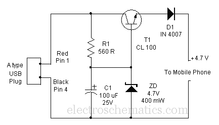
| Switch mode transfomers | This works in a different way to the traditional transformer it operates at frequencies between 50000Hz (50kHz) and 2000000Hz (200kHz), its main features make it suitable for use in mobile phone chargers. -It's lighter and smaller than a traditional transformer which works at 50Hz -Uses very little power when there is no device connected across its output terminals. Mobile phone chargers has three main circuits: From the mains input of 230V and 50Hz the frequency converter, the switch mode transformer and the low voltage ac to dc convertor owing to direct voltage output at low voltage. The switch mode transformer has a ferrite core, which is much lighter than an iron core and unlike an iron core can work at high frequency, the circuis convert the mains pd (at 230V and 50Hz in Europe) to a much lower direct pd |
| Transformers in action again | Use mains appliances the electricity is supplied to us through the National Grid from distant power station. The higher the grid pd, the greater the efficiency of transferring electrical power through the grid. Why transformers are used to step up the pd from a power station to the grid pd and to step the grid pd down to the mains voltage. The grid pd is at least 13200 V, if the difference in pd were much lower much more current would be needed to deliver the same amount of power, the grid cables would therefore heat up more and waste more energy. |
| The transformer equation | The secondary pd of a transformer is dependant on the primary pd and the number of turns on each coil. Can use the following equation to calculate any one of these factors if we know the others. pd across primary, Vp/ pd across secondary, Vs = number of turns on primary, np/ number of turns on secondary, ns For a step-up transformer the number of secondary turns, ns, is greater than the number of primary turns, np. Therefore Vs is greater than Vp. For a step-down transformer the number of secondary turns, ns, is less than the number of primary turns, np. Therefore Vs is less than Vp. |
| Transformer efficiency | Transformers are almost 100% efficient when a device is connected to the secondary coil almost all the electrical power supplied to the transformer is delivered to the device. We know how much electrical power device requires to work normally this tells us how much electrical power must be supplied to the transformer. - Power supplied to the transformer = primary current, Ip * primary pd, Vp - Power delivered by the transformer = secondary current, Is * secondary pd, Vs Hence for 100% efficiency: power supplied to the transformer = power delivered by the transformer primary pd * primary current = secondary pd * secondary current Vp * Ip = Vs * Is |
| A physics case study | Use many devices in hospitals to find out why patients are unwell and help them recover, in this case study, look at the physics of some of these devices. A patient has a swollen neck and the doctor are doing test to find out what has caused it, the swelling is affecting his breathing so they need to closely monitor the condition. Initial tests: 1. An endoscope is inserted through a nostril to check that the airway in the throat is clear 2. His blood pressure is electronically measured 3. An ECG or electrocardiogram is recorded this is a chart showing how the pd generated by the heart varies with time. The doctor in charge of the patient tells the patient his airway is clear and blood pressure normal. The ECG test shows there are no problems with his heart and blood circulation. A sample of fluid is taken from the fluid using a fine needle, the sample is tested in the pathology lab which indicates that there may be a cyst or fluid in the affected area. So the patient needs to have some scans of the affected area. |
| Physics case study: Scans | These include ultrasonic scans, X-ray CT scans, and magnetic resonance (MR) scans. The patient needs: 1. X-ray CT scan to see if there are other affected areas in the neck or the chest, the operator or radiographers must wear film badges to monitor and record their exposure to ionising radiation. 2. MR scan to see exactly where the swelling is located; an MR scan uses radio waves, these waves unlike X-rays are non ionising. The CT scan shows that no other areas are affected - with the exact position known from the MR scan, the cyst is then removed surgically. |
Want to create your own Flashcards for free with GoConqr? Learn more.