19782860
Description
Flashcards by Alice Kimpton, updated more than 1 year ago
|
|
Created by Alice Kimpton
over 4 years ago
|
|
| Question | Answer |
| - Envelope: - Envelope flows: - Internal flows: - Natural ventilation: - Prupose-provided openings: - Advantaous openings: - Infiltration: - Exflitartion: | envelope – the fabric that encloses the air (internal and external walls that comprise a zone) envelope flows – airflow through openings in the envelope internal flows – airflows exclusively inside the envelope natural ventilation – envelope flow driven by natural forces (wind and buoyancy) purpose-provided openings – openings in the envelope that are intentional e.g. vents, open windows, stacks. adventitious openings – unintentional openings in the envelope e.g. gaps and cracks in walls and windows infiltration – uncontrolled airflow in through adventitious openings exfiltration – uncontrolled airflow out through adventitious openings |
| List the hierarchy of ventilation systems: | • Natural Ventilation • Local Mechanical Ventilation e.g. extract hoods, desk fans • Mechanical Ventilation (ducted) – extract only – supply only – extract + supply (balanced or unbalanced) • Air Conditioning – ducted mechanical system with cooling and humidity control • Mixed-mode (hybrid, assisted natural) – zoned: different systems in parts of the building – complementary: operated at different times – contingency: designed to be adaptable |
| What should you you do before using mechanical solutions? | “Before investing or proposing new mechanical solutions, traditional solutions in vernacular architecture should be evaluated and then adopted or modified and developed to make them compatible with modern requirements.” |
| Advantages of natural ventilation: | - Zero running costs - Lower capital and maintenance costs than MV systems - Lower GHG emissions than MV systems - Does not require space for plant room and duct work - Evidence that occupants prefer to exercise control over their environment via NV (lower incidences of SBS) - Allow implementation of adaptive thermal comfort approach |
| Disadvantages of natural ventilation: | - Difficult to design (specialist knowledge required) - Errors difficult to correct (mixed-mode offers correction) - Airflow rates are variable – What do you do on a hot still summer’s day? (depends on temperature difference, wind speed and orientation) - Less control over the internal thermal environment - Imposes restrictions on the building layout - Some clients may be have a low opinion of NV - Winter heat loss - Noise ingress - Security |
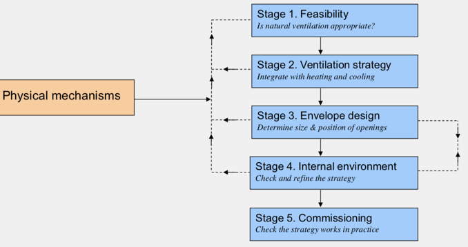
| Design process diagram | |
| Feasibility points: | 1. Climate 2. Heat gains 3. Occupants 4. Building geometry and environment 5. Building plan and layout 6. Building envelope 7. Thermal storage (night cooling) 8. Control |
| Climate: - Steady state conditions - Transient weather file | 1. Steady state conditions (based on local extremes) 2. Transient weather file (usually with hourly resolution) • external temperature (dry bulb) • relative humidity (or air pressure and wet bulb temperature) • wind speed and direction • external pollutant concentration • global and diffuse radiation • cloud cover |
| Climate: Data sources? | CIBSE Test Reference Year (TRY) A synthesised typical weather year suitable for analysing energy use and overall environmental performance Typical weather conditions for each month Used for UK school design (see BB101 section 1.7) CIBSE Design Summer Year (DSY) An actual year containing a near-extreme summer recommended by CIBSE for use in overheating assessment A year with a hot, but not extreme, summer See CIBSE Guide J: Weather data |
| Climate: What has to be done for climate weather data? | |
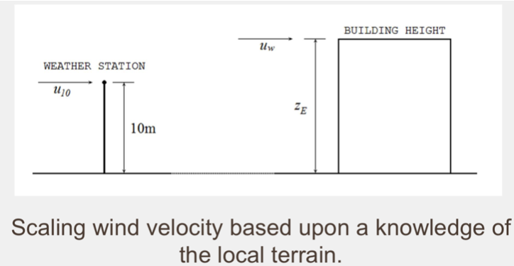
| Climate: Modified wind speed | • Wind speed increases with height above ground level. • Wind speed is measured at a location that offers little resistance to its movement and is used in weather files • Wind speed in weather files requires modification to reflect the wind speed that might be found in-situ. |
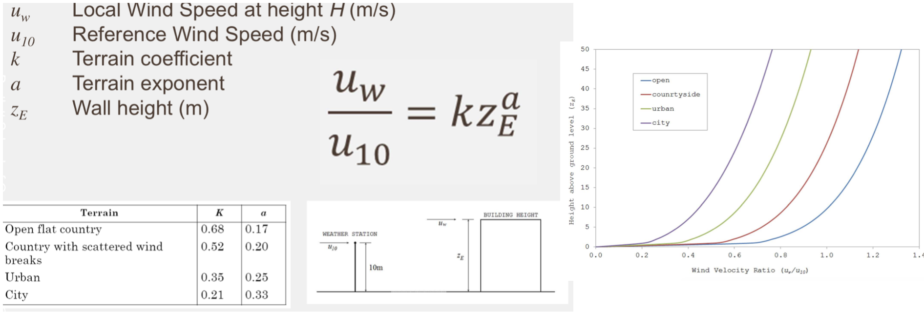
| Climate: Modified wind speed equation | |
| Internal heat gains: Preventing over heating strategies | Minimise heat gains to less than 30-40W/m2 High ventilation rates during occupancy Night cooling (low during day, high at night) – reduction of humidity – a difficult problem – variability of ventilation flow rates |
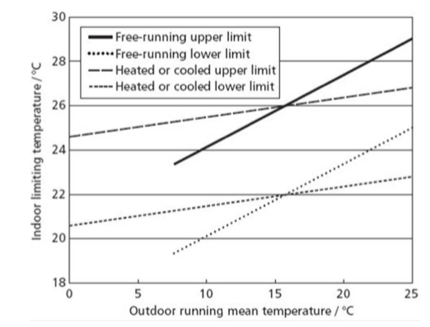
| Internal heat gains: Why are occupants important? | Occupant behaviour is very important: – actions to modify opening areas – adaptation (active) to modify clothing and activities – adaptation (passive) to comfort criteria are not rigid |
| Building geometry and environment: What creates pressure distribution around a building? | 1. Building geometry 2. Wind direction 3. Local environmental conditions |
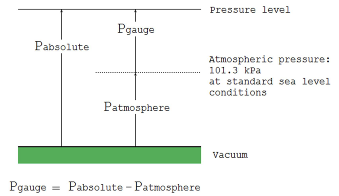
| Building geometry and environment: What is Pgauge equal to? | |
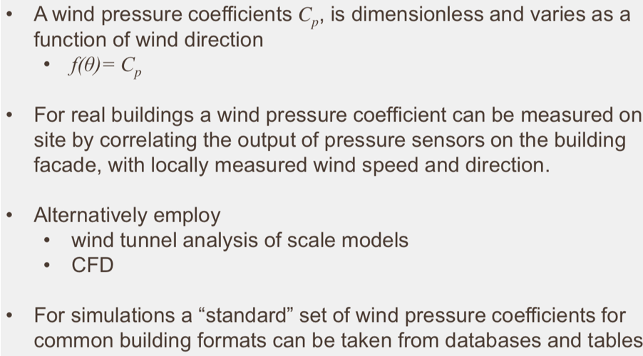
| Building geometry and environment: - What is the wind pressure coefficient? - How can wind pressure babe measured? - Alternatively? - What about for simulations? | Wind pressure is how much energy is given to the facade. Its never 0 or 1. |
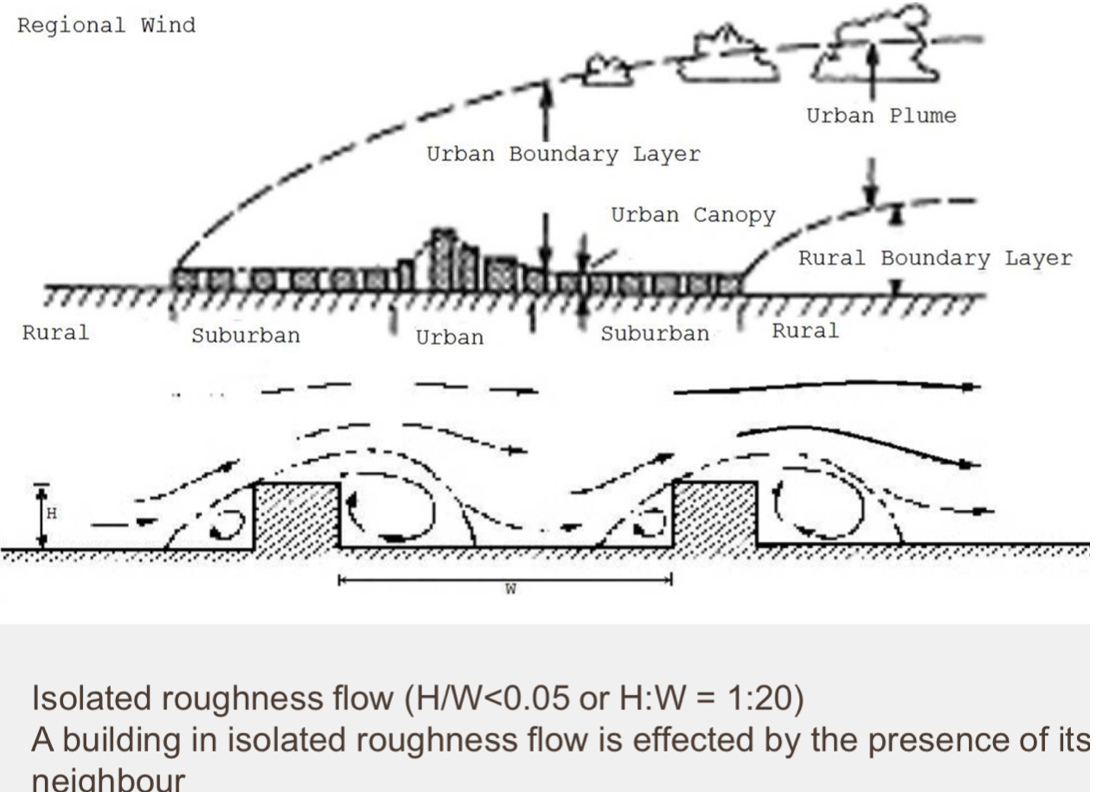
| Building geometry and environment: Diagram of regional boundary layers? Diagram of isolated roughness flow? What is a bu8ilding of isolated roughness effected by? | Layer of turbulence from the first building. |
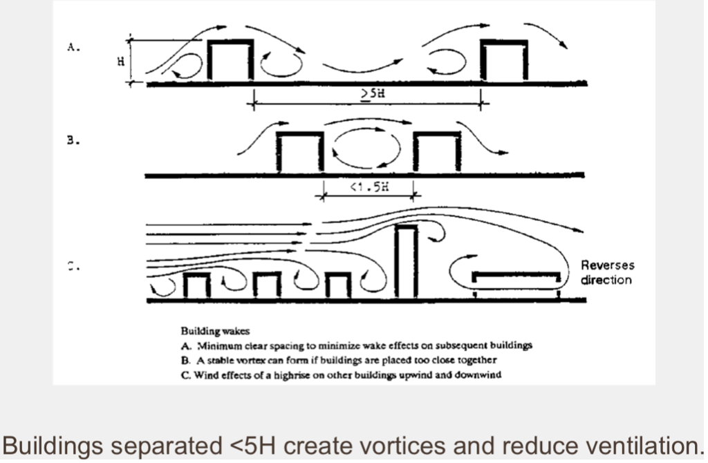
| Building geometry and environment: Diagram of building wakes What can wakes do? | Wakes can reduce ventilation depending on orientation. If the buildings are closer than 5H, they’ll interact with each other. |
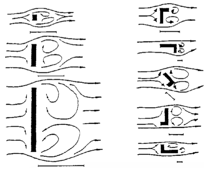
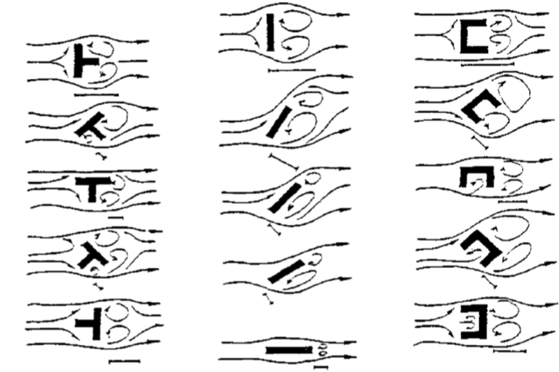
| Building plan and layout: Wakes induced by different forms. The first is: | |
| Building plan and layout: Wakes induced by different forms. The second is: | |
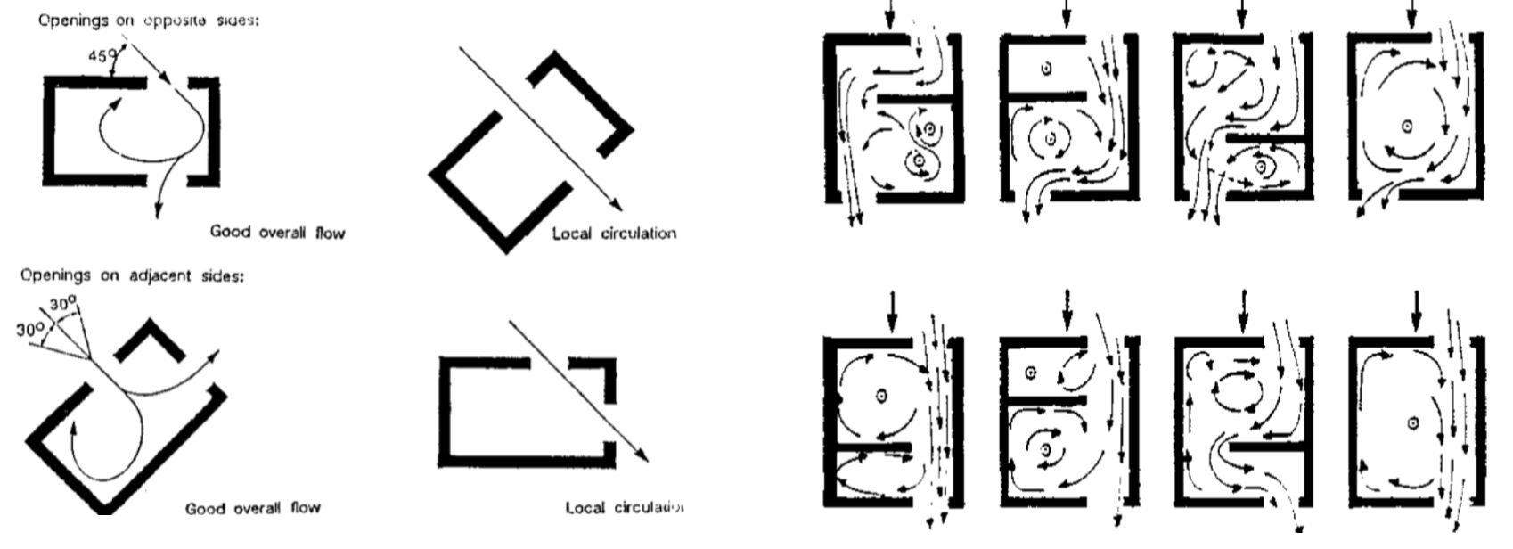
| Building plan and layout: Effect of incidence angle of internal flow (1 of 2): | i.e. openings and breaking up the indoor environment. |
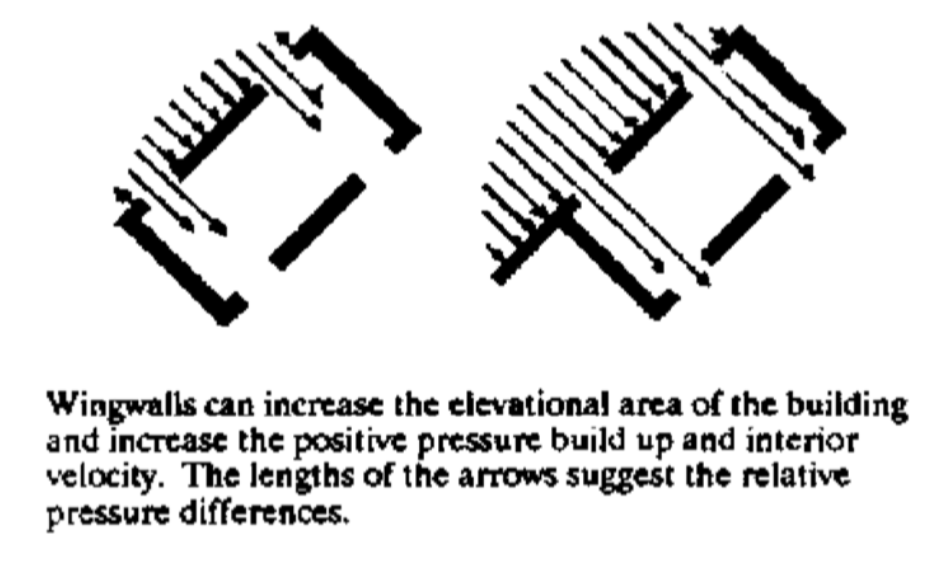
| Building plan and layout: Augmenting positive pressure and internal air velocity using Wingwalls diagram | - don’t want velocity above 0.25m/s for comfort. |
| Building plan and layout: - In deep plan buildings, what are the issues and how can they be resolved? | - Deep plan buildings are a problem, because the entry of fresh air is concentrated at the external envelope - Cross-flow ventilation can be used - This can be achieved through adding an atrium, which can add natural ventilation system and add daylight, |
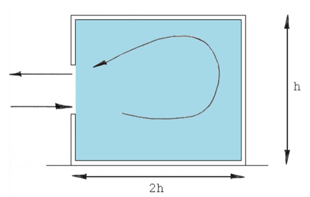
| Building plan and layout: Side sided room diagram | - Height to depth ratio 2:1 |
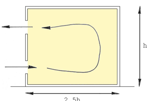
| Building plan and layout: Single sided double opening layout | - 1m between openings |
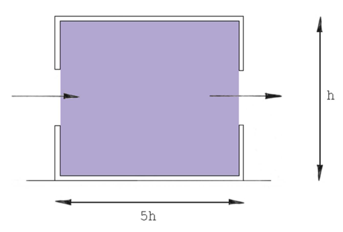
| Building plan and layout: Cross ventilation room diagram | - 5:1 height to width ratio |
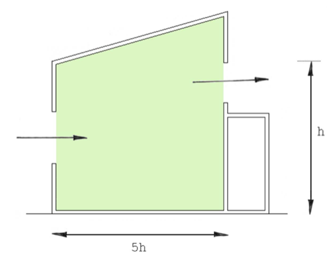
| Building plan and layout: Clerestory room diagram | - horizontal facade |
| Building plan and layout: Stack | Insert image of a stack. - vertical facade |
| Building plan and layout: Can high rises be naturally ventilated? How? | High-rise buildings can be naturally ventilated by isolation of the individual floors – residential apartment blocks. Natural ventilation of very tall buildings (skyscrapers) is feasible, but very rare. When the floors are connected, the building acts as a single space - segmentation needed. |
| Building envelope: Why is it one of the most important factors? | - Provides thermal storage - Influences internal solar gains - Contains the purpose-provided openings |
| Building envelope: What is adventitious leakage? | – Unintentional ventilation due to leakage from: – Window/door frames and joints – Through-wall ducting and pipework – Poor fabric condition – important when purpose-provided openings are small – typically in winter (heating) season – accounting for leakage in design (see next lecture) |
| Building envelope: What else occurs through the envelope apart from adventitious leakage? | - No heat recovery in natural ventilation (can’t filter with natural ventilation) - Increases heat demand - Reduces control of ventilation - Follow mantra of “Build Tight Ventilation Right” |
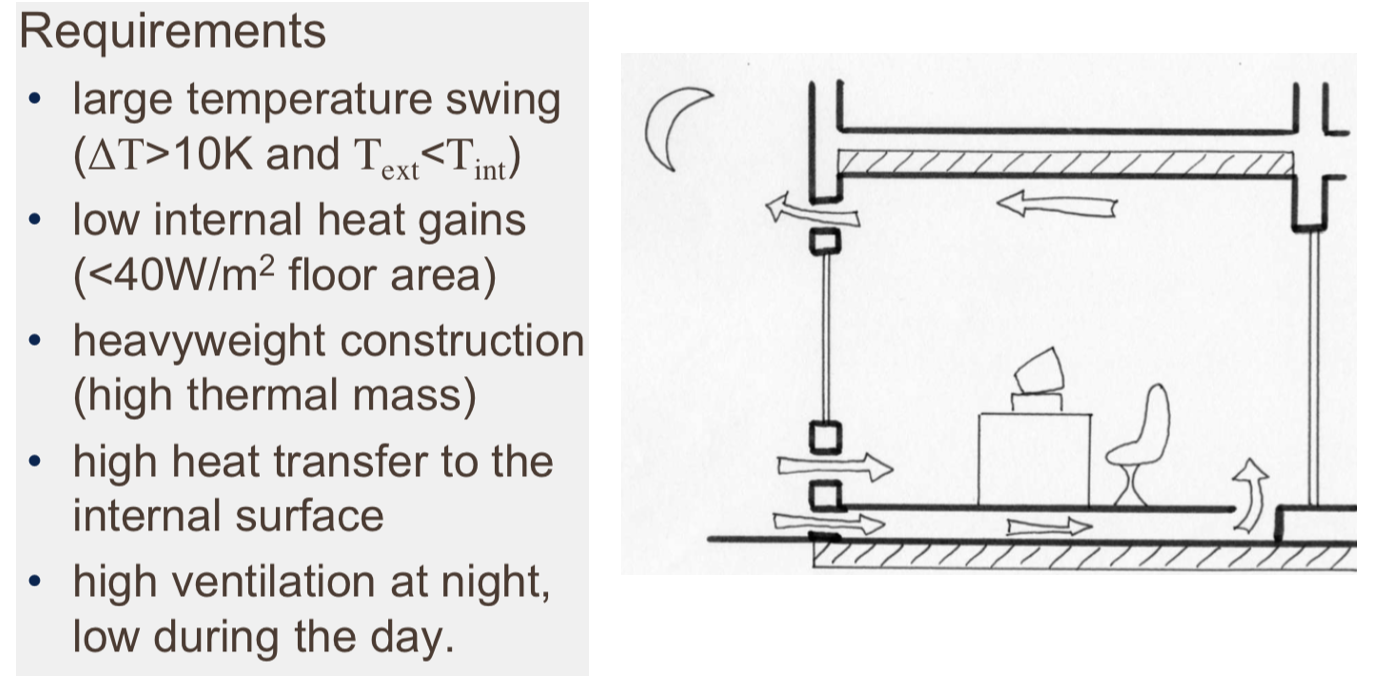
| Thermal storage: Requirements | Brings air into the building when the air temperature outside is much colder than inside. In lightweight there is no energy to dissipate. |
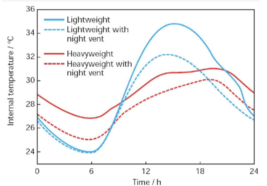
| Thermal storage: Diagram of thermal mass on peak indoor temperature | |
| Control: - By design - By mechanical devices | By design: – openings are sized (maximum and minimum values) so that they allow the occupants to exercise control – required flow pattern (the ventilation strategy) is fixed for most weather conditions By mechanical devices: • Building Management System e.g. temperature or CO2 sensor • constant flow vents We usually size for openings for the openings. |
| Control: - Other options | • Label clearly • Locate controls together • Locate sensibly – Near where occupants will work – Away from disturbances (direct sun light or other heat sources if temperature sensitive) |
| What does the term strategy refer to? | The term strategy refers to the flow pattern of air as it passes through envelope openings (internal and external surfaces) |
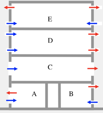
| What are the 2 basic categories of internal space? | 1. isolated spaces - separate (in terms of airflow)from other parts of the building - openings to other parts of the building small in relation to openings in the external envelope 2. connected spaces - form a single-cell-large internal openings - flow through any opening depends on the flow through the other openings Different strategies may be required at different times |
| Isolated spaces - What are the 2 basic types? | 1. single-sided – spaces A and B 2. cross-flow – floors C and D – floor E (buoyancy alone) |
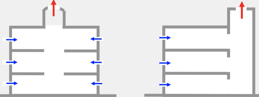
| Connected spaces: single cell building: - Atrium/tower | An atrium or tower is used to generate in ward flow of fresh air into all of the floors i.e. cross-flow ventilation. Wind and buoyancy act in unison to maintain flow pattern (not necessarily with “top-down” ventilation). |
| Connected spaces: single cell building: - Chimney - Duct walls - Wind catcher | - Chimney or stack is used to maintain flow pattern under all weather conditions (not “top- down” ventilation). - Duct walls can support horizontal variation in density (solar chimney, double-skin facade). - Modern “wind catcher” – balanced ventilator - inlet and outlet flows are equal for any wind direction |
| Connected spaces: single cell building: - Top down ventilation | – downward flow in stack or atrium is induced by buoyancy e.g. by applying cooling in the stack – passive downdraught evaporative cooling • Water sprayed at high level, which evaporates and cools the air • N.B. Wind effects should be taken into account – they can overcome buoyancy |
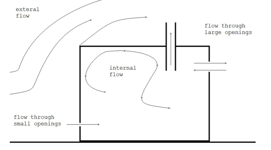
| Descriptions of Mechanisms: Ventilation of a building can be considered as comprising two processes :– | - envelope flow - the entry and exit of air through openings in the building envelope - internal air movement - the motion of the air inside the envelope |
| Descriptions of Mechanisms: What are the 3 cases? | Processes are dependent, but often treated separately Three cases: • buoyancy alone • wind alone • buoyancy and wind combined |
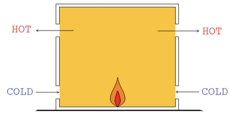
| Diagram of buoyancy alone (no wind) | |
| Buoyancy alone (no wind): - Envelope flow - Internal air motion | Envelope flow: • internal and external air pressures are given by the hydrostatic equation • density gradients in the horizontal directions negligible (ignored) Internal air motion: • momentum of the air flow through openings • buoyancy forces - heat transfer into the air at surfaces • internal velocities considered negligible (ignored) • air is considered to be perfectly mixed • But, stratification (vertical variation of density) is possible but often ignored (erroneously) |
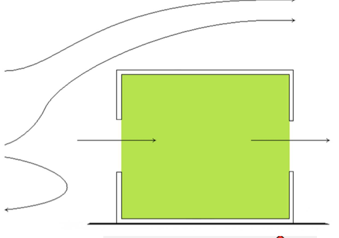
| Wind alone (uniform density) diagram | |
| Wind alone (uniform density): - Envelope flow - Internal air motion | Envelope flow: • pressure difference across the envelope due to spatial variation of external surface pressure Internal air motion: • turbulent • difficult to model theoretically – potential for scale modelling |
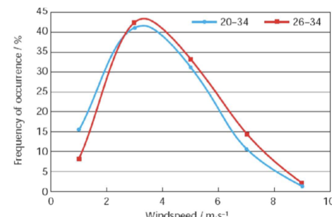
| Wind and buoyancy combined: - Graph - In general... | In general, buoyancy and wind act simultaneously and their individual solutions cannot be added. It is internal pressure that has to be solved for a combined case. |
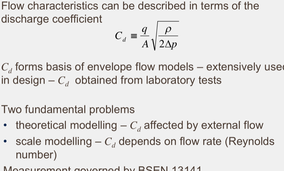
| Airflow through openings: - Equation for discharge coeffiecnt - Fundamental problems | assume cd = 0.61 (when it is actually too high!) Where q = cd A √2∆p / l Thus q = cd A √2/p Measures the pressure of flow. A = Aeff (effective area) |
| 3 basic mathematical models? | 1. envelope flow model – forms basis of initial design stage (Stage 3), also used in Stage 4 (next lecture) 2. computational fluid dynamics (CFD) – commonly used in later design stage (Stage 4) 3. model of the thermal behaviour of the building combined with an airflow model - commonly used in later design stage (Stage 4) |
| Sizing of openings: What is the aim for a chosen strategy? Why would we use the envelope flow model? | For the chosen strategy (flow pattern), the aim is to determine the sizes (and positions) of openings needed to give the required flow rates (magnitudes). Use an envelope flow model (using the explicit method) to determine the maximum and minimum sizes of openings required maintain control over a specified range of conditions. |
| Sizing of openings: Basic procedure | 1. divide building into isolated and connected spaces 2. specify flow pattern required (ventilation strategy) (arrows) 3. specify flow rates required (activity, heat gains) 4. specify the design weather conditions (for extremes) 5. use the explicit method to calculate the open areas to satisfy these requirements 6. select appropriate openings i.e. how big openings needs to be to supply air flow that has been stated. |
| Design conditions: - Climate with 2 seasons - What does the explicit method determine? | • In a climate with two distinct seasons that require heating and cooling, two basic design conditions exist – winter condition - determines the minimum sizes of the openings – summer condition - determines the maximum sizes. • For each design condition, the explicit method determines the sizes and positions of openings that will give the required flow rates (magnitude and direction). • In practice the explicit solution will rarely occur. It is necessary to look at off-design conditions. |
| Design conditions: In winter what must we ensure? What is the basic procedure? | • Ensure adequate indoor air quality • The basic procedure consists of the following steps:- (i) determine the minimum ventilation rates required for air quality (ii) decide "worst case" condition (wind speed, direction and temperatures) (iii) use the explicit method to calculate the open areas required (iv) select appropriate openings. • The areas obtained are basically the minimum sizes for the openings i.e. the type of openings should be chosen such that this area is permanently available. |
| Design conditions: In winter, what is the 'worst case'? | The choice of the "worst case" condition in (ii) is not clearly defined. – The choice should usually correspond to a high ventilation rate e.g. the designer might choose the weather conditions for which there is only a 1 in 10 chance of them being exceeded. – With less extreme conditions the occupants will be assumed to increase the openings as appropriate. |
| Design conditions: In winter, using the explicit method (iii) what must we use? Why not windows? | For (iii) it is preferable to make use of adjustable vents (e.g. “trickle” ventilators) which are additional to the openable windows. – Windows are not ideal for achieving small openings and the coarse control could lead to excessive ventilation. – The vents should be adjustable to an area which is two or three times the design minimum. |
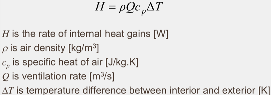
| Design conditions: In summer, what must be prevented? What is the basic procedure? | • Prevention of internal overheating The basic procedure consists of the following steps:- (i) decide acceptable peak temperature rise e.g. 3oC (ii) calculate the ventilation rate required to ensure that this temperature rise is not exceeded (ideally include thermal characteristics of building i.e. full thermal response calculation over 24hrs or more) (iii) take "worst case" to be zero wind speed (iv) calculate the open area required and design the openable windows such that this maximum value can be achieved. |
| Design conditions: Rate of internal heat gains equation | |
| Later design processes: - What conditions are used? - What types of tools are available? | • Off-design conditions • There is a wide range of design tools available, which can be summarised under the following headings – scale modelling – envelope flow models – computational fluid dynamics, CFD – combined thermal and airflow models |
| Computational fluid dynamics: Diagram | |
| Computational fluid dynamics: What are the most versatile design tools? | – Calculation of temperature and velocity fields in single and multi-cell buildings – calculation of air flow around buildings and surface wind pressure distributions – whole-field calculations i.e. the combination of the above – rare – component flows – i.e. chimneys-calculation of Cd |
| What are the uncertainities with CDF (computioanl fluid mechanics)? | • Potentially powerful • Detailed velocity and temperature fields • Age-of-air and contaminant concentration fields can be calculation • There are problems! – Sensitivity analyses (e.g. to boundary conditions) are rare – Uncertainty in the results is rarely quantified – Assumption of steady flow ignore the effects of the initial conditions – Sensitivity to the specification of the grid – Effects of the turbulence model employed – CFD calculations should only be carried out by experienced users – Results should be treated with caution • Boundary conditions A real flow satisfies conditions at its boundaries and develops with time from an initial condition • Steady state CFD assumes • solution is independent of the initial conditions • Unsteady CFD • numerical process is not the physical process • convergence may not occur, buoyancy is a problem • Uncertainties in boundary conditions, particularly with heat transfer, are a fundamental limitation • Assumptions in the equations – turbulence models – heat transfer at surfaces |
| Combined thermal and airflow models: - What is a major difficulty in design? - Are combinations available? | - A major difficulty in design is the calculation of internal temperatures - due to interaction between temperature (density) field and envelope flow rates. - Combinations of a ventilation model (envelope flow or CFD) and a thermal model are available. |
| Combined thermal and airflow models: - Do you use 2 models together? - What is a more simple way? - What is an issue? | - Ideally the two models would be completely integrated - the governing equations are solved simultaneously. - A simpler approach is to solve the two models separately, with some form of link between their solutions. - Stability can be a problem. |
| What can you conclude from this topic? | The overall design process consists of four stages: assess feasibility of natural ventilation – cooling is a major challenge 2. decide the ventilation strategy (or strategies) – night cooling may be desirable 3. determine the sizes of openings that give the required flow strategy and flow rates under design conditions – explicit envelope flow models are very useful 4. examination of off-design conditions – internal air motion is a major challenge - CFD |
Want to create your own Flashcards for free with GoConqr? Learn more.