5111145
Description
Flashcards by John Dedios, updated more than 1 year ago
|
|
Created by John Dedios
over 8 years ago
|
|
| Question | Answer |
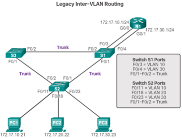
| In this legacy approach, inter-VLAN routing is performed by connecting different physical router interfaces to different physical switch ports. The switch ports connected to the router are placed in access mode and each physical interface is assigned to a different VLAN. Each router interface can then accept traffic from the VLAN associated with the switch interface that it is connected to, and traffic can be routed to the other VLANs connected to the other interfaces. | |
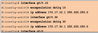
| Router-on-a-Stick Inter-VLAN Routing The router interface is configured to operate as a trunk link and is connected to a switch port that is configured in trunk mode. The router performs inter-VLAN routing by accepting VLAN-tagged traffic on the trunk interface coming from the adjacent switch, and then internally routing between the VLANs using subinterfaces. | The router then forwards the routed traffic, VLAN-tagged for the destination VLAN, out the same physical interface as it used to receive the traffic Subinterfaces are software-based virtual interfaces, associated with a single physical interface. Subinterfaces are configured in software on a router and each subinterface is independently configured with an IP address and VLAN assignment |
| Note: The router does not support the Dynamic Trunking Protocol (DTP), which is used by switches: so the following commands cannot be used: "switchport mode dynamic auto" or "switchport mode dynamic desirable" There is a native keyword option that can be appended to this command to set the IEEE 802.1Q native VLAN. In this example the native keyword option was excluded to leave the native VLAN default to VLAN 1. | |
| The ping command sends an ICMP echo request to the destination address. When a host receives an ICMP echo request, it responds with an ICMP echo reply to confirm that it received the ICMP echo request | The ping command calculates the elapsed time using the difference between the time the echo request was sent and the time the echo reply was received. This elapsed time is used to determine the latency of the connection. Successfully receiving a reply confirms that there is a path between the sending device and the receiving device. |
| The time-to-live value determines exactly how many router hops away the ICMP echo is allowed to reach. The first ICMP echo request is sent with a time-to-live value set to expire at the first router on route to the destination device When the ICMP echo request times out on the first route, an ICMP message is sent back from the router to the originating device. | The device records the response from the router and proceeds to send out another ICMP echo request, but this time with a greater time-to-live value. This allows the ICMP echo request to traverse the first router and reach the second device on route to the final destination. The process repeats recursively until finally the ICMP echo request is sent all the way to the final destination device. |
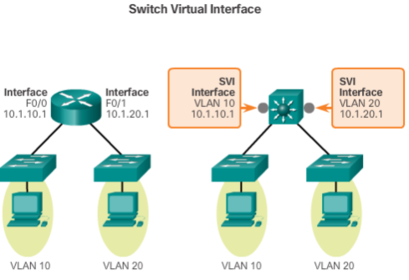
| Layer 3 switches usually have packet-switching throughputs in the millions of packets per second (pps), whereas traditional routers provide packet switching in the range of 100,000 pps to more than 1 million pps. All Catalyst multilayer switches support the following types of Layer 3 interfaces: 1. Routed port - A pure Layer 3 interface similar to a physical interface on a Cisco IOS router. | 2. Switch virtual interface (SVI) - A virtual VLAN interface for inter-VLAN routing. In other words, SVIs are the virtual-routed VLAN interfaces. High-performance switches, such as the Catalyst 6500 and Catalyst 4500, perform almost every function involving OSI Layer 3 and higher using hardware-based switching that is based on Cisco Express Forwarding |
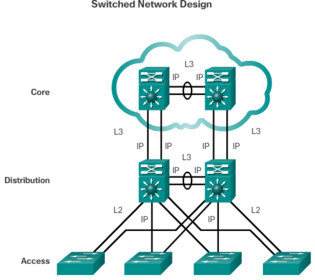
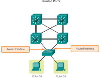
| Many users are in separate VLANs, and each VLAN is usually a separate subnet. Therefore, it is logical to configure the distribution switches as Layer 3 gateways for the users of each access switch VLAN. This implies that each distribution switch must have IP addresses matching each access switch VLAN. Layer 3 (routed) ports are normally implemented between the distribution and the core layer. | |
| The following are some of the reasons to configure SVI: * To provide a gateway for a VLAN so that traffic can be routed into or out of that VLAN * To provide Layer 3 IP connectivity to the switch * To support routing protocol and bridging configurations | |
| The following are some of the advantages of SVIs (the only disadvantage is that multilayer switches are more expensive): * It is much faster than router-on-a-stick, because everything is hardware switched and routed. | * No need for external links from the switch to the router for routing. * Not limited to one link. Layer 2 EtherChannels can be used between the switches to get more bandwidth. * Latency is much lower, because it does not need to leave the switch. |
| A routed port is a physical port that acts similarly to an interface on a router. Unlike an access port, a routed port is not associated with a particular VLAN. A routed port behaves like a regular router interface. Also, because Layer 2 functionality has been removed, Layer 2 protocols, such as STP, do not function on a routed interface. However, some protocols, such as LACP and EtherChannel, do function at Layer 3. Unlike Cisco IOS routers, routed ports on a Cisco IOS switch do not support subinterfaces. routed ports are mostly configured between switches in the core and distribution layer | |
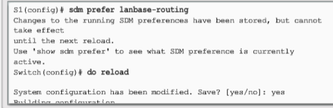
| The SDM template is changed to lanbase-routing. The switch must be reloaded for the new template to take effect. he lanbase-routing template is active on S1. With this template, static routing is supported for up to 750 static routes. | |
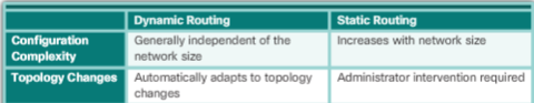
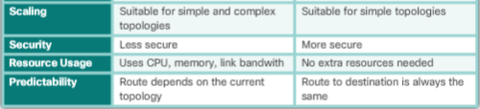
| Static routing provides some advantages over dynamic routing, including: 1. Static routes are not advertised over the network, resulting in better security. 2. Static routes use less bandwidth than dynamic routing protocols, no CPU cycles are used to calculate and communicate routes. 3. The path a static route uses to send data is known. | Static routing has the following disadvantages: 1. Initial configuration and maintenance is time-consuming. 2. Configuration is error-prone, especially in large networks. 3. Administrator intervention is required to maintain changing route information. 4. Does not scale well with growing networks; maintenance becomes cumbersome. 5. Requires complete knowledge of the whole network for proper implementation. |
| A default static route is a route that matches all packets. A default route identifies the gateway IP address to which the router sends all IP packets that it does not have a learned or static route. A default static route is simply a static route with 0.0.0.0/0 as the destination IPv4 address. Configuring a default static route creates a Gateway of Last Resort. | Default static routes are used: 1. When no other routes in the routing table match the packet destination IP address. In other words, when a more specific match does not exist. A common use is when connecting a company's edge router to the ISP network. 2. When a router has only one other router to which it is connected. This condition is known as a stub router. |
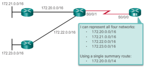
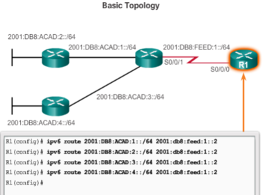
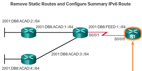
| Summary Static Route - To reduce the number of routing table entries, multiple static routes can be summarized into a single static route if: * The destination networks are contiguous and can be summarized into a single network address. * The multiple static routes all use the same exit interface or next-hop IP address. | |
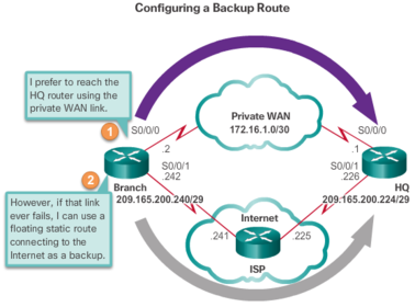
| Floating static routes are static routes that are used to provide a backup path to a primary static or dynamic route, in the event of a link failure. The floating static route is only used when the primary route is not available. To accomplish this, the floating static route is configured with a higher administrative distance than the primary route. Recall that the administrative distance represents the trustworthiness of a route. | |
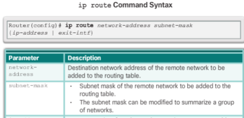
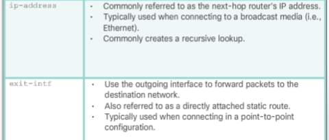
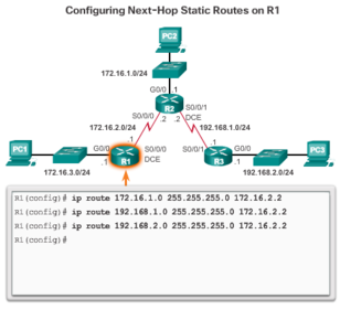
| "ip route (network-address subnet-mask {ip-address | exit-intf}) " The following parameters are required to configure static routing: * network-address - Destination network address of the remote network to be added to the routing table, often this is referred to as the prefix. | * subnet-mask - Subnet mask, or just mask, of the remote network to be added to the routing table. The subnet mask can be modified to summarize a group of networks. * ip-address - The IP address of the connecting router to use to forward the packet to the remote destination network. Commonly referred to as the next hop. * exit-intf - The outgoing interface to use to forward the packet to the next hop. |
| Before any packet is forwarded by a router, the routing table process must determine the exit interface to use to forward the packet. This is known as route resolvability. The route resolvability process will vary depending upon the type of forwarding mechanism being used by the router. CEF (Cisco Express Forwarding) is the default behavior on most platforms running IOS 12.0 or later. | |
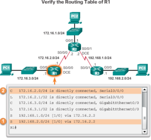
| When a packet is destined for the 192.168.2.0/24 network, R1: 1. Looks for a match in the routing table and finds that it has to forward the packets to the next-hop IPv4 address 172.16.2.2, as indicated by the label 1 in the figure. Every route that references only a next-hop IPv4 address and does not reference an exit interface must have the next-hop IPv4 address resolved using another route in the routing table with an exit interface. 2. R1 must now determine how to reach 172.16.2.2; therefore, it searches a second time for a 172.16.2.2 match. In this case, the IPv4 address matches the route for the directly connected network 172.16.2.0/24 with the exit interface Serial 0/0/0, as indicated by the label 2 in the figure. This lookup tells the routing table process that this packet is forwarded out of that interface. | |
| Note: CEF provides optimized lookup for efficient packet forwarding by using two main data structures stored in the data plane: a FIB (Forwarding Information Base), which is a copy of the routing table and an adjacency table that includes Layer 2 addressing information. | The information combined in both of these tables work together so there is no recursive lookup needed for next-hop IP address lookups. In other words, a static route using a next-hop IP requires only a single lookup when CEF is enabled on the router. |
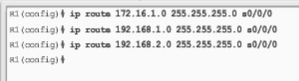
| Configuring a directly connected static route with an exit interface allows the routing table to resolve the exit interface in a single search, instead of two searches. Although the routing table entry indicates “directly connected”, the administrative distance of the static route is still 1. Only a directly connected interface can have an administrative distance of 0. | |
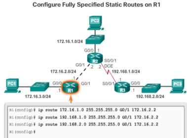
| In a fully specified static route, both the output interface and the next-hop IP address are specified Depending upon the topology and the configurations on other routers, this static route may or may not work. It is recommended that when the exit interface is an Ethernet network, that a fully specified static route is used including both the exit interface and the next-hop address. | |
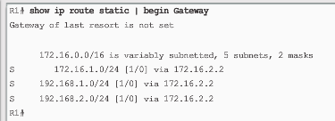
| Along with ping and traceroute, useful commands to verify static routes include: show ip route show ip route static show ip route "network" | |
| Default static routes are commonly used when connecting: * An edge router to a service provider network * A stub router (a router with only one upstream neighbor router) | ip route 0.0.0.0 0.0.0.0 { ip-address | exit-intf } 0.0.0.0 (Matches with any network address) 0.0.0.0 (Matches with any subnet mask) ip-address: * Commonly referred to as the next-hop router's IP address * Typically used when connecting to a broadcast media * Commonly creates a recursive lookup |
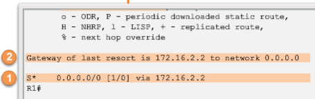
| In the figure, the show ip route static command output displays the contents of the routing table. Note the asterisk (*)next to the route with code ‘S’. As displayed in the Codes table in the figure, the asterisk indicates that this static route is a candidate default route, which is why it is selected as the Gateway of Last Resort. | |
| As with IPv4, before any packet is forwarded by the router, the routing table process must resolve the route to determine the exit interface to use to forward the packet. | |
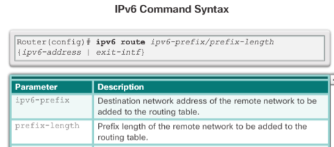
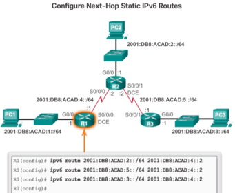
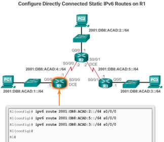
| When configuring a static route on point-to-point networks, an alternative to using the next-hop IPv6 address is to specify the exit interface. | |
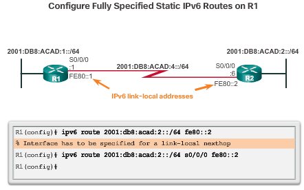
| Unlike IPv4, there is a situation in IPv6 when a fully specified static route must be used. If the IPv6 static route uses an IPv6 link-local address as the next-hop address, a fully specified static route including the exit interface must be used The reason a fully specified static route must be used is because IPv6 link-local addresses are not contained in the IPv6 routing table. Link-local addresses are only unique on a given link or network. The next-hop link-local address may be a valid address on multiple networks connected to the router. Therefore, it is necessary that the exit interface be included. | |
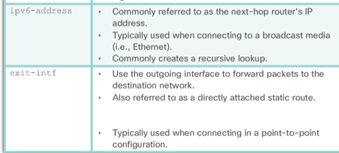
| Default Static IPv6 Route "ipv6 route ::/0 { ipv6-address | exit-intf }" ::/0 - Matches any IPV6 prefix regardless of prefix length ipv6-address: Commonly referred to as the next-hop router's IPv6 address Typically used when connecting to a broadcast media Commonly creates a recursive lookup | exit-intf: Use the outgoing interface to forward packets to the destination network Also referred to as a directly attached static route Typically used when connecting in a point-to-point configuration |
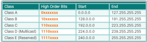
| Classful Network Addressing Class A - The 0.0.0.0 address is reserved for default routing and the 127.0.0.0 address is reserved for loopback testing. Class D Multicast addresses -- (RIP = 224.0.0.9, EIGRP = 224.0.0.10, OSPF 224.0.0.5, and 224.0.0.6). | |
| Using classful IP addresses meant that the subnet mask of a network address could be determined by the value of the first octet, or more accurately, the first three bits of the address. Routing protocols, such as RIPv1, only need to propagate the network address of known routes and do not need to include the subnet mask in the routing update. | This is due to the router receiving the routing update determining the subnet mask simply by examining the value of the first octet in the network address, or by applying its ingress interface mask for subnetted routes. The subnet mask was directly related to the network address |
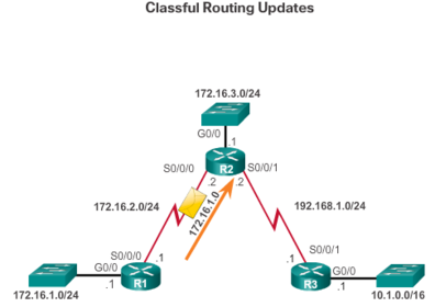
| R1 sends an update to R2. In the example, R1 knows that subnet 172.16.1.0 belongs to the same major classful network as the outgoing interface. Therefore, it sends a RIP update to R2 containing subnet 172.16.1.0. When R2 receives the update, it applies the receiving interface subnet mask (/24) to the update and adds 172.16.1.0 to the routing table | |
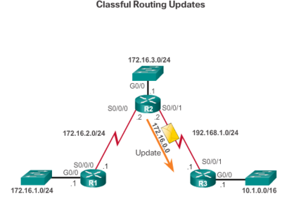
| R2 sends an update to R3. When sending updates to R3, R2 summarizes subnets 172.16.1.0/24, 172.16.2.0/24, and 172.16.3.0/24 into the major classful network 172.16.0.0. Because R3 does not have any subnets that belong to 172.16.0.0, it applies the classful mask for a class B network, which is /16. | |
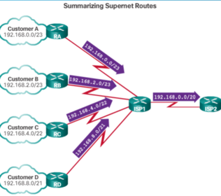
| Classless Inter-Domain Routing CIDR also reduces the size of routing tables and manages the IPv4 address space more efficiently using: * Supernetting - Occurs when the route summarization mask is a smaller value than the default traditional classful mask. | * Route summarization - Also known as prefix aggregation, routes are summarized into a single route to help reduce the size of routing tables. For instance, one summary static route can replace several specific static route statements |
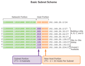
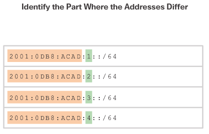
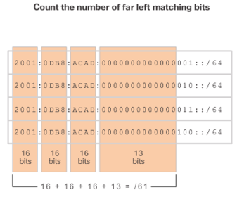
| Determining the summary route and subnet mask for a group of networks can be done in the following three steps: Step 1. List the networks in binary format. Step 2. Count the number of far left matching bits. This identifies the prefix length or subnet mask for the summarized route. Step 3. Copy the matching bits and then add zero bits to the rest of the address to determine the summarized network address. | |
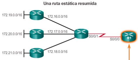
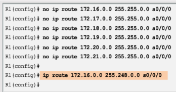
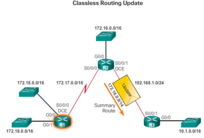
| Propagating VLSM and supernet routes requires a classless routing protocol such as RIPv2, OSPF, or EIGRP. Classless routing protocols advertise network addresses with their associated subnet masks. With a classless routing protocol, R2 can summarize networks 172.16.0.0/16, 172.17.0.0/16, 172.18.0.0/16, and 172.19.0.0/16, and advertise a supernet summary static route 172.16.0.0/14 to R3. R3 then installs the supernet route 172.16.0.0/14 in its routing table. Note: When a supernet route is in a routing table, for example, as a static route, a classful routing protocol does not include that route in its updates. | |
| With fixed-length subnet masking (FLSM), the same number of addresses is allocated for each subnet. If all the subnets have the same requirements for the number of hosts, these fixed size address blocks would be sufficient. However, most often that is not the case. Note: FLSM is also referred to as traditional subnetting. | |
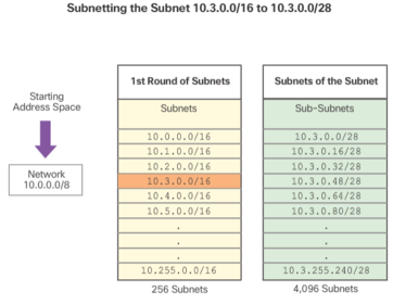
| In Figure 4, the 10.3.0.0/16 subnet is further subnetted with a /28 mask, thus creating 4,096 subnets and allowing 14 host addresses per subnet. The subnets ranging from 10.3.0.0/28 to 10.3.255.240/28 are subnets of the subnet 10.3.0.0/16. | |
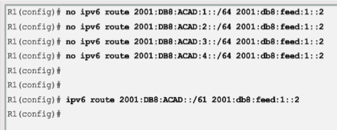
| Multiple static IPv6 routes can be summarized into a single static IPv6 route if: The destination networks are contiguous and can be summarized into a single network address. The multiple static routes all use the same exit interface or next-hop IPv6 address | |
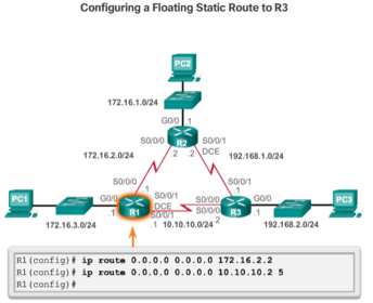
| R1 is configured with a default static route pointing to R2. Because no administrative distance is configured, the default value (1) is used for this static route. R1 is also configured with a floating static default pointing to R3 with an administrative distance of 5. This value is greater than the default value of 1 and, therefore, this route floats and is not present in the routing table, unless the preferred route fails. | |
Want to create your own Flashcards for free with GoConqr? Learn more.