6451328
Description
Flashcards by John Dedios, updated more than 1 year ago
|
|
Created by John Dedios
over 7 years ago
|
|
| Question | Answer |
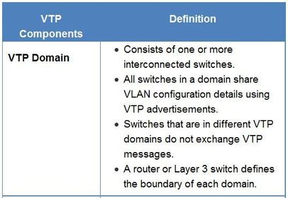
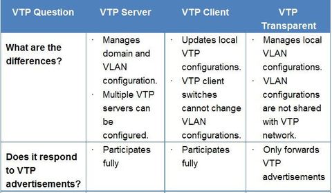
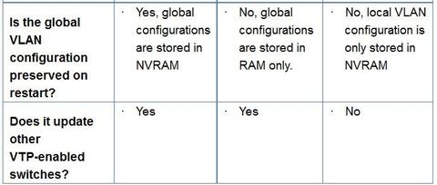
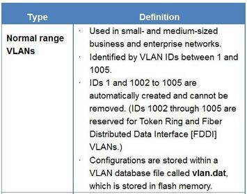
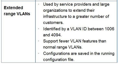
| VTP Overview VLAN trunking protocol (VTP) allows a network administrator to manage VLANs on a switch configured as a VTP server. The VTP server distributes and synchronizes VLAN information over trunk links to VTP-enabled switches throughout the switched network. This minimizes the problems caused by incorrect configurations and configuration inconsistencies. | Note: VTP only learns about normal-range VLANs (VLAN IDs 1 to 1005). Extended-range VLANs (IDs greater than 1005) are not supported by VTP version 1 or version 2. VTP version 3 does support extended VLANs Note: VTP stores VLAN configurations in a database called vlan.dat. |
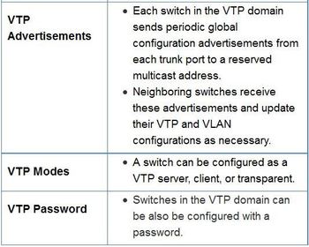
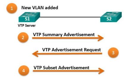
| VTP Advertisements - Summary advertisements – These inform adjacent switches of VTP domain name and configuration revision number. - Advertisement request – These are in response to a summary advertisement message when the summary advertisement contains a higher configuration revision number than the current value. - Subset advertisements – These contain VLAN information including any changes. | * By default, Cisco switches issue summary advertisements every five minutes. * The configuration revision number is a 32-bit number that indicates the level of revision for a VTP packet Each time that you make a VLAN change in a VTP device, the configuration revision is incremented by one. ** Note: To reset a configuration revision on a switch, change the VTP domain name, and then change the name back to the original name. |
| VTP Advertisements When the switch receives a summary advertisement packet, the switch compares the VTP domain name to its own VTP domain name. If the name is different, the switch simply ignores the packet. If the name is the same, the switch then compares the configuration revision to its own revision. If its own configuration revision number is higher or equal to the packet's configuration revision number, the packet is ignored. If its own configuration revision number is lower, an advertisement request is sent asking for the subset advertisement message. | |
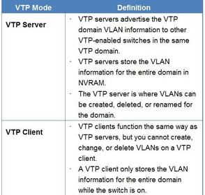
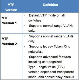
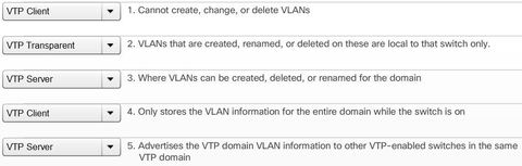
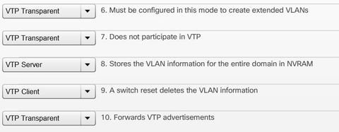
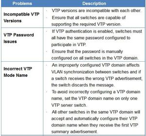
| VTP Versions ** Switches in the same VTP domain must use the same VTP version. Note: VTPv2 is not much different than VTPv1 and is generally only configured if legacy Token Ring support is required. The newest version of VTP is Version 3. * By default, the VTP domain name is NULL * By default, a switch is in VTP server mode. | |
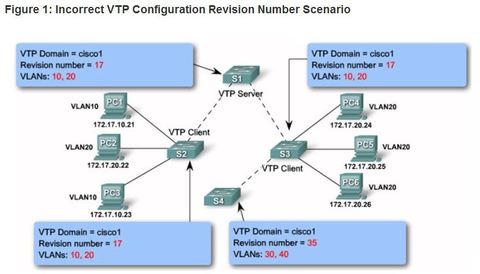
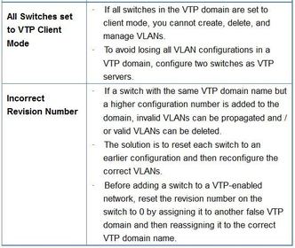
| VTP Caveats Some network administrators avoid VTP because it could potentially introduce false VLAN information into the existing VTP domain. ** The configuration revision number is used when determining whether a switch should keep its existing VLAN database, or overwrite it with the VTP update sent by another switch in the same domain with the same password. | ** Adding a VTP-enabled switch to an existing VTP domain will wipe out the existing VLAN configurations in the domain if the new switch is configured with different VLANs and has a higher configuration revision number than the existing VTP server. ** The new switch can be either a VTP server or client switch. This propagation can be difficult to correct. Therefore, when a switch is added to a network, ensure that it has a default VTP configuration. |
| VTP Caveats Ej: S4 has VLAN 1 and is configured with VLAN 30 and 40. But it does not have VLANs 10 and 20 in its database. Unfortunately, because S4 has a higher revision number, the rest of the switches in the domain will sync to S4’s revision. The consequence is that VLANs 10 and 20 will no longer exist on the switches, leaving clients that are connected to ports belonging to non-existing VLANs without connectivity. | |
| VTP Caveats The VTP configuration revision number is stored in NVRAM (or Flash on some platforms) and is not reset if you erase switch configuration and reload it. To reset VTP configuration revision number to zero you have two options: | * Change the switch's VTP domain to a nonexistent VTP domain and then change the domain back to the original name. * Change the switch's VTP mode to transparent and then back to previous VTP mode. |
| Steps to configure VTP: Step 1: Configure the VTP Server Step 2: Configure the VTP Domain Name and Password | Step 3: Configure the VTP Clients Step 4: Configure VLANs on the VTP Server Step 5: Verify the VTP Clients Have Received the New VLAN Information |
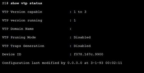
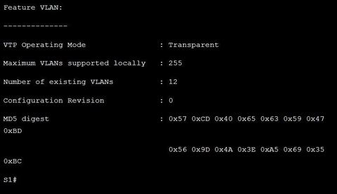
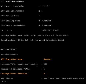
| Step 1 - Configure the VTP Server " vtp mode server" Ej: ? command to confirm that S1 is a VTP server Notice how the configuration revision number is still set to 0 and the number of existing VLANs is 5. This is because no VLANs have yet been configured and the switch does not belong to a VTP domain. The 5 VLANs are the default VLAN 1 and VLANs 1002-1005. | |
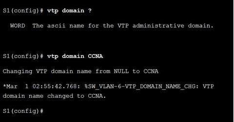
| Step 2 - Configure the VTP Domain Name and Password Ej: The domain name is configured using the xxx global configuration command. ** S1 will then send out a VTP advertisement to S2 and S3. If S2 and S3 have the default configuration with the NULL domain name, then both switches will accept CCNA as the new VTP domain name. "vtp password (password) " "show vtp password " | |
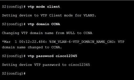
| Step 3 - Configure the VTP Clients Ej: ? Configure S2 and S3 as VTP clients in the CCNA domain using the VTP password cisco12345. A VTP client must have the same domain name as the VTP server before it will accept VTP advertisements. | |
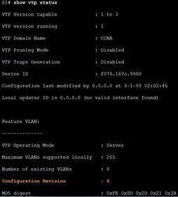
| Step 4 - Configure VLANs on the VTP Server Ej: ? Verify the VTP Status after VLANs are Configured on the VTP Server "show vlan brief" Notice that the configuration revision number incremented six times from the default 0 to 6. This is because three new, named VLANs were added. Each time the administrator makes a change to the VTP server’s VLAN database, this number will increase by one. The number increased by one when the VLAN was added and by one when the name for the VLAN was configured. | |
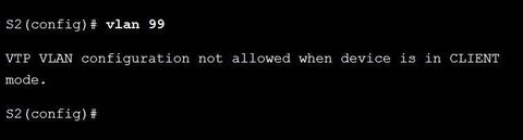
| Step 5 - Verify that the VTP Clients Have Received the New VLAN Information "show vlan brief" "show vtp status" Ej: ? Because S2 is operating in VTP client mode, attempts to configure VLANs will not be allowed | |
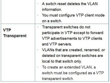
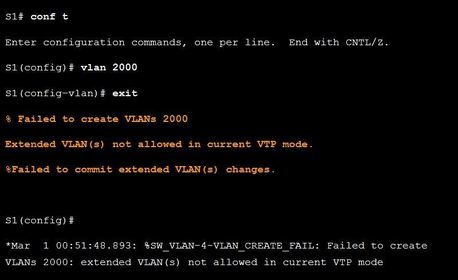
| Normal and Extended VLANs Note: A Cisco Catalyst 2960 switch can support up to 255 normal range and extended range VLANs Ej: by default, a Catalyst 2960 Plus Switch does not support extended VLANs. If an extended VLAN is required, then the switch must be configured as a VTP transparent device | |
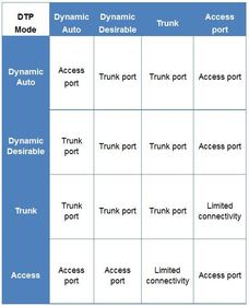
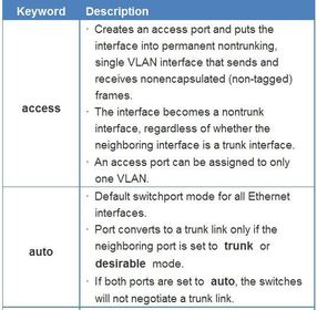
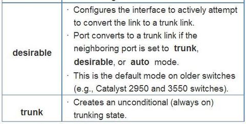
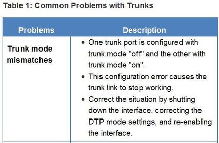
| DTP Trunking Modes ** Dynamic Trunking Protocol (DTP) helps switches negotiate and establish 802.1Q trunk links. DTP is a Cisco proprietary protocol. The trunking mode defines how the port negotiates using DTP to set up a trunk link with its peer port "switchport mode {access | dynamic {auto | desirable} | trunk} " "switchport nonnegotiate" | |
| Deleting VLANs "no vlan (vlan-id)" When you delete a VLAN, any ports assigned to that VLAN become inactive. They remain associated with the VLAN (and thus inactive) until you assign them to a new VLAN. | Notice how interfaces Fa0/18 through 0/24 are no longer listed in the VLAN assignments. ** Any ports that are not moved to an active VLAN are unable to communicate with other stations after deleting the VLAN. Therefore, before deleting a VLAN, reassign all member ports to a different VLAN. |
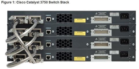
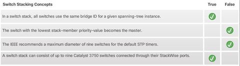
| Switch Stacking Concepts ** A switch stack can consist of up to nine Catalyst 3750 switches connected through their StackWise ports. One of the switches controls the operation of the stack and is called the stack master. ** The stack master and the other switches in the stack are stack members. Layer 2 and Layer 3 protocols present the entire switch stack as a single entity to the network. | |
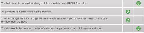
| Switch Stacking Concepts ** Every member is uniquely identified by its own stack member number. All members are eligible masters. If the master becomes unavailable, there is an automatic process to elect a new master from the remaining stack members. One of the factors is the stack member priority value. The switch with the highest stack-member priority-value becomes the master. | ** One of the primary benefits of switch stacks is that you manage the stack through a single IP address. The IP address is a system-level setting and is not specific to the master or to any other member. You can manage the stack through the same IP address even if you remove the master or any other member from the stack. |
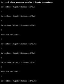
| Switch Stacking Concepts ** The master contains the saved and running configuration files for the stack. Therefore, there is only one configuration file to manage and maintain. The configuration files include the system-level settings for the stack and the interface-level settings for each member. Each member has a current copy of these files for backup purposes. ** Ej: shows the interfaces on a switch stack with four 52-port switches. Notice the first number after the interface-type is the stack-member number. | |
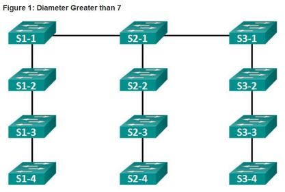
| Spanning Tree and Switch Stacks ** Another benefit to switch stacking is the ability to add more switches to a single STP instance without increasing the STP diameter. The diameter is the maximum number of switches that you must cross to link any two switches. ** The IEEE recommends a maximum diameter of seven switches for the default STP timers. For example, in Figure the diameter from S1-4 to S3-4 is nine switches. This design violates the IEEE recommendation. | |
| Spanning Tree and Switch Stacks The recommended diameter is based on default STP timer values, which are as follows: 1. Hello Timer (2 seconds) - The interval between BPDU updates. | 2. Max Age Timer (20 seconds) - The maximum length of time a switch saves BPDU information. 3. Forward Delay Timer (15 seconds) - The time spend in the listening and learning states. |
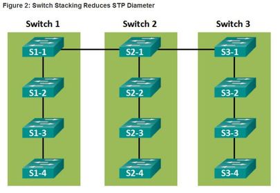
| Spanning Tree and Switch Stacks ** Switch stacks help to maintain or reduce the impact of diameter on STP reconvergence. In a switch stack, all switches use the same bridge ID for a given spanning-tree instance. Ej: This means that, if the switches in Figure 1 are stacked, as shown in Figure 2, then the maximum diameter becomes 3 instead of 9. | |
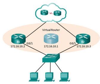
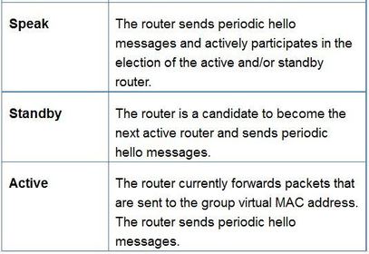
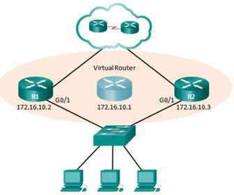
| Hot Standby Router Protocol (HSRP) was designed by Cisco to allow for gateway redundancy without any additional configuration on end devices. Routers configured with HSRP work together to present themselves as a single virtual default gateway (router) to end devices One of the routers is selected by HSRP to be the active router. The active router will act as the default gateway for end devices. The other router will become the standby router. If the active router fails, the standby router will automatically assume the role of the active router. It will assume the role of default gateway for end devices | |
| Hot Standby Router Protocol (HSRP) Both the HSRP active router and the standby router present a single default gateway address to end devices. The default gateway address is a virtual IP address along with a virtual MAC address that is shared amongst both HSRP routers. End devices use this virtual IP address as their default gateway address. The HSRP virtual IP address is configured by the network administrator. The virtual MAC address is created automatically. Regardless of which physical router is used, the virtual IP and MAC addresses provide consistent default gateway addressing for the end devices. | |
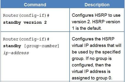
| HSRP Versions The default version for Cisco IOS 15 is version 1. HSRP version 2 provides the following enhancements: - HSRPv2 expands the number of supported groups. HSRP version 1 supports group numbers from 0 to 255. HSRP version 2 supports group numbers from 0 to 4095. - HSRPv1 uses the multicast address of 224.0.0.2. HSRP version 2 uses the IPv4 multicast address 224.0.0.102 or the IPv6 multicast address FF02::66 to send hello packets. | * HSRPv1 uses the virtual MAC address range 0000.0C07.AC00 to 0000.0C07.ACFF, where the last two hexadecimal digits indicate the HSRP group number. HSRP v2 uses the MAC address range from 0000.0C9F.F000 to 0000.0C9F.FFFF for IPv4 and 0005.73A0.0000 through 0005.73A0.0FFF for IPv6 addresses. For both IPv4 and IPv6, the last three hexadecimal digits in the MAC address indicate the HSRP group number. - HSRPv2 adds support for MD5 authentication Note: Group numbers are used for more advanced HSRP configurations that are beyond the scope of this course. For our purposes, we will use group number 1. |
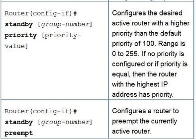
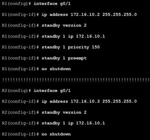
| HSRP Priority and Preemption The role of the active and standby routers is determined during the HSRP election process. ** By default, the router with the numerically highest IP address is elected as the active router. | ** HSRP priority - can be used to determine the active router. The router with the highest HSRP priority will become the active router. By default, the HSRP priority is 100. If the priorities are equal, the router with the numerically highest IP address is elected as the active router. To configure a router to be the active router, use the standby priority interface command. The range of the HSRP priority is 0 to 255. |
| HSRP Preemption ** By default, after a router becomes the active router, it will remain the active router even if another router comes online with a higher HSRP priority. ** To force a new HSRP election process, preemption must be enabled using the "standby preempt" interface command. Preemption is the ability of an HSRP router to trigger the re-election process. | With preemption enabled, a router that comes online with a higher HSRP priority will assume the role of the active router. ** Preemption only allows a router to become active router if it has a higher priority. A router enabled for preemption, with equal priority but a higher IP address will not preempt an active router Note: With preemption disabled, the router that boots up first will become the active router if there are no other routers online during the election process. |
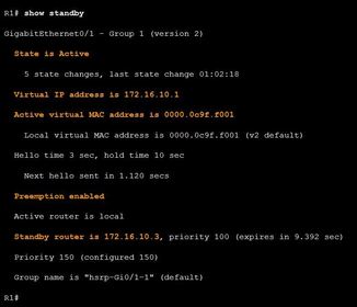
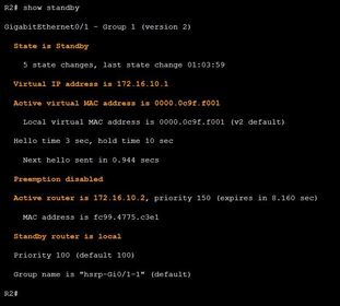
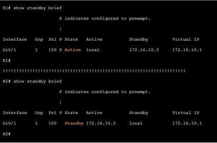
| HSRP Verification Note: You can change the default group name with the "standby [group-number] name (group-name)" interface configuration command. "show standby" Ej: "show standby brief" | |
| HSRP Failure Most issues will arise during one of the following HSRP functions: 1. Failing to successfully elect the active router that controls the virtual IP for the group. 2. Failure of the standby router to successfully keep track of the active router. | 3. Failing to determine when control of the virtual IP for the group should be handed over to another router. 4. Failure of end devices to successfully configure the virtual IP address as the default gateway. |
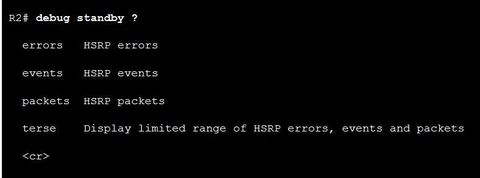
| HSRP Debug Commands Ej: ? The available HSRP debug commands can be viewed by entering the xxx command Use debug standby packets to view the receiving and sending of hello packets every 3 seconds HSRP routers monitor these hello packets and will initiate a state change after 10 seconds if no hellos are heard from an HSRP neighbor. | |
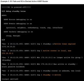
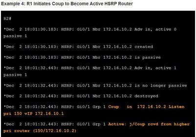
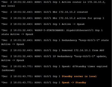
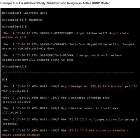
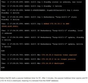
| HSRP Debug Commands ** HSRP behaves differently, depending on whether the active router fails or is manually shutdown by the administrator. Ej: ? to view the HSRP events as R1 is powered down and R2 assumes the role of active HSRP router for the 172.16.10.0/24 network. | |
| Common HSRP Configuration Issues * The HSRP routers are not connected to the same network segment. Although this could be a physical layer issue, it could also be a VLAN subinterface configuration issue. * The HSRP routers are not configured with IP addresses from the same subnet. HSRP hello packets are local. They are not routed beyond the network segment. Therefore, a standby router would not know when the active router fails. | * The HSRP routers are not configured with the same virtual IP address. The virtual IP address is the default gateway for end devices. ** The HSRP routers are not configured with the same HSRP group number. This will cause each router to assume the active role. * End devices are not configured with the correct default gateway address. Although not directly related to HSRP, configuring the DHCP server with one of the HSRP router’s real IP addresses would mean that end devices would only have connectivity to remote networks when that HSRP router is active. |
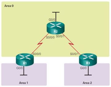
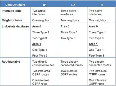
| Multiarea OSPF Data Structures OSPF stores routing information in four main data structures: 1. Interface table - This table includes a list of all active interfaces that have been enabled for OSPF. Type 1 LSAs include the subnets associated with each active interface. 2. Neighbor table - This table is used to manage neighbor adjacencies through hello timers and dead timers. Neighbor entries are added and refreshed when a hello is received. Neighbors are removed when the dead timer expires. | ** 3. Link-state database - This is the primary data structure used by OSPF to store network topology information. It includes full topological information about each area that the OSPF router is connected to, as well as any paths that are available to reach other networks or autonomous systems. 4. Routing table - After the SPF algorithm is calculated, the best routes to each network are offered to the routing table. |
| Remove only VLAN 100 - To remove all VLANs from a switch: "delete flash:vlan.dat" - To change the assigned VLAN for an interface: "no switchport access vlan 100" | * To remove VLAN 100 as an allowed VLAN on a trunk: "no switchport trunk allowed vlan 100" but this would not remove the VLAN from the switch. To delete a single VLAN: "no vlan 100" |
Want to create your own Flashcards for free with GoConqr? Learn more.