890129
Description
Mind Map by Julia Smith, updated more than 1 year ago
|
|
Created by Julia Smith
over 11 years ago
|
|
CEG2301
- Basics
- Structural elements
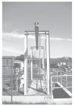
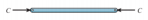
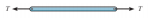
- Tie rod
- Tensile forces
- Slender
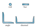
- Common cross
sections >>
- Tensile forces
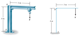
- Beam
- Straight
horizontal
members
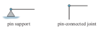
- <<Support
types
- <<Support
types
- Vertical loading
- ^^Most effcient^^
cross section
- Straight
horizontal
members
- Colums
- Vertical
members
- Resist axial
compression
- Vertical
members
- Tie rod
- Types of structure
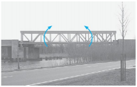
- ^^Truss^^
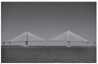
- Cable^^
- ^^Arch^^
- Frame>>
- <<
Surface
structure
- ^^Truss^^
- Loads
- Dead loads
Annotations:
- Wieght of the structure and premenent objects
- Live loads
Annotations:
- natural forces , moving loads and tempoary objects
- Wind loads
- Accidental
loads
Annotations:
- Earthquakes and other desasters
- Dead loads
- Structural elements
- Idealization
- Structures^^
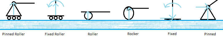
- Connections
- Pinned>>
- Torsion>>
- K= spring
constant
- K= spring
constant
- Fixed>>
- Reactions>>
- Pinned>>
- Principle of Superposition
Annotations:
- Summing all forces and find the eqivelent force required for the same effects
- material must behave in a liner elastic manner and the geometry of the structure must not change significantly
- The total displacement or internal loadings (stress) at a point in a
structure subjected to several external loadings can be determined
by adding together the displacements or internal loadings (stress)
caused by each of the external loads acting separately.
- Diagram of idea
- Diagram of idea
- Structures^^
- Equations
- Equilibrium
equations
Annotations:
- 6 total 3 moments in x y and z and 3 forces in x y and z
- (sum)Fo=0
- Forces in each
direction much be 0
- Forces in each
direction much be 0
- (sum)Mo=0
- Moments in each
direction must be 0
- Moments in each
direction must be 0
- Determinacy
- r=3n
- n=parts r=reactions
- r=3n
- Stability
- r<3n
- Unstable
- Unstable
- r>3n
- Unstable if reactions are concurent or parellell or
components form a collapseble mechanisium
- Unstable if reactions are concurent or parellell or
components form a collapseble mechanisium
- r<3n
- Equilibrium
equations
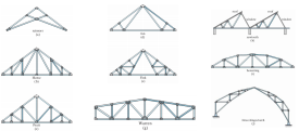
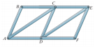
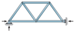
- Statically determinate trusses
- A truss is a structure comprised
of slender members joined
together at there end points
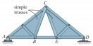
- ^^Compound truss^^
- ^^Simple truss^^
- ^^Compound truss^^
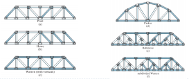
- Common
uses
- <<Roofing
- Bridges>>
- <<Roofing
- Assumptions
- The members are joined by
smooth pins and members
are conccurent at a point
- All loading as applied at the joints
- All members act with axial force
- ^^Compression ^^
- ^^Tension ^^
- ^^Compression ^^
- The members are joined by
smooth pins and members
are conccurent at a point
- Determinacy
- (b+r=2j)=determenent
- (b+r>2j)=indeterminate
- Degree of
indeterminacy =
(b+r)=2j
- j=joints r=external
reactions
b=number of bars
- j=joints r=external
reactions
b=number of bars
- (b+r=2j)=determenent
- Stability
- (b+r)<2j = internally
unstable
- Will collapse as
there are not
enough bars or
reactions to
constrain the joints
- Will collapse as
there are not
enough bars or
reactions to
constrain the joints
- Externally unstable
- ^^Parallel external
forces^^
- ^^Conccurent
external forces^^
- ^^Parallel external
forces^^
- (b+r)<2j = internally
unstable
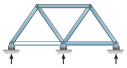
- Method of joints
- Methord
- separate each joint out of the frame
and draw in arows to show the forces
that use trig to resolve forces to keep
the point in eqilibrium repeat for each
joint until all required forces are found
keep sign convention consistant for all
forces and signs will work out
- separate each joint out of the frame
and draw in arows to show the forces
that use trig to resolve forces to keep
the point in eqilibrium repeat for each
joint until all required forces are found
keep sign convention consistant for all
forces and signs will work out
- Other notes
- Assume truss is in equilibrium
- Assume all unknown forces to
be in tension or compression for
signs to work out
- Some members can be
zero and carry no force but
are required for stability
- Assume truss is in equilibrium
- Methord
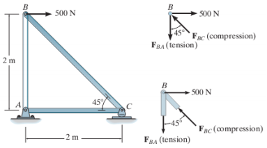
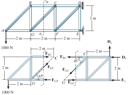
- Method of sections
- Metord
- Cut the truss through the required members
and treat each part as a separate objects in
equilibrium treating the cut member forces
as external forces apply the equilibrium
equations to find the forces required
- <<Example diagram to draw
- Cut the truss through the required members
and treat each part as a separate objects in
equilibrium treating the cut member forces
as external forces apply the equilibrium
equations to find the forces required
- Assume forces
and stick to the
sign convention
- Metord
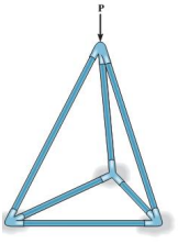
- Space trusses (3-D)
- Equations
- b+r<3j =
Unstable
truss
- b+r=3j = Statistically
determinate - Check stability
- b+r>3j = Statically
indeterminate - Check stability
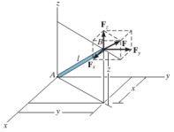
- ^^Force
Components^^
- l=Sqrt(x^2+y^2+z^2)
- Fx=F(X/l)
- Fy=F(y/l)
- Fz=F(z/l)
- F=Sqrt(Fx^2+Fy^2+Fz^2)
- l=Sqrt(x^2+y^2+z^2)
- b+r<3j =
Unstable
truss
- Equations
- A truss is a structure comprised
of slender members joined
together at there end points
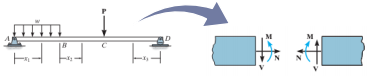
- Internal
loading
- Befoe a structural member can be
proportioned the forces and moments in each
member need to be known
- This can be
done at any
point using
the method
of sections
- This can be
done at any
point using
the method
of sections
- Coplanar structure
internal loading
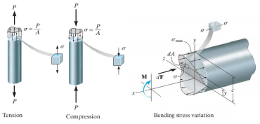
- Loads represent stress over a cross sectional area>>>>
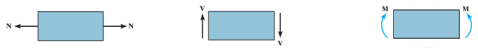
- Sign
conventions
- Normal force , N
- + Force =
elongation
of
segment
- + Force =
elongation
of
segment
- Shear force, v
- + Shear = rotates
the segments
clock wise
- + Shear = rotates
the segments
clock wise
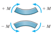
- Bending moment, M
- + Bending =
bends the
segments
upwards
(concave
shape)
- + Bending =
bends the
segments
upwards
(concave
shape)
- Normal force , N
- Loads represent stress over a cross sectional area>>>>
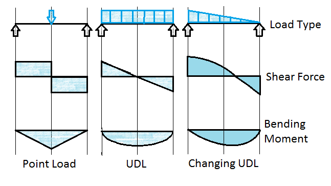
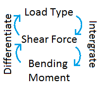
- Diagrams
- (dV/dx) = W(x)
- Slope of the shear diagram is equal to the intensity of the distributed load
- Slope of the shear diagram is equal to the intensity of the distributed load
- (dM/dx) = V
- Slope of moment diagram is equal to the intensity of the shear
- Slope of moment diagram is equal to the intensity of the shear
- (delta)V = Inter(
W(x) dx)
- Change in shear over a length is equal to the area under the loading
diagram
- Change in shear over a length is equal to the area under the loading
diagram
- (delta)M = Inter(
W(x) dx)
- Change in bending moment over a length is equal to the area under the
shear diagram
- Change in bending moment over a length is equal to the area under the
shear diagram
- (dV/dx) = W(x)
- Shapes>>
- Befoe a structural member can be
proportioned the forces and moments in each
member need to be known
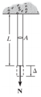
- Deflections
- Causes
- Loads
- Tempreture
- Fabrication
errors
- Settlement
- Loads
- Deflections need to be limited to avoid
breaking connected brittle materials
- Beam deflection mainly from
internal bending
- Truss deflections mainly from internal axial forces
- Beam deflection mainly from
internal bending
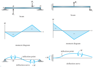
- Deflection diagrams
- Positive moment = Upward bend
Negative moment = Downward bend
- If the shape of the moment diagram is known an
elastic curve can be constructed and visa versa
- << Example
diagrams
- << Example
diagrams
- Positive moment = Upward bend
Negative moment = Downward bend
- Causes
- Principle of conservation of energy
- External work
- Force
- dUe = F dx
- Force applied gradually
- Ue = 0.5 P (delta)
- Ue = 0.5 P (delta)
- Force already applyed
- Ue' = P (delta)'
- Ue' = P (delta)'
- Force applied gradually
- dUe = F dx
- Moment
- dUe = M d(theta)
- Force applied
gradually
- Ue + 0.5 M (theta)
- Ue + 0.5 M (theta)
- Moments
already applied
- Ue' = M (theta)'
- Ue' = M (theta)'
- Force applied
gradually
- dUe = M d(theta)
- Force
- Strain energy
- Axial force
- Ui = (N^2L)/(2AE)
- Work done
gradually will be
converted to
strain energy and
stored in the bar
- Work done
gradually will be
converted to
strain energy and
stored in the bar
- Ui = (N^2L)/(2AE)
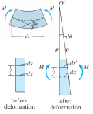
- Bending
- Ui = Inter(o->L)
((M^2dx)/(2EI))
- Load applied gradually
causes a moment
leading to a rotation
- Load applied gradually
causes a moment
leading to a rotation
- Ui = Inter(o->L)
((M^2dx)/(2EI))
- Axial force
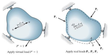
- Principle of
virtual work
- External virtual work
- 1.(delta)
- 1.(delta)
- Internal virtual work
- u.dL
- u.dL
- First apply virtual load to
find real displacement by
proportions
- Works for loads
and moments,
beams and
trusses.
- Loads
- 1.(delta)=Sum(u.dL)
- 1.(delta)=Sum(u.dL)
- Moments
- 1.(theta)=Sum(u(theta).dL)
- 1.(theta)=Sum(u(theta).dL)
- Trusses
- 1.(delta)=Sum((nNL)/(AE))
- Use a table with
columns for:
member, n, N, L, nNL.
For each member
work out the values
sum the nNL column
and devide by the A
and E values whith
should be given
- Use a table with
columns for:
member, n, N, L, nNL.
For each member
work out the values
sum the nNL column
and devide by the A
and E values whith
should be given
- 1.(delta)=Sum((nNL)/(AE))
- Beams
- Forces
- 1.(delta)=Inter(0->L)(mM/EI)dx
- 1.(delta)=Inter(0->L)(mM/EI)dx
- Moments
- 1.(theta)=Inter(0->L)(m(theta)M/EI)dx
- 1.(theta)=Inter(0->L)(m(theta)M/EI)dx
- Tables can be used for
Inter(0->L)(m(x)m'(x)dx)
when the shapes are
known
- Forces
- Loads
- Works for loads
and moments,
beams and
trusses.
- External virtual work
- Castigliano's
Theorem
- The external work is a function of
external loads and if the force is
increased by a differential amount
the new strain also increases and
the increase is not effected by the
order of the applied loads
- (delta)j = (lDelta)Ui/(ldelta)Pj)
- So for a truss
- (delta) =
Sum(N((ldelta)N/(ldelta)P)(L/AE))
- Use a table with columns: member, N,
(ldelta)N/(ldelta)P, N(P=0), L and
N((ldelta)N/(ldelta)P)L. Work out the
values for each column for each
member and then sum the final column
and devide by the given A and E values
- Use a table with columns: member, N,
(ldelta)N/(ldelta)P, N(P=0), L and
N((ldelta)N/(ldelta)P)L. Work out the
values for each column for each
member and then sum the final column
and devide by the given A and E values
- (delta) =
Sum(N((ldelta)N/(ldelta)P)(L/AE))
- So for a truss
- (delta)j = (lDelta)Ui/(ldelta)Pj)
- The external work is a function of
external loads and if the force is
increased by a differential amount
the new strain also increases and
the increase is not effected by the
order of the applied loads
- External work
- Statically
indeterminent
- When the number of unknown reactions
or internal forces exceeds the number of
equilibrium equations avalable
- Advantages
- Maximum stress and deflection is genrally
smallered than statically determinate structures
- Tendency to redistribute loads to redundant
supports when there is fault or overloading
- Maximum stress and deflection is genrally
smallered than statically determinate structures
- Disadvantages
- Redundant supports can cause differential displacements
that introduce internal stress to the structure
- Redundant supports can cause differential displacements
that introduce internal stress to the structure
- Methods of
analysis
- Factors
to satisfy
- Equilibrium
- Reactive forces hold the structure at rest
- Reactive forces hold the structure at rest
- Compatibility
- Segments in the structure fit
together with out breaks or overlaps
- Segments in the structure fit
together with out breaks or overlaps
- Force-displacement
- depends on material
response (linear elastic)
- depends on material
response (linear elastic)
- Equilibrium
- Force
method
- Writing equations that satisfy the
compatibility and force-displacement
requirements in order to determine
the redundant forces
- Writing equations that satisfy the
compatibility and force-displacement
requirements in order to determine
the redundant forces
- Displacement
method
- Analysis based on first writeing
force-displacement relations then
satisfying the equilibrium requirements
- Displacements
unknown
- reactions can be determended from the
compatibility equations and
force-displacements equations
- reactions can be determended from the
compatibility equations and
force-displacements equations
- Analysis based on first writeing
force-displacement relations then
satisfying the equilibrium requirements
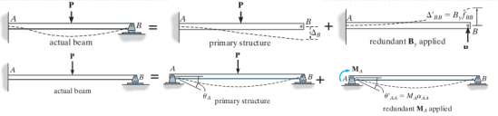
- Force method
Details
- Compatibility
equations
- Moments
- 0=(theta)A+
MA(alpha)AA
- MA=-(theta)A/(alpha)AA
- (alpha)AA=
angular
flexibility
coeffcient
- the angular
displacement at A
caused by a unit
couple moment at A
- the angular
displacement at A
caused by a unit
couple moment at A
- (alpha)AA=
angular
flexibility
coeffcient
- MA=-(theta)A/(alpha)AA
- 0=(theta)A+
MA(alpha)AA
- Forces
- 0= -(delta)B
+(delta)'BB
- (delta)'BB=ByFBB
- By=(delta)B/FBB
- FBB= Linear
flexibility coefficient
- The
displacement
at B caused by
a unit load
acting in the
direction of By
- The
displacement
at B caused by
a unit load
acting in the
direction of By
- FBB= Linear
flexibility coefficient
- By=(delta)B/FBB
- (delta)'BB=ByFBB
- 0= -(delta)B
+(delta)'BB
- << Visual representation of equations and methord
- Moments
- Compatibility
equations
- Factors
to satisfy
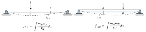
- Maxwell's
theorem -
Betti's law
- The displacement and rotation at
point B on a structure due to a unit
load acting on it at point A is the
same as the displacement and
rotation of point A when the unit
load is applied to point B
- ^^FAB = FBA^^
- ^^FAB = FBA^^
- The displacement and rotation at
point B on a structure due to a unit
load acting on it at point A is the
same as the displacement and
rotation of point A when the unit
load is applied to point B
- When the number of unknown reactions
or internal forces exceeds the number of
equilibrium equations avalable
Media attachments
Want to create your own Mind Maps for free with GoConqr? Learn more.