Description

Page 1
The Physical LayerAs you've seen from my last set of notes, the Physical Layer is the foundation on which a computer network is built. The properties of different kinds of physical channels determines the performance, such as throughput, latency, error rate etc. In network communication, everything goes over the Physical Layer. It involves the actual physical medium and is used in the most basic network layers and is the most basic network layer. The actual signal that is used varies depending on types of medium; electrical modulation, radio waves and optical signals. In theory, any medium can be used; RFC 1149. It is responsible for a number of services, such as: Bit-by-bit delivery Providing a standardised interface to the medium Modulation Line coding Flow Control Multiplexing Circuit Switching Forward Error Recovery Carrier Sense And many more.
Page 2
Guided Transmission MediaWe need to understand and appreciate there are differing media types available to us. Physical and Wireless Media is required to transfer signals from one place to another and to impose a structure. Often by the structure, the media places upon the designer and installer of a network.In terms of data, although a given media is used as the transfer agent, it is the Media Protocol that defines the process and characteristics of the data transfer. In other other words; some media types can be used to support multiple Media Protocols.Moving back to the structure, we already know that physical media can impose a structure. But that structure is called a topology, remember star, ring, bus and mesh topologies? It is that structure and the Media Protocol that defines the limitations and expectations of a network in terms of; the number of nodes that can operate within the network, the distance over which the network will operate and the bandwidth that the network can support.
Page 3
Bandwidth Bandwidth is simply a measure of the amount of data that can be sent over a network connection. It indicates the maximum transmission capacity. If you imagine a water hose - the water flowing through the hose is the data, and the diameter of the hose is the bandwidth. The bigger the diameter, the more water can flow through at any one time. Bandwidth might be incorrectly referred to as the amount of data transmitted. This is the data transfer, and in the water-hose metaphor, it would be the total volume of water that went through the hose.
Page 4
BroadbandA broadband connection is one that allows data to be on multiple channels simultaneously. This broadens the broadens the available bandwidth.In regards to measurement, bandwidth is expressed in terms of how much data can be transmitted per second. This would include Bit per Second (bps), Kilobits per Second (kbps), Megabits per Second (mbps), Gigabits per Second (gbps) and Terabits per Second (tbps).Each unit is 1,000 times larger than the one that precedes it.
Page 5
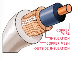
Copper CablingCopper cable is the most common form of physical network media. It is relatively cheap to install, it is easy to modify and manage, it has the ability to support multiple Media Protocols and can support relatively high speed (high bandwidth) protocols. In more detail, 1gbps over short distances.Two distinct and common forms exist; coaxial cable and twisted pair.Coaxial CableCoaxial Cable is simply a copper wire, with insulation wrapped around it, a copper mesh surrounding that with an outsider insulation. These multiple layers are referred to as "shielding" which are provided particularly when very high frequencies are being used, or where extra shielding from interference is required.Coaxial Cable is typically used for Thin Ethernet, Thick Ethernet, satellite interconnections, RF connections (Radio, TV and Microwave) and Token Ring. However, there are differences from one category to another.Frequency range that is supported, that is the capacitance and resistance of cables, changes. The physical diameter of the cable itself. Also, the materials used in insulation, shielding and conductor. The properties of the cable will effect the type and nature of the signals that can be transmitted down them.
Page 6
Twisted PairWith Twisted Pair cables, individual strands of copper wire, sheathed in PVC for insulation. It is paired and twisted with a second conductor with multiple pairs possibly included in construction.Each pair can be individually earth shielded using braiding or tin foil, which is often referred to as Shielded Twisted Pair (STP) as opposed to Unshielded Twisted Pair (UTP). A bundle of multiple pairs shielded using braiding or tin foil. A bunch of multiple pair without any shielding at all can be used for designed for low bandwidth applications such as RS232 or Voice.Copper cable in twisted pair format is classified using the Category System; Cat1, Cat2, Cat3, Cat4, Cat5, Cat5e and Cat6. The higher the category, the greater the specification.The higher the frequency (the greater the bandwidth), the higher the specification of cable required. The longer the distance, the higher the specification. In regards to the different categories, Cat1 and Cat2 was used for simple, very old telephone lines. Cat2 and Cat3 is used for modern telephone lines. Basic data cables, serial cables for example, will use Cat4. If you're looking for speed (100mbps), Cat5 needs to be used. For high speed (1000mbps), Cat5e (enhanced) needs to be used and for very high speed (1gbps to 10gbps), Cat6 needs to be used. For Cat5 and Cat6, special connectors are used to ensure high quality interconnection of nodes to cables (reducing possible signal loss and interference).
Page 7
How is Bandwidth effected. Band width (speed) is measured in bits or mega bits these days the speed can be effected by hardware or even software being used for example is there is alot of devices on one network and the software or hardware can only take a certain amount the internet speed will slow down.
Page 8
Fibre OpticFibre Optic cable uses light pulses to transmit data. It operate over large distances with two different categories; single-mode and multi-mode. Single-mode fibre transmits data at 100mbps for 2km without the signals being repeated. Multi-mode fibre transmits data at 100gbps for 100km without the signal being repeated.At one end of a fibre optic cable is a transmitter which converts electric signals from cooper wire (standard network, into light pulses. Immune to electrical interference and does not suffer from crosstalk.Each fibre can carry many independent channels, with each using a different wavelength of light. It is more difficult to hack. There are no electrical currents running through fibre optics they can be used in dangerous environments e.g. high explosive fumes, without risks of ignition. Fibre optic is harder to wiretap (physically hack).A glass fibre is composed to two parts; an inner core and an outer sheath. The inner core are used for transferring the light signal. The outer sheath, on the other hand, is used to trap the light signal in the inner core. Additionally, the individual cores are usually given a thin surface layer of coloured plastic for identification. Cores are bundled (4, 8, 12, 16, 24 and more) into a single PVC tube. The tube is usually filled with a water resistance oil jelly for added protection (a cushion). Outer PVC tube is usually Blue, Green, Violet or Black depending on the installation.Providing the light signal is within a "critical angle" - the angle of incidence to the boundary of the two glass edges, it will be "reflected". If it is outside the critical angle - it will escape the glass fibre and be lost. Fibre-optic cables usually have a minimum bend radius of 3.0cm. If the cable's bent more than this, the fibre core can develop micro-fractures, real fractures, or severely leak light. As it's the light that's carrying the network data, a loss of light means a loss of information and network errors.
Page 9
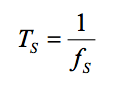
Bit-by-Bit DeliveryBit-by-Bit Delivery is a symbol rate or Baud Rate. This shouldn't be confused with Bits per Second (bps). Symbol is a pulse or tone that represents the data. The Physical Layer places these symbols on the medium at a fixed/known rate. A symbol may encode one or several bits of data.
Page 10
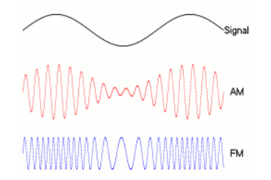
ModulationModulation is the process of modulating a signal onto a carrier. At the receiving side, a device demodulates the signals by separating the constant carrier signals from the variable data signals. For example, radio uses two types of modulation - Amplitude Modulation (AM) and Frequency Modulation (FM) - to mix audio signals with an AM or FM carrier signal. A modem modulates data by converting it to audible tones that can be transmitted on a telephone wire, and demodulates received signals to get the data.There are several modulation methods. Firstly, you have Phase Shift Keying (PSK) where a finite number of phases are used. Secondly, there is Frequency Shift Keying (FSK) where a finite number of frequencies are used. Thirdly, there is Amplitude Shift Keying (ASK) where a finite number of amplitudes are used.
Page 11
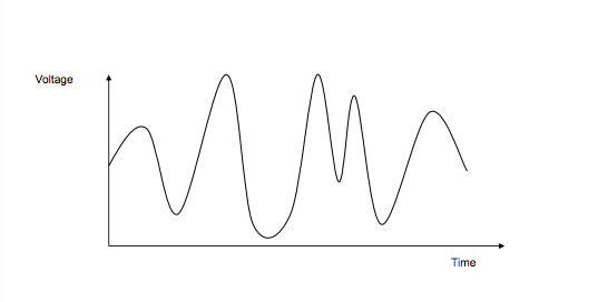
SignalsSignals can be analogue or digital. Analogue signals vary continuously and can take any value within some given range. Digital signal, on the other hand, are chosen from a discrete (limited, finite) range of possibilities. For example, {0,1} or {long, short} or {A-Z, 0-9}.Analogue Signal
Digital Signal
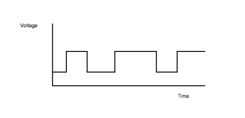
How Signals Get Damanged
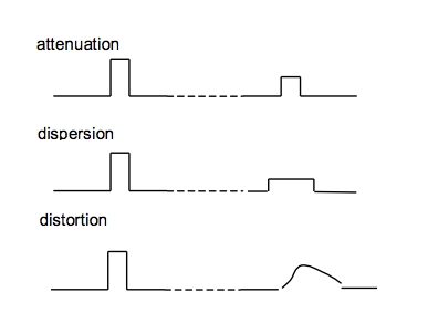
Page 12
Flow ControlFlow Control involves the managing of data rate between the sender and receiver. This prevents a slow receiver being overloaded by fast sender. Stop and Wait is the simplest form of Flow Control.Receiver says 'ready' and for each frame to be sent, it must be received before timeout. The algorithm is as follows: Sender: Transmit a singe frame Receiver: Transmit ACK as receives frame Sender receives ACK within the timeout Return to 1
Want to create your own Notes for free with GoConqr? Learn more.