
Flashcards
Dr. Fartaj for President
Flashcards do conjunto (51)
- 1Exhaust TemperaturesLight: 600-700 F
Idle: 800-900 F
WOT: 1600-1700 F
The Te increases as we increase velocity since the F/a density increases and it releases more heat - 2Heat Energy DistributionPower: 30%
Exhaust: 30%
Friction Loss: 10%
Coolant: 30%
However, as RPM increases, 50% goes into exhaust - 3Cooling System Essential ComponentsWater Jackets
Water Pump
Cooling Fan
Coolant
Heater Core
Expansion Tank
Radiator
Thermostat
Operates between 185-205 F - 4Thermostat; Details & PurposesPurpose: To speed up engine warm up and control the operating temperatures
Details: Near 185 F it opens and around 205-218 F it is wide open (T.W.O.). Contains a bypass between engine and radiator - 5Coolant; Purpose & AdditivesPurpose: Fluid to transfer heat
Additives: Ethylene Glycol (increases boiling point, reduces f.p., prevents rust).
50/50 is recommended. (60-67% for extreme cold areas)
Higher viscosity = Lower thermal conductivity and specific heat (<50% h.t.) - 6Coolant Pump; DetailsMachine that adds energy to a fluid (liquid)
Operates at 4500-5000 rpm
Can reach 150 gpm - 7Cooling fan; Purpose & DetailsPurpose: Ensures good air flow in the radiator at low speeds
Details: RWD uses 4 blades (5-6 if A/C)
FWD uses 1-2 electric fans - 8Radiator; Purpose & TypesPurpose: Transfer heat from coolant into the air by forced convection
Types: Downflow - Distributes coolant evenly but needs a higher hood line
Crossflow - Side to side flow - 9Heater Core; PurposePurpose: To heat the cabin of a car
It is a tiny radiator - 10Gas moving machines (with flow characteristics)Fan: Low pressure rise & high flow rate
Blower: Moderate pressure & flow rate
Compressor: High pressure rise & low flow rate - 11Horsepower; Water and BrakeWater Horsepower: Useful power delivered by the pump to the fluid. Proportional to the net head.
Brake Horsepower: Power delivered to the pump in order to compensate for losses due to friction, leaks, etc... - 12Pump Operating PointIntersection between the pump and system performance curves. (Pump Performance vs. System resistance)
- 13Head increases due to...Too long of a pipe
- 14Pressure Loss increases due to...Friction losses
Cooler coolant (higher viscosity)
Thermostat position (closed)
Age
Flow characteristic (laminar vs. turbulent) - 15Increasing Pump RPM causes...Higher flow rate
Higher pressure head (lower inlet, high outlet pressures) - 16Cavitation in a PumpWhen the NPSH required is higher than that available by the pump; causing bubbles in the fluid. (Intersection: The maximum volume flow rate that the pump can deliver)
- 17To avoid CavitationEnsure suction pressure (P in) is greater than the saturation pressure (P vapor).
If pump is too big --> Cavitation
If pump is too small --> Not enough flow - 18Sizing a Pump; Needed information1. Engine HP & Torque curves
2. Engine full load heat rejection
3. Pump Curves
4. Air & Coolant side heat transfer
5. Ram air flow (air in without fan)
6. Fan performance
7. Automatic transmission heat rejection - 19Boiling vs. EvaporationBoiling: The liquid to solid interface
Pool- Natural convection & bubbles (no motion)
Flow- External means (ie. Pump) (motion)
Evaporation: The liquid to gas interface
Dry air absorbs the liquid molecules - 20When inner tube wall temperature > critical flux temperature...1. Physical Damage
2. Decrease of lubrication film
3. Higher fuel consumption
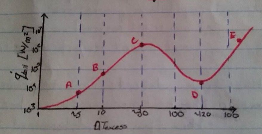
4. Thermal decomposition - 21—A-B: Convection (no bubbles)
B-C: Nucleate Boiling (small visible bubbles)
C-D: Critical Heat Flux (At pt. D, Higher wall Temperature = Lower heat transfer)
D-E: Transition Boiling Zone
E-F: Film Boiling Regime (Not tolerated in engines) - 22To reach required flow rate...1. Reduce hydraulic resistance (ie. hose bends)
2. Increase pump output
3. Decrease flow requirements - 23Thermostat CurvesOpen: Should be at BEP
Closed: Flow rate no less than 80% of open (BEP) flow rate - 24Radiator; Design & ConsiderationsAs square as possible (optimal "footprint")
Coolant velocity between 2~3 - 10 ft/s (too low leads to scale formation)
Exist temperature between Air & Coolant is 15~20 F (if less than radiator is oversize or path is too long) - 25Types of Extended Surfaces1. Tube and Plate fin (heavy trucks)
Max FPI = 14 or less
2. Tube and Spacer (cars and light trucks)
Max FPI = 21 - 26How to Improve Duty of a RadiatorIncrease the FPI (Fins per Inch), leading to an increase in Outside Surface Area
- 27Materials of a RadiatorBrass/Copper: Copper transfers heat well but is brittle (ie. Easily damaged)
Aluminum: Lighter (1/3rd), no lead to join
Cheaper (less efficient)
Can use thicker cores - 28Rating vs. SizingRating: Evaluating performance when size is specified (ie. e-NTU)
Sizing: Determining the dimensions of a HEX to meet specified performance (ie. LMTD or e-NTU) - 29How to improve heater transfer coefficient of the coolant ('h'i)2 pass will have higher velocity, leading to turbulent flow (rather than laminar)
However, as rows increases, pressure drop increases and the temperature between air and coolant decreases.. (2 is typical) - 30Assumptions made in Radiator Calculations1. Cross-flow with 2 unmixed fluids
2. Correction factor ~ 1
3. Uniform flow (in reality, false because of A/C heat load resistance, radiator grill) - 31Dimples in TubesHoles used to create turbulence by breaking the boundary layer (more effective at low Reynolds, because at high velocity it is already turbulent)
- 32Air Side Boundary LayerThinner the better (it is resisting the heat transfer)
Add louvers; creates discontinuities on the surface (3-4x more h.t. and increases pressure drop and friction thus needs a bigger fan) - 33Heat Exchangers; Required for Fin Density1. 16 to 18 FPI common in 2 row rads
2. Less FPI if core is thicker (4 row ~ 12 FPI)
3. Airflow is a function of pressure drop and radiator density (High pressure drop can lead to no possible air flow)
4. Good exit flow (2 row rad w/ poor exit flow = 4 row w/ good exit flow) - 34Vehicle to Radiator Air VelocityRadiator inlet velocity ~ 30-40% Car Speed
Airside heat transfer coefficient
'h'f = 38 x sqrt(V_car) - 35Purpose of Engine Cooling System1. Remove excess heat from the engine
2. Maintain the correct temperature
3. Get to the correct temperature ASAP - 36Air Conditioning Components; Major1. Compressor
2. Evaporator
3. Expansion Valve
4. Condenser - 37Air Conditioning Components; Minor1. Accumulator
2. Receiver
3. Magnetic Clutch
4. Filter
5. Oil Separator - 38Radiator Model Temperature GuidelinesMaximum air temp out of radiator ~ 190 F
Maximum under-hood temp ~ 225 F - 39Viscous CouplingA fluid movement causes another component to move
- 40Condenser and EvaporatorCondenser: In front of engine radiator
Evaporator: Beside heater core assembly (dash board of the vehicle)
Refrigerant enters evap. tube with low fraction as vapor, and becomes vaporized. (NOTE: Graph, not bell-curve of "Along Evaporator vs. Heat Transfer Coefficient 'h' " - 41A/C compressor; Purpose & Operating Point1. Compress gas refrigerant from low to high pressure
2. Pump refrigerant through condense, flow device and evaporator
Operating Point: Intersection of compressor RPM and refrigerant system - 42Expansion Valve; Purpose & DetailsPurpose: Throttles and Modulates/Controls
Details: Meters the systems needs to maintain cooling, modulates from W.O. to closed. (Separates the high side to the low side) - 43Scroll & Piston Compressor; Displacements (ie. Fixed, Variable, Variable Capacity Scroll), DetailsFixed: 6.1 - 12.6 cubic inches
Variable: 1 - 10 cubic inches
Variable Capacity Scroll: Max of 7.3 cubic inches with a minimum of ~3% of max
Details: Sustain 500-6000 RPM, CR of 5:1 - 8:1, any higher increases piston load and breaks down oil (High Temp). Driven by crankshaft - 44Vehicle Operating Conditions; 2 major operating curves & How to size the radiator1. Peak Torque Curves
2. Peak HP Curves
Sizing the radiator at the peak HP can protect engine at any driving condition. (May be costly due to higher design) - 45Transmission; Heat loss of Oil, Slip65% of heat loss by transmission is absorbed by the coolant
Transmission slip: Difference of input and output RPM of the transmission - 46Conditioned AirTypically: 15~17 C, 200~300 CFM
The A/C outlet location and flow rate influence thermal comfort - 47Thermal Comfort; DefinitionHumans do not feel temperature, we feel energy loss from the body.
Cooling load in vehicles is heat from solar radiation and in buses, heat from people. - 48Thermal Comfort; Influencing Factors1. Insulating Factor: Clothing
2. Physiological Factor: Age, Activity, Health
3. Environmental Factor: Air temp, Mean radiant temp, humidity, air velocity - 49Air Management System; Sections1. Air intake
2. Heater and A/C evaporator (Plenum)
3. Air distribution section - 50Air Conditioning System; Cooling CapacityTotal flow rate into passenger compartment is crucial in transient cool down (less important in steady-state)
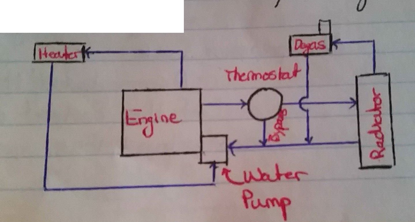
Typically, over estimate cooling capacity for quick cooling. - 51Coolant Flow Schematic
Informações
- Descrição
- Dr. Fartaj KING
- Criado por
- Simon Leblanc · ago 2017
- Atualizado
- 7 mar 2018
- Visualizações
- 22
- Tags
- Avaliação