
Basic Diff
Folien in diesem Satz (49)
-
- Galvanic
- Optical
-
- Class 1, 2, and 3 circuits are classified as remote-control, signaling, and power-limited circuits in the National Electrical Code (NEC). The NEC defines such circuits as that portion of the wiring system between the load side of the overcurrent protection device (OCPD) or the power-limited supply and all connected equipment
- These circuits are also classified in accordance with their respective voltage and power limitations.
-
- Class 1 circuits. Class 1 remote-control and signaling circuits typically operate at 120V, but the NEC permits them to operate at up to 600V [725.21(B)]. You must install these circuits within a wiring method listed in Chapter 3 of the NEC, which includes raceways, cables, and enclosures for splices and terminations [725.25].Remote-control circuit. These circuits, which control other circuits through relays or equivalent devices [100], are commonly used to operate motor controllers in moving equipment, mechanical processes, elevators, and conveyors.Signaling circuit. These circuits energize signaling equipment [100] and are typically used to operate a bell or horn, or to illuminate a light in a control panel.Power-limited circuit. These circuits are supplied by a source with a rated output of not more than 30V and 100VA [725.21(A)].
-
- Class 2 circuits. Class 2 circuits typically include wiring for low-energy (100VA or less), low-voltage (under 30V) loads such as low-voltage lighting, thermostats, PLCs, security systems, and limited-energy voice, intercom, sound, and public address systems. You can also use them for twisted-pair or coaxial local area networks (LAN) [725.41(A)(4)].
- Class 2 circuits protect against electrical fires by limiting the power to 100VA for circuits that operate at 30V or less, and 0.5VA for circuits between 30V and 150V. You protect against electric shock by limiting the current of the circuit to 5mA or less for circuits between 30V and 150V [Chapter 9, Table 11].
- You can wire Class 2 circuits with Class 2 cable or any of its substitutes permitted by Table 725.61(A), depending on the condition of use.
-
- Class 3 circuits. Use Class 3 circuits when the power demand for circuits over 30V exceeds 0.5VA, but is not more than 100VA [Chapter 9, Table 11]. We often use Class 3 signaling circuits for security systems and public address systems; voice, intercom, and sound systems; and some nurse call systems.
- Higher levels of voltage and current are permitted for Class 3 circuits (in contrast to Class 2 circuits). To prevent an electric shock hazard, the wiring must be rated no less than 300V [725.71(E) and (F)]. Wiring methods that meet this requirement include PLTC Cable, Class 3 Cable, or any of its permitted substitutions listed in Table 725.61(A), depending on the condition of use.
- *All Code references come from the 2002 NEC.
-
- Most of the structures that are called ‘earths’ become ineffective above some frequency
- related to their dimensions and style of construction, above this frequency they no longer
- provide an effective local RF reference and so can’t provide any RF control.
-
- Radiating
- conducting
- Capacitive
- Inductive
-
How are EM disturbances generated ?
- In the case of EMC we are mainly interested in radio waves or RFI (radio frequency interference). If electronic equipment is not designed and installed correctly it can function in the same way as a radio transmitter, or receiver and send out or receive RFI.
-
Good practice – Installation and Cabling
-
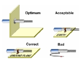
- To ensure that the lowest possible levels of radiated
- emissions occur in the >10 MHz region, supply cables
- within electronic equipment should be kept as short as
- possible. Especially those cables, connecting EMC filters
- to the mains supply.
- Output cables from switched power supply modules,
- Inverter Frequency Drives and other similar equipment,
- should be both screened and kept as short as possible.
- Where cables are screened, it is important that screening
- is carried out in the correct manne
-
Power cable routing for HF SW controllers
- In a control panel there are always areas where the interference from cables is greater than in other areas.
- A common fault is the crossing of power input and output connections to drives or filters, or running them alongside each other in trunking. This can cause high switching losses in the semiconductors, leading to component failures and should be avoided. As a general rule the level of interference increases as the clearance between cables reduces, as a squared relationship. Conversely, doubling the distance between cables quarters the level of interference.
-
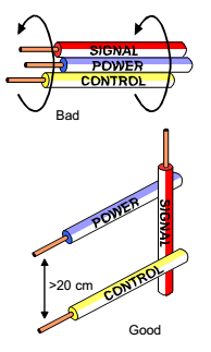
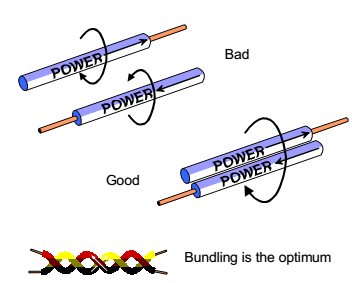
- It is important to ensure that signal, control and power cables do not run alongside each other e.g in trunking. By separating and providing sufficient clearance, or by laying signal cables at right angles to Power cables, cross-coupling can be reduced considerably
-
-
Filter Installation Guidelines
- The main components inside the filter are chokes, capacitors and resistors.
- Filters work by providing an impedance mismatch between the power line and the
- equipment, which reflects the generated noise back to its source. In order to
- maximise the impedance mismatch the choice of filter circuit should take into
- account the impedances of the source and load.
- The capacitors oppose the AC flow of electrons more at lower frequencies and less
- at higher frequencies. Inductors on the other hand react against the rate of change
- of current; they are more effective at opposing AC flow of electrons at higher
- frequencies. Therefore, a combination of series connected inductors and shunt
- connected capacitors is chosen to provide suppression over a wide frequency
- spectrum. The resistors serve to discharge the capacitors when the supply is
- disconnected and for damping resonances
-
- The filter circuit is designed to contend with two types of noise.
- There is COMMON MODE NOISE, which manifests itself as a current in phase
- in the live and neutral conductors and returns via the safety earth.
- This produces a noise voltage between live/neutral and earth. It is often
- caused by capacitive coupling to the case earth.
- The other isDIFFERENTIAL MODE NOISE produced by current flowing along either
- the live or neutral conductor and returning by the other. This produces a
- noise voltage between the live and neutral conductors.
- The differential mode chokes are larger due to the higher current handling requirement. Using a core made from a
- highly permeable material will reduce its size.
- Capacitors also fall into two groups; X Class and Y Class. The X Class capacitors are connected between live and
- neutral, or between phases, to reduce differential noise. They are tested to withstand mains voltage. Y Class
- capacitors on the other hand are more critical because they are connected between live/neutral and earth to reduce
- common mode noise. Because of this they have to be tested to ensure that they cannot fail to short circuit.
- Needless to say they are more expensive
- For higher levels of attenuation, several stages of chokes and capacitors can be added and this is known as a
- multi-stage filter.
-
- Another important factor is the earth leakage current. The larger the Y Class capacitor the more the 50 Hz current that will leak to earth, raising the potential of the filter enclosure. The maximum permissible leakage current depends on the application but to give an indication; the maximum protective earthing conductor current for handheld equipment it is 0.25 mA. Equipment that is permanently connected to the mains supply may have a leakage current of up to 3.5mA. Industrial equipment normally has higher leakage current limits (up to 5%) but in each case particular care must be taken to ensure that local earthing regulations are observed.
-
- On the following page there is a diagram showing the whole magnetic spectrum and the
- technologies that use the different wavebands. The limits for conducted (150kHz – 3MHz) and
- radiated emissions (3MHz – 1GHz) have been transposed on the diagram and this shows their
- significance in real life. They are very similar to the radio frequency bands. There is some
- discussion on increasing the limits to 3 GHz – the frequency used by 3G mobile phones.
- Interestingly the medical equipment standard EN 60601 (CISPR 11) goes up to 18 GHZ for radiated
- emissions and down to 9 kHz for conducted emissions – demonstrating just how tough these
- standards are.
-
A list of the standards in IEC 61000-2-x
- http://www.bsiglobal.com or the IEC website http://www.iec.ch and looking in their lists of current standards, or
- else look in their printed or CD-ROM catalogues.
- (Can easily purchase IEC standards with a credit card from their webstore:
- http://www.iec.ch/webstore/welcome-webstore.htm )
-
- Plastic enclosures -A plastic enclosure can prevent ESD occurring. The weak points are
- gaps for user interface controls and connectors. ESD will jump through the air
- gaps to circuitry behind. Make separation enough to prevent ESD or provide a
- preferred ESD ground path e.g. via metal back-plate. Prevent ESD/EMI entering via
- cables. Use transient suppressors and filters at cable entry points.
-
- EMC design needs a holistic approach and the best ESD immunity will involve many disciplines:-
- – ESD ground paths
- – Enclosure
- – Circuit design
- – PCB design and layout
- – Software design
- – System wiring and interconnects
- A combined view of the options and interplay of these different aspects will be required to achieve good ESD
- immunity.
-
- Key points
- • ESD immunity design requires a holistic view
- • Remember ESD has high dI/dt and dV/dt and large peak current flow – but is short duration
- • Evaluate likely ESD source entry points
- • Design enclosure and ground paths to take ESD direct to earth away from susceptible circuitry
- • Block ESD/EMI entry at connectors and cables with appropriate filters
- • Use hardware/software design to reduce basic susceptibility
- </
-
Software and firmware considerations/ESD
- Assume that any port or data line state may be corrupted - design-in ways of detecting fault states. ESD transients are short, so sample states more than once over longer time frame.Design-in safe recovery from possible fault states
-
Circuit design considerations /ESD
- Hardware can be designed to help give ESD immunity. High impedance lines will be sensitive
- to fast dV/dt therefore use lower impedances where possible, keep line lengths short and avoid
- edge triggered circuits. Low impedance loops may pick up fast dI/dt changes -minimise loop
- sizes.
-
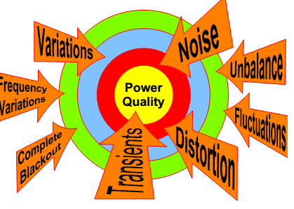
What are the main causes of power quality problems?
-
- In a situation where there is increased risk of electrical shock or damage to expensive measurement equipment, for example in a test laboratory, the use of an isolation transformer as a source of supply is recommended. ( galvanic isolation)
- The electrical characteristics of these earth paths or ground loops will differ greatly; consequently voltages may be developed in the earth as a result of small leakage currents which tend to exist in electrical/electronic equipment. Coupled with this, these ground loops can act as antennae picking up high frequency interference. Typical problems associated with groundloops are ‘humming’ from audio equipment and vertical bars on CCTV screens.
- The earth is not directly referenced to either of the phases
- in an IT system, the whole electrical system is effectively behind an isolating transformer.
- The use of an isolation transformer provides a floating supply to equipment negating the effects of these earth voltages but it also acts as consolidation point, allowing multiple earth connection at one point, reducing the possibility of earth impedance mismatch.
-
- T I , T N - S C
-
- AC currents can induce an emf on the case of an appliance. The voltage can be large enough to cause a shock. If the case is grounded, the induced emf is kept near zero.
- Current driven by the induced case emf is called a leakage current, although current does not necessarily pass from the resistor to the case.
- Galvanic isolation is used where two or more electric circuits must communicate, but their grounds may be at different potentials. It is an effective method of breaking ground loops by preventing unwanted current from flowing between two units sharing a ground conductor. Galvanic isolation is also used for safety, preventing accidental current from reaching ground through a person's body.
-
- We say that the isolated part of the circuit is "floating" with respect to the power source. Since there is no direct path for current to flow back to the power source, there is no way to keep it aligned to any reference relative to the power source. It's similar to a balloon that has nothing tethering it.
- Instead it weakly finds its own potential according to whatever tiny leakage currents are available - if you connect it to something, it will immediately align itself to the potential of whatever you connected it to. In itself, it won't put up any resistance to adopting that reference; it is not connected directly to anything that could provide resistance.
- A familiar case of galvanic isolation is a battery-powered instrument like a multimeter, since it has nothing fixing its reference potential it will float to whatever reference it is connected to; for example in itself a battery powered multimeter can be directly connected to the mains for measurements. It still works because it is floating at the mains potential, so its "0V" is at the mains potential, and its battery is "mains potential + 9V". Local to the multimeter nothing changed.
Informationen
- Beschreibung
- Folienset am Basic Diff, erstellt von harot hindi am 17/10/2017.
- Erstellt von
- harot hindi
- Aufrufe
- 1
- Bewertung