
Karteikarten
Introduction & Casting
Karten in diesem Stapel (43)
- 1Importance of Surface PropertiesMost mechanisms which lead to failure begin at the surface
Paints & varnishes need to bond to the surface
Alter the surface structure by shot peening or chemical methods - 2Process PerformanceCycle time
Quality
Reliability
Flexibility
Material utilisation
Operating cost - 3Factors which influence choice of mouldShouldn't melt when filled
Mild steel - Melting T of 1400'C can be used for some metals
For a ferrous alloy will need a ceramic mould. (Can use a metal mould but will be expensive) - 4Sand CastingUse a permanent pattern to produce cavity in sand mould
Mould destroyed but pattern used to create a large number of moulds - 5Sand Casting AdvantagesLow cost material
High melting temperature
Wide range of sizes
Economical for small (or large) quantities (if automated)
Low equipment costs - 6Sand Casting DisadvantagesPoor dimensional accuracy
Surface texture dependant on sand grain size
Labour intensive
Clearance on dowels used to locate cores reduces dimensional accuracy
Sand deforms
Silica as quartz undergoes phase change on heating leading to volume change - 7Shell MouldingSand poured over metal die
Die is heated which cures binder system
Mould coated with release agent
Can use silica / zircon which are thermally stable
Shell can be post cured in oven
Can be supported in a vat with sand / steel shot
Higher production cost than sand casting but lower capital cost (don't have to store sand) - 8Shell Moulding AdvantagesShell is permeable which allows filling of moulds with intricate details
Close control of production variables hence higher repeatability
Shell is smooth hence good flow of material
Less final machining than sand castings
Less sand used than sand castings - 9Permanent Mould CastingDies need to withstand temperature shock and wear
Large quantities required due to very expensive die
Steel is not permeable, requires vents
Die is preheated to avoid thermal shock and aid material flow
Die coated with refractory insulating lubricant to avoid surface cracking
Pour carefully to avoid turbulence
Eject ASAP to avoid hindering contraction - 10Permanent Mould Casting AdvantagesClose dimensional tolerances
Superior surface finish to sand
High conducting die - faster coolings - finer microstructure - better properties - 11Permanent Mould Casting LimitationsOnly suitable for low melting temperature alloys
High tooling costs and limitation of shapes Coatings required to protect mould from molten metal - 12Pressure Die CastingMetal injected into die at high velocity and solidifies under externally applied pressure
Filing times are extremely short to allow for complex thin walled structures - 13Pressure Die Casting Hot ChamberCrucible immersed in heat reservoir (molten metal)
Plunger used to inject metal into die
Crucible material must have higher melting temperature than metal - 14Pressure Die Casting Cold ChamberSeperates molten metal and injection system
Sufficient amount of metal inserted into shot sleeve before injected into die by piston
Higher pressures can be used than in hot chamber as the injection piston is not in contact with molten metal
Very quick - liquid metal not contaminated
Higher pressure allows for a lower material temperature
Expensive hence requires large quantities - 15Pressure Die Casting AdvantagesHigh precision due to rigidity of dies
Smooth surface finish
Cast thin structures and intricate features
Suitable for castings with large surface area
High production rates due to high automation - 16Pressure Die Casting LimitationsCores can only be used when parallel to direction of opening
Casting size limited by force available to hold die closed
Only low melting temperature alloys
Very expensive tooling
Long lead times to machine die
No machining as this would remove sound skin
Not heat treated as air in pores may expand and cause cracking - 17Pressure Die Casting PorosityLiquid metal hits end of die and rebounds causing turbulence
Avoided by controlling gate on die and injection pressure
Could use vacuum/replace air in die with oxygen - forms Al oxide inclusions which is ok for some applications - 18Investment CastingExpendable pattern and mould
Ability to make very complex shapes
Wax pattern often used
Pattern made via injection moulding - mould can be rubber for ease of removal
Pattern built up around feeding tree
Dipped in slurry & binder and covered in silica (repeated several times)
Thin ceramic shell around the wax pattern
Carefully heated to remove wax but not damage mould
Metal poured in, allowed to cool, mould broken up to release part - 19Investment Casting Self Formed CoresPattern has openings where a core is needed
Opening filled with slurry - 20Investment Casting Soluable Wax CoreCore for pattern not mould
Core made of a different wax that can be extracted without damaging the rest of the system - 21Investment Casting Preformed Refractory CoresSelf formed cores
Have size and shape limitations as you have to get slurry to fill them
Usually made of fused silica
Dissolved out in caustic bath or hydrofluoric acid after casting is removed from the mould - 22Investment Casting AdvantagesGreat internal and external complexity
Can use any castable alloy
Close dimensional tolerances due to no parting plane hence no joins and movements
Inexpensive mould material
Ability to prototype as wax is machined easily
High reliability - 23Investment Casting LimitationsLong production cycle leading to high cost per part (can cast multiple items around the tree to combat this)
Mould not reusable - 24Solidification ProblemMetal contracts when going from liquid to solid
Have to have excess liquid to fill in excess space
Excess liquid has to feed solidification front - even more of a problem when alloys grow irregularly - 25What causes porosity in castings?Evolution of dissolved gas from the liquid metal (microporosity)
Inadequate supply of liquid to make up for the volumetric contraction on solidification - 26Nucleation of Gas BubblesNucleates homogeneously on catalyst
Particles that are poorly wet by the liquid metal (inclusions) make good catalysts - 27Porosity in Castings Growth (Alloys)Undercooling at solid/liquid interface required for growth
First solid to form is rich in A
The adjacent liquid is rich in B due to this being the lower melting point constituent
B atoms attempt to diffuse into liquid
Region ahead of growth front where the T of the melt is lower than the freezing T hence, if a nipple is made, a dendritic structure will form
Growth is not planar / is irregular
THIS IS CONSTITUTIONAL UNDERCOOLING - 28Porosity in Castings Constitutional UndercoolingA steap temperature gradient through the liquid means there is no undercooled region hence planar growth is achieved
Closer to purer metal, freezing T is uniform throughout liquid = planar growth
Speed - less time for diffusion of B particles hence steaper composition gradient - Favours constitutional undercooling
Greater freezing range between the alloys means it is more prone to constitutional undercooling
Eutetic alloys have one freezing T hence no freezing range - no constitutional undercooling - 29Why are dendrites bad?Lead to semi-solid region with narrow interdendritic channels
-Difficult to feed growth front
- Solidification cracking or hot tears can occur
Impinge at a volume fraction >50% leading to increase in the viscosity of melt - fluidity decreases
Long freezing range alloys have longer semi solid region
- More prone to shrinking porosity
Last liquid to solidify is in interdendritic region and is rich in lower melting temperature constituent
Composition of alloy varies from the core of the dendrites outwards
Inclusions are swept into interdendritic channels by advancing solidification front. - 30Porosity in castings What about the solid?Last region to go solid will be rich in low melting point constituent
No homogeneous composition
Coring occurs due to no uniform composition
Core of dendrites won't melt at the same temperature as interdendritic region - 31Affect of dendritic structure on mechanical propertiesDendrites formed from a single nucleus form a single grain
Second phases often form in interdendritic regions
Second phases & grain boundaries block dislocation movement
The mechanical properties are controlled by the scale of the dendritic structure
- Defined by the secondary dendrite arm spacing
As solidification rates increase, SDAS decreases hence if we can increase solidification rates without increasing porosity we can improve mechanical properties - 32Heat flow determines...Rate of solidification
Want a high rate of solidification for a low secondary dendritic arm spacing - 33What are the thermal barriers to extracting heat?Interfacial resistance - shrinkage causes air gap between metal and mould
Resistance of mould material
Resistance of solidifying solid - 34Effect of heat flow on process cycle timeGravity & pressure die casting - might only have one, very expensive mould which you want to maximise use of.
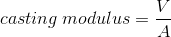
Sand casting - Long lead up time means it doesn't matter if it takes a while to cool as you need to prepare another mould - 35Casting modulusPressure die casting suited to parts with a low casting modulus i.e. low volume, high surface area
- 36What do we want to avoid when filling a mould?Air entrapment - porosity
Incorporation of impurities
- Errosion damage to mould
- Oxides formed on surface of melt
- These make good nucleation sites for gas - 37What are some features of a typical running and gating system?Increasing the cross sectional area of the feed network.
Introduce the liquid at the lowest point in casting - rises steadily without splashing
Use offset bush to ensure smooth pouring which includes a weir to catch inclusions
Tapered sprue so that as the liquid accelerates it does not pull away from the walls & aspire (suck in air)
A dross trap - the first liquid that flows into the mould will be trapped as it includes a lot of oxide - 38What is the Cosworth process?Take the liquid from the middle of the vat as large inclusions will sink and small inclusions will float.
Oxides can be broken up by turbulence and engulfed in the liquid providing excellent pore nucleation. - 39Cast IronsDon't form an oxide as the oxide reacts with carbon and becomes CO2
Graphite in the form of flakes acts as internal stress raisers forming a brittle alloy
Adding Mg to the alloy causes graphite to form in nodules - improves toughness - 40How to solve solidification shrinkage?Feed extra liquid into the caasting where it is needed i.e. the growth front
Use feeder heads - a reservoir of excess liquid which must contain sufficient liquid and not freeze before the casting freezes
Feeder head is usually same material and in the mould hence the casting modulus is the only variable we can change to alter the freezing time
Want the casting to solidify towards the feeder head
- Might have to encourage some areas of casting to solidify first
- A piece of metal inserted into a sand mould can extract heat faster in that region
- Controls temperature profile - 41Heuvers ConstructionDraw circles in cross section of mould
If these circles increase in diameter as you move towards the feeder head it will work
Can incorporate 'padding' which can be machined off in post processing or incorporated into the design
If there is an overlap between the circle and the mould this area will solidify first and the feeder head wont be able to feed it - 42Shrinkage PorosityFeeding the growth front can be made difficult by solidification
Some areas of casting can become cut off
These regions acumulate the shrinkage locally by forming internal cavities
Prevented by the use of feeder heads - 43What makes a good nucleating agent?A small Ycs value
Achieved if the catalyst has one crystal dimension similar to that of the nucleating solid
Informationen
- Beschreibung
- Karteikarten am Introduction & Casting, erstellt von tom8390 am 07/01/2015.
- Erstellt von
- tom8390
- Aufrufe
- 4
- Bewertung