
Karteikarten
coms
Karten in diesem Stapel (200)
- 1What’s the Internet: 1billions of connected
computing devices:
billions of connected
computing devices:
communication links
• fiber, copper, radio,
satellite
packet switches: forward
packets (chunks of data)
• routers and switches - 2What’s the Internet: 2 Internet: “network of networks”
• Interconnected ISPs
protocols control sending, receiving
of messages
• e.g., TCP, IP, HTTP, Skype, 802.11
Internet standards
• RFC: Request for comments
• IETF: Internet Engineering Task Force - 3What’s a protocol?protocols define format, order of
messages sent and received
among network entities, and
actions taken on message
transmission, receipt - 4network structure:network edge:
• hosts: clients and servers
access networks, physical
media: wired, wireless
communication links
network core:
• interconnected routers
• network of networks - 5DSLuse existing telephone line to central office DSLAM
< 2.5 Mbps upstream transmission rate
< 24 Mbps downstream transmission rate - 6 HFC: hybrid fiber coaxasymmetric: up to 30Mbps downstream transmission rate, 2
Mbps upstream transmission rate - 7Enterprise access networks (Ethernet) typically used in companies, universities, etc.
10 Mbps, 100Mbps, 1Gbps, 10Gbps transmission rates - 8Wireless access networkswireless LANs:
within building (100 ft.)
802.11b/g/n (WiFi): 11, 54, 450
Mbps transmission rate
wide-area wireless access
provided by telco (cellular)
operator, 10’s km
between 1 and 10 Mbps
3G, 4G: LTE - 9physical link:what lies
between transmitter &
receiver - 10guided media: v unguided media:physical v nonphysical
- 11Physical media: coax, fibercoaxial cable:
two concentric copper
conductors
fiber optic cable
high-speed operation:
low error rate:
• immune to electromagnetic
noise - 12radio link types: terrestrial microwave
LAN
wide-area
satellite - 13How do loss and delay occur?packets queue in router buffers
packet arrival rate to link (temporarily) exceeds output link
capacity - 14Packet losspacket arriving to full queue dropped (aka lost)
- 15Throughput throughput: rate (bits/time unit) at which bits
transferred between sender/receiver - 16Internet protocol stackapplication:
• FTP, SMTP, HTTP
transport:
TCP, UDP
network:
• IP, routing protocols
link:
• Ethernet, 802.111 (WiFi), PPP
physical:
bits “on the wire” - 17ISO/OSI reference modelpresentation: allow applications
to interpret meaning of data,e.g., encryption, compression,
machine-specific conventions
session: synchronization,
checkpointing, recovery of data
exchange
Internet stack “missing” these
layers!
• these services, if needed, must be
implemented in application - 18Application architectures client-server
always-on host
permanent IP address
data centers for scaling
peer-to-peer (P2P)
communicate with server
may be intermittently
connected
may have dynamic IP
addresses
do not communicate directly
with each other - 19P2P architecturepeers request service from
other peers, provide service
in return to other peers • self scalability – new
peers bring new service
capacity, as well as new
service demands - 20Sockets process sends/receives messages to/from its socket
socket analogous to door
• sending process shoves message out door
• sending process relies on transport infrastructure on
other side of door to deliver message to socket at
receiving process - 21Addressing processesto receive messages,
process must have identifier
host device has unique 32-
bit IP address - 22App-layer protocol defines types of messages
exchanged,
• e.g., request, response
message syntax:
• what fields in messages
& how fields are
delineated
message semantics
• meaning of information
in fields
rules for when and how
processes send & respond
to messages
open protocols:
defined in RFCs
allows for interoperability
e.g., HTTP, SMTP - 23What transport service does an app need?data integrity
throughput
timing
security - 24Internet transport protocols services TCP service: reliable transport between
sending and receiving
process
flow control: sender won’
t
overwhelm receiver
congestion control: throttle
sender when network
overloaded
does not provide: timing,
minimum throughput
guarantee, security
connection-oriented: setup
required between client and
server processes - 25Internet transport protocols services UDP service: unreliable data transfer
between sending and
receiving process
does not provide: reliability,
flow control, congestion
control, timing,
throughput guarantee,
security, or connection
setup, - 26HTTP overviewHTTP: hypertext
transfer protocol
Web’s application layer
protocol
client/server model
• client: browser that
requests, receives,
(using HTTP protocol)
and “displays” Web
objects
• server: Web server
sends (using HTTP
protocol) objects in
response to requests
uses TCP: - 27HTTP response status codes200 OK
• request succeeded, requested object later in this msg
301 Moved Permanently
• requested object moved, new location specified later in this msg
(Location:)
400 Bad Request
• request msg not understood by server
404 Not Found
• requested document not found on this server
505 HTTP Version Not Supported - 28Cookieswhat cookies can be used
for:
authorization
shopping carts
recommendations
user session state (Web
e-mail)
cookies and privacy:
cookies permit sites to
learn a lot about you
you may supply name and
e-mail to sites
aside
how to keep “
state
”
:
protocol endpoints: maintain state at
sender/receiver over multiple
transactions
cookies: http messages carry state - 29Electronic mail Three major components: user agents
mail servers
simple mail transfer
protocol: SMTP - 30Electronic mail User Agent a.k.a. “mail reader”
composing, editing, reading
mail messages
e.g., Outlook, Thunderbird,
iPhone mail client
outgoing, incoming
messages stored on server - 31Electronic mail: mail serversmail servers:
mailbox contains incoming
messages for user
message queue of outgoing
(to be sent) mail messages
SMTP protocol between
mail servers to send email - 32SMTP uses TCP to reliably transfer email message from
client to server, port 25
direct transfer: sending server to receiving
server
three phases of transfer
• handshaking (greeting)
• transfer of messages
• closure
command/response interaction (like HTTP)
• commands: ASCII text
• response: status code and phrase
messages must be in 7-bit ASC
SMTP uses persistent
connections
header lines, e.g.,
• To:
• From:
• Subject:
different from SMTP MAIL
FROM, RCPT TO:
commands!
body = the message - 33SMTP v http HTTP: pull
SMTP: push
both have ASCII
command/response
interaction, status codes
HTTP: each object
encapsulated in its own
response message
SMTP: multiple objects
sent in multipart message - 34Mail access protocols SMTP: delivery/storage to receiver’
s server
mail access protocol: retrieval from server
• POP: Post Office Protocol [RFC 1939]: authorization,
download
• IMAP: Internet Mail Access Protocol [RFC 1730]: more
features, including manipulation of stored messages on
server
• HTTP: gmail, Hotmail, Yahoo! Mail, etc - 35POP3 previous example uses
POP3 “download and
delete” mode
• Bob cannot re-read email
if he changes
client
POP3 “download-andkeep”:
copies of messages
on different clients
POP3 is stateless across
sessions - 36IMAP keeps all messages in one
place: at server
allows user to organize
messages in folders
keeps user state across
sessions:
• names of folders and
mappings between
message IDs and folder
name - 37DNS: domain name system: how to map between IP
address and name, and
vice versa ?
Domain Name System:
distributed database
implemented in hierarchy of
many name servers
application-layer protocol: hosts,
name servers communicate to
resolve names (address/name
translation)
• note: core Internet function,
implemented as applicationlayer
protocol
• complexity at network’
s
“edge - 38DNS: services, structureDNS services
hostname to IP address
translation
host aliasing
• canonical, alias names
mail server aliasing
load distribution
• replicated Web
servers: many IP
addresses correspond
to one name
why not centralize DNS?
single point of failure
traffic volume
distant centralized database
maintenance - 39DNS: root name servers contacted by local name server that can not resolve name
root name server:
• contacts authoritative name server if name mapping not known
• gets mapping
• returns mapping to local name server - 40TLD, authoritative serverstop-level domain (TLD) servers:
• responsible for com, org, net, edu, aero, jobs, museums,
and all top-level country domains, e.g.: uk, fr, ca, jp
• Network Solutions maintains servers for .com TLD
• Educause for .edu TLD
authoritative DNS servers:
• organization’s own DNS server(s), providing
authoritative hostname to IP mappings for organization’
s
named hosts
• can be maintained by organization or service provider - 41Attacking DNSDDoS attacks
bombard root servers
with traffic
• not successful to date
• traffic filtering
• local DNS servers cache
IPs of TLD servers,
allowing root server
bypass
bombard TLD servers
• potentially more
dangerous
redirect attacks
man-in-middle
• Intercept queries
DNS poisoning
Send bogus relies to
DNS server, which
caches
exploit DNS for DDoS
send queries with
spoofed source
address: target IP
requires amplification - 42File distribution time: P2P server transmission: must
upload at least one copy
• time to send one copy: F/us
client: each client must
download file copy
• min client download time: F/dmin
clients: as aggregate must download NF bits
• max upload rate (limiting max download rate) is us + Sui
file divided into 256Kb chunks - 43Multimedia: video video: sequence of images
displayed at constant rate
• e.g., 24 images/sec
digital image: array of pixels
• each pixel represented
by bits
coding: use redundancy
within and between images
to decrease # bits used to
encode image
• spatial (within image)
• temporal (from one
image to next) - 44Streaming multimedia: DASH DASH: Dynamic, Adaptive Streaming over HTTP
server:
• divides video file into multiple chunks
• each chunk stored, encoded at different rates
• manifest file: provides URLs for different chunks
client:
• periodically measures server-to-client bandwidth
• consulting manifest, requests one chunk at a time
• chooses maximum coding rate sustainable given
current bandwidth
• can choose different coding rates at different points
in time (depending on available bandwidth at time) - 45Streaming multimedia: DASH “intelligence” at client: client determines
• when to request chunk (so that buffer starvation, or
overflow does not occur)
• what encoding rate to request (higher quality when
more bandwidth available)
• where to request chunk (can request from URL server
that is “close” to client or has high available
bandwidth) - 46Content distribution networksstore/serve multiple copies of videos at
multiple geographically distributed sites (CDN)
• enter deep: push CDN servers deep into many access
networks
• close to users
• used by Akamai, 1700 locations
• bring home: smaller number (10’s) of larger clusters in
IXPs near (but not within) access networks
• used by Limelight - 47Content Distribution Networks (CDNs) CDN: stores copies of content at CDN nodes
• e.g. Netflix stores copies of MadMen
where’s Madmen?
manifest file
• directed to nearby copy, retrieves content
• may choose different copy if network path congested - 48Transport services and protocols provide logical communication
between app processes
running on different hosts
transport protocols run in
end systems
• send side: breaks app
messages into segments,
passes to network layer
• rcv side: reassembles
segments into messages,
passes to app layer
more than one transport
protocol available to apps
• Internet: TCP and UDP - 49Transport vs. network layer network layer: logical
communication
between hosts
transport layer:
logical
communication
between processes
• relies on, enhances,
network layer
services - 50How demultiplexing works host receives IP datagrams
• each datagram has source IP
address, destination IP
address
• each datagram carries one
transport-layer segment
• each segment has source,
destination port number
host uses IP addresses &
port numbers to direct
segment to appropriate
socket - 51UDP why? no connection
establishment (which can
add delay)
simple: no connection
state at sender, receiver
small header size
no congestion control:
UDP can blast away as fast
as desired
w - 52UDP checksumGoal: detect “
errors
” (e.g., flipped bits) in transmitted
segment - 53Reliable data transfer: getting startedwe
’ll:
incrementally develop sender, receiver sides of
reliable data transfer protocol (rdt)
consider only unidirectional data transfer
• but control info will flow on both directions!
use finite state machines (FSM) to specify sender,
receiver - 54Reliable data transfer: getting started (lost ack)approach: sender waits
“reasonable” amount of
time for ACK
retransmits if no ACK
received in this time
if pkt (or ACK) just delayed
(not lost):
• retransmission will be
duplicate, but seq. #’
s
already handles this
• receiver must specify seq
# of pkt being ACKed
requires countdown time - 55Pipelined protocolssender allows multiple, “in-flight”
, yetto-be-acknowledged
pkts
two generic forms of pipelined protocols: go-Back-N,
selective repeat - 56Go-back-N: sender can have up to
N unacked packets in
pipeline
receiver only sends
cumulative ack
• doesn’t ack packet if
there’
s a gap
sender has timer for
oldest unacked packet
• when timer expires,
retransmit all unacked
packets
ACK-only: always send ACK for correctly-received
pkt with highest in-order seq #
• may generate duplicate ACKs
• need only remember expectedseqnum
out-of-order pkt:
• discard (don’t buffer): no receiver buffering!
• re-ACK pkt with highest in-order seq # - 57Selective repeat receiver individually acknowledges all correctly
received pkts
• buffers pkts, as needed, for eventual in-order delivery
to upper layer
sender only resends pkts for which ACK not
received
• sender timer for each unACKed pkt
sender window
• N consecutive seq #’
s
• limits seq #s of sent, unACKed pkts - 58how to estimate RTT? SampleRTT: measured
time from segment
transmission until ACK
receipt
• ignore retransmissions
SampleRTT will vary, want
estimated RTT “smoother”
• average several recent
measurements, not just
current SampleRTT - 59TCP fast retransmitif sender receives 3
ACKs for same data
(“triple duplicate ACKs”),
resend unacked
segment with smallest
seq #
likely that unacked
segment lost, so don’
t
wait for timeout - 60TCP flow control receiver “advertises” free
buffer space by including
rwnd value in TCP header
of receiver-to-sender
segments
• RcvBuffer size set via
socket options (typical default
is 4096 bytes)
• many operating systems
autoadjust RcvBuffer
sender limits amount of
unacked (“in-flight”) data to
receiver’
s rwnd value
guarantees receive buffer
will not overflow - 61Connection Management (hanshake)before exchanging data, sender/receiver “handshake”
:
agree to establish connection (each knowing the other willing
to establish connection)
agree on connection parameters
2 way can fail
eg half open, forget data - 62TCP: closing a connection client, server each close their side of connection
• send TCP segment with FIN bit = 1
respond to received FIN with ACK
• on receiving FIN, ACK can be combined with own FIN
simultaneous FIN exchanges can be handled - 63Principles of congestion control informally: “too many sources sending too much
data too fast for network to handle”
different from flow control!
manifestations:
• lost packets (buffer overflow at routers)
• long delays (queueing in router buffers)
a top-10 problem! - 64TCP congestion control: additive increase multiplicative decrease approach:sender increases transmission rate (window
size), probing for usable bandwidth, until loss occurs
• additive increase: increase cwnd by 1 MSS every
RTT until loss detected
• multiplicative decrease: cut cwnd in half after loss - 65TCP Slow Start when connection begins,
increase rate
exponentially until first
loss event:
• initially cwnd = 1 MSS
• double cwnd every RTT
• done by incrementing
cwnd for every ACK
received
summary: initial rate is
slow but ramps up
exponentially fast - 66TCP throughput avg. TCP thruput as function of window size, RTT?
• ignore slow start, assume always data to send
W: window size (measured in bytes) where loss occurs
• avg. window size (# in-flight bytes) is ¾ W
• avg. thruput is 3/4W per RTT - 67TCP Fairnessfairness goal: if K TCP sessions share same
bottleneck link of bandwidth R, each should have
average rate of R/K
Why is TCP fair?
two competing sessions:
additive increase gives slope of 1, as throughout increases
multiplicative decrease decreases throughput proportionally - 68udp vs tcp fairness multimedia apps often
do not use TCP
• do not want rate
throttled by congestion
control
instead use UDP:
• send audio/video at
constant rate, tolerate
packet loss
Fairness, parallel TCP
connections
application can open
multiple parallel
connections between
two hosts
web browsers do this
e.g., link of rate R with 9
existing connections:
• new app asks for 1 TCP, gets
rate R/10
• new app asks for 11 TCPs,
gets R - 69Explicit Congestion Notification (ECN)network-assisted congestion control:
two bits in IP header (ToS field) marked by network router
to indicate congestion
congestion indication carried to receiving host
receiver (seeing congestion indication in IP datagram) )
sets ECE bit on receiver-to-sender ACK segment to
notify sender of congestion - 70Network layer transport segment from
sending to receiving host
on sending side
encapsulates segments
into datagrams
on receiving side, delivers
segments to transport
layer
network layer protocols
in every host, router
router examines header
fields in all IP datagrams
passing through it - 71network-layer functions:forwarding: move packets
from router’s input to
appropriate router output
routing: determine route
taken by packets from
source to destination - 72Switching fabrics transfer packet from input buffer to appropriate
output buffer
switching rate: rate at which packets can be
transfer from inputs to outputs
• often measured as multiple of input/output line rate
• N inputs: switching rate N times line rate desirable
three types of switching fabrics
memory bus crossbar - 73Switching via a bus datagram from input port memory
to output port memory via a
shared bus
bus contention: switching speed
limited by bus bandwidth
32 Gbps bus, Cisco 5600: sufficient
speed for access and enterprise
routers - 74Switching via interconnection network overcome bus bandwidth limitations
banyan networks, crossbar, other
interconnection nets initially
developed to connect processors in
multiprocessor
advanced design: fragmenting
datagram into fixed length cells,
switch cells through the fabric.
Cisco 12000: switches 60 Gbps
through the interconnection
network - 75Input port queuing fabric slower than input ports combined -> queueing may
occur at input queues
• queueing delay and loss due to input buffer overflow!
Head-of-the-Line (HOL) blocking: queued datagram at front
of queue prevents others in queue from moving forward - 76Output portsbuffering required from fabric faster rate
Datagram (packets) can be lost
due to congestion, lack of buffers
scheduling datagrams
priority scheduling – who gets best
performance, network neutrality - 77Output port queueing buffering when arrival rate via switch exceeds
output line speed
queueing (delay) and loss due to output port buffer
overflow! - 78How much bufferingRFC 3439 rule of thumb: average buffering equal
to
“typical” RTT (say 250 msec) times link
capacity C
• e.g., C = 10 Gpbs link: 2.5 Gbit buffer
recent recommendation: with N flows, buffering
equal to
RTT * C/sqrtR(N) - 79Scheduling mechanisms scheduling: choose next packet to send on link
FIFO (first in first out) scheduling: send in order of
arrival to queue
• real-world example?
• discard policy: if packet arrives to full queue: who to discard?
• tail drop: drop arriving packet
• priority: drop/remove on priority basis
• random: drop/remove randomly - 80Scheduling policies: prioritypriority scheduling: send
highest priority
queued packet
multiple classes, with
different priorities
• class may depend on
marking or other
header info, e.g. IP
source/dest, port
numbers, etc.
• real world example? - 81Scheduling policies: still moreRound Robin (RR) scheduling:
multiple classes
cyclically scan class queues, sending one complete
packet from each class (if available)
real world example? - 82Scheduling policies: still moreWeighted Fair Queuing (WFQ):
generalized Round Robin
each class gets weighted amount of service in
each cycle
real-world example? - 83Subnets IP address:
•subnet part - high order
bits
• host part - low order
bits
what’s a subnet ?
• device interfaces with
same subnet part of IP
address
• can physically reach
each other without
intervening router - 84Subnetsrecipe
to determine the
subnets, detach each
interface from its host
or router, creating
islands of isolated
networks
each isolated network
is called a subnet - 85IP addressing: CIDRCIDR: Classless InterDomain Routing
• subnet portion of address of arbitrary length
• address format: a.b.c.d/x, where x is # bits in
subnet portion of address - 86IP addresses: how to get one?hard-coded by system admin in a file
• Windows: control-panel->network->configuration-
>tcp/ip->properties
• UNIX: /etc/rc.config
DHCP: Dynamic Host Configuration Protocol:
dynamically get address from as server
•
“plug-and-play - 87DHCP: Dynamic Host Configuration Protocolgoal: allow host to dynamically obtain its IP address from network
server when it joins network
• can renew its lease on address in use
• allows reuse of addresses (only hold address while
connected/“
on
”)
• support for mobile users who want to join network (more
shortly) - 88DHCP overview:• host broadcasts “DHCP discover” msg [optional]
• DHCP server responds with “DHCP offer” msg [optional]
• host requests IP address: “DHCP request”
msg
• DHCP server sends address: “DHCP ack”
msg - 89DHCP: more than IP addressesDHCP can return more than just allocated IP
address on subnet:
• address of first-hop router for client
• name and IP address of DNS sever
• network mask (indicating network versus host portion
of address) - 90IP addresses: how to get one? how does an ISP get block of addresses?gets allocated portion of its provider ISP’s address
space
ICANN: Internet Corporation for Assigned
Names and Numbers http://www.icann.org/
• allocates addresses
• manages DNS
• assigns domain names, resolves disputes - 91NAT: network address translationmotivation: local network uses just one IP address as far
as outside world is concerned:
range of addresses not needed from ISP: just one
IP address for all devices
can change addresses of devices in local network
without notifying outside world
can change ISP without changing addresses of
devices in local network
devices inside local net not explicitly addressable,
visible by outside world (a security plus) - 92NAT router must: outgoing datagrams: replace (source IP address, port #) of
every outgoing datagram to (NAT IP address, new port #)
. . . remote clients/servers will respond using (NAT IP
address, new port #) as destination addr
remember (in NAT translation table) every (source IP address,
port #) to (NAT IP address, new port #) translation pair
incoming datagrams: replace (NAT IP address, new port #) in
dest fields of every incoming datagram with corresponding
(source IP address, port #) stored in NAT table - 93NAT: network address translation 16-bit port-number field:
• 60,000 simultaneous connections with a single
LAN-side address!
NAT is controversial:
• routers should only process up to layer 3
• address shortage should be solved by IPv6
• violates end-to-end argument
• NAT possibility must be taken into account by app
designers, e.g., P2P applications
• NAT traversal: what if client wants to connect
to server behind NAT? - 94IPv6: motivation initial motivation: 32-bit address space soon to be
completely allocated.
additional motivation:
• header format helps speed processing/forwarding
• header changes to facilitate QoS
IPv6 datagram format:
• fixed-length 40 byte header
• no fragmentation allowed - 95IPv6 datagram formatpriority: identify priority among datagrams in flow
flow Label: identify datagrams in same “flow.”
(concept of“flow” not well defined).
next header: identify upper layer protocol for data - 96Other changes from IPv4 checksum: removed entirely to reduce processing
time at each hop
options: allowed, but outside of header, indicated
by “Next Header” field
ICMPv6: new version of ICMP
• additional message types, e.g. “Packet Too Big”
• multicast group management functions - 97Transition from IPv4 to IPv6 not all routers can be upgraded simultaneously
• no
“flag days”
• how will network operate with mixed IPv4 and
IPv6 routers?
tunneling: IPv6 datagram carried as payload in IPv4
datagram among IPv4 routers - 98Bellman-Ford examplett
- 99Distance vector algorithmkey idea:
from time-to-time, each node sends its own
distance vector estimate to neighbors
when x receives new DV estimate from neighbor,
it updates its own DV using B-F equation: - 100Distance vector algorithmiterative, asynchronous:
each local iteration
caused by:
local link cost change
DV update message from
neighbor
distributed:
each node notifies
neighbors only when its
DV changes
• neighbors then notify their
neighbors if necessary - 101Internet approach to scalable routingaggregate routers into regions known as “
autonomous
systems
” (AS) (a.k.a. “domains”)
inter-AS routing
intra-AS routing - 102intra-AS routingintra-AS routing
routing among hosts, routers
in same AS (“network”)
all routers in AS must run
same intra-domain protocol
routers in different AS can run
different intra-domain routing
protocol
gateway router: at “edge” of
its own AS, has link(s) to
router(s) in other AS’es - 103inter-AS routingnter-AS routing
routing among AS’es
gateways perform interdomain
routing (as well
as intra-domain routing) - 104OSPF (Open Shortest Path First)
“
open
”: publicly available
uses link-state algorithm
• link state packet dissemination
• topology map at each node
• route computation using Dijkstra’s algorithm
router floods OSPF link-state advertisements to all
other routers in entire AS
• carried in OSPF messages directly over IP (rather than
TCP or UDP
• link state: for each attached link
IS-IS routing protocol: nearly identical to OSPF - 105OSPF “advanced” features security: all OSPF messages authenticated (to prevent
malicious intrusion)
multiple same-cost paths allowed (only one path in
RIP)
for each link, multiple cost metrics for different TOS
(e.g., satellite link cost set low for best effort ToS;
high for real-time ToS)
integrated uni- and multi-cast support:
• Multicast OSPF (MOSPF) uses same topology data
base as OSPF
hierarchical OSPF in large domains. - 106Hierarchical OSPF two-level hierarchy: local area, backbone.
• link-state advertisements only in area
• each nodes has detailed area topology; only know
direction (shortest path) to nets in other areas.
area border routers: “summarize” distances to nets in
own area, advertise to other Area Border routers.
backbone routers: run OSPF routing limited to
backbone.
boundary routers: connect to other AS’
es. - 107Internet inter-AS routing: BGP BGP (Border Gateway Protocol): the de facto
inter-domain routing protocol
•
“glue that holds the Internet together”
BGP provides each AS a means to:
• eBGP: obtain subnet reachability information from
neighboring ASes
• iBGP: propagate reachability information to all ASinternal
routers.
• determine “good” routes to other networks based on
reachability information and policy
allows subnet to advertise its existence to rest of
Internet: “I am here” - 108BGP basics BGP session: two BGP routers (“
peers
”) exchange BGP
messages over semi-permanent TCP connection:
• advertising paths to different destination network prefixes
(BGP is a “path vector” protocol)
when AS3 gateway router 3a advertises path AS3,X to AS2
gateway router 2c:
• AS3 promises to AS2 it will forward datagrams towards X - 109BGP messages BGP messages exchanged between peers over TCP
connection
BGP messages:
• OPEN: opens TCP connection to remote BGP peer and
authenticates sending BGP peer
• UPDATE: advertises new path (or withdraws old)
• KEEPALIVE: keeps connection alive in absence of
UPDATES; also ACKs OPEN request
• NOTIFICATION: reports errors in previous msg; also
used to close connection - 110BGP route selection router may learn about more than one route to
destination AS, selects route based on:
1. local preference value attribute: policy decision
2. shortest AS-PATH
3. closest NEXT-HOP router: hot potato routing
4. additional criteria - 111Why different Intra-, Inter-AS routing ?policy:
inter-AS: admin wants control over how its traffic
routed, who routes through its net.
intra-AS: single admin, so no policy decisions needed
scale:
hierarchical routing saves table size, reduced update
traffic
performance:
intra-AS: can focus on performance
inter-AS: policy may dominate over performance - 112Software defined networking (SDN) Internet network layer: historically has been
implemented via distributed, per-router approach
• monolithic router contains switching hardware, runs
proprietary implementation of Internet standard
protocols (IP, RIP, IS-IS, OSPF, BGP) in proprietary
router OS (e.g., Cisco IOS)
• different “middleboxes” for different network layer
functions: firewalls, load balancers, NAT boxes, ..
~2005: renewed interest in rethinking network
control plane - 113per-router control planIndividual routing algorithm components in each and every
router interact with each other in control plane to compute
forwarding tables - 114Software defined networking (SDN)Why a logically centralized control plane?
easier network management: avoid router
misconfigurations, greater flexibility of traffic flows
table-based forwarding (recall OpenFlow API)
allows “programming” routers
• centralized “programming” easier: compute tables
centrally and distribute
• distributed “programming: more difficult: compute
tables as result of distributed algorithm (protocol)
implemented in each and every router
open (non-proprietary) implementation of control
plane - 115SDN perspective: data plane switchesData plane switches
fast, simple, commodity
switches implementing
generalized data-plane
forwarding (Section 4.4) in
hardware
switch flow table computed,
installed by controller
API for table-based switch
control (e.g., OpenFlow)
• defines what is controllable and
what is not
protocol for communicating
with controller (e.g., OpenFlow - 116SDN perspective: SDN controllerSDN controller (network OS):
maintain network state
information
interacts with network
control applications “above”
via northbound API
interacts with network
switches “below” via
southbound API
implemented as distributed
system for performance,
scalability, fault-tolerance,
robustness - 117SDN perspective: control applicationsnetwork-control apps:
“brains” of control:
implement control functions
using lower-level services, API
provided by SND controller
unbundled: can be provided by
3
rd party: distinct from routing
vendor, or SDN controller - 118OpenFlow protocol operates between
controller, switch
TCP used to exchange
messages
• optional encryption
three classes of
OpenFlow messages:
• controller-to-switch
• asynchronous (switch
to controller)
• symmetric (misc) - 119OpenFlow: controller-to-switch messagesKey controller-to-switch messages
features: controller queries
switch features, switch replies
configure: controller
queries/sets switch
configuration parameters
modify-state: add, delete, modify
flow entries in the OpenFlow
tables
packet-out: controller can send
this packet out of specific
switch port
packet-in: transfer packet (and its
control) to controller. See packetout
message from controller
flow-removed: flow table entry
deleted at switch
port status: inform controller of a
change on a port. - 120OpenDaylight (ODL) controller ODL Lithium
controller
network apps may
be contained within,
or be external to
SDN controller
Service Abstraction
Layer: interconnects
internal, external
applications and
services - 121ONOS controller control apps
separate from
controller
intent framework:
high-level
specification of
service: what rather
than how
considerable
emphasis on
distributed core:
service reliability,
replication
performance scaling - 122SDN: selected challenges hardening the control plane: dependable, reliable,
performance-scalable, secure distributed system
• robustness to failures: leverage strong theory of
reliable distributed system for control plane
• dependability, security: “baked in” from day one?
networks, protocols meeting mission-specific
requirements
• e.g., real-time, ultra-reliable, ultra-secure
Internet-scaling - 123Routing algorithm classification Q: global or decentralized information?global:
all routers have complete
topology, link cost info
“link state” algorithms
decentralized:
router knows physicallyconnected
neighbors, link
costs to neighbors
iterative process of
computation, exchange of
info with neighbors
“distance vector” algorithms - 124Routing algorithm classification Q: static or dynamic?static:
routes change slowly over
time
dynamic:
routes change more
quickly
• periodic update
• in response to link
cost changes - 125A link-state routing algorithm Dijkstra’s algorithmDijkstra’s algorithm
net topology, link costs
known to all nodes
• accomplished via “link state
broadcast”
• all nodes have same info
computes least cost paths
from one node (‘
source
”)
to all other nodes
• gives forwarding table for
that node
iterative: after k
iterations, know least cost
path to k dest.’
s - 126Dijkstra’s algorithmnotation:
c(x,y): link cost from
node x to y; = ∞ if not
direct neighbors
D(v): current value of
cost of path from source
to dest. v
p(v): predecessor node
along path from source to
v
N': set of nodes whose
least cost path definitively
known - 127Distance vector algorithmkey idea:
from time-to-time, each node sends its own
distance vector estimate to neighbors
when x receives new DV estimate from neighbor,
it updates its own DV using B-F equation: - 128Bellman-Ford vs Dijkstra: Under what circumstances is Bellman-Ford better?However, Dijkstra's algorithm greedily selects the minimum-weight node that has not yet been processed, and performs this relaxation process on all of its outgoing edges; in contrast, the Bellman–Ford algorithm simply relaxes all the edges, and does this |V | − 1 times, where |V | is the number of vertices in the graph. In each of these repetitions, the number of vertices with correctly calculated distances grows, from which it follows that eventually all vertices will have their correct distances. This method allows the Bellman–Ford algorithm to be applied to a wider class of inputs than Dijkstra.
- 129Comparison of LS and DV algorithmsmessage complexity
LS: with n nodes, E links, O(nE)
msgs sent
DV: exchange between neighbors
only
• convergence time varies
speed of convergence
LS: O(n2
) algorithm requires
O(nE) msgs
• may have oscillations
DV: convergence time varies
• may be routing loops
• count-to-infinity problem
robustness: what happens if
router malfunctions?
LS:
• node can advertise incorrect
link cost
• each node computes only its
own table
DV:
• DV node can advertise
incorrect path cost
• each node’s table used by
others
• error propagate thru
network - 130Link layer: introductionterminology:
hosts and routers: nodes
communication channels that
connect adjacent nodes along
communication path: links
• wired links
• wireless links
• LANs
layer-2 packet: frame,
encapsulates datagram
data-link layer has responsibility of
transferring datagram from one node
to physically adjacent node over a link - 131Link layer: context datagram transferred by
different link protocols over
different links:
• e.g., Ethernet on first link,
frame relay on
intermediate links, 802.11
on last link
each link protocol provides
different services
• e.g., may or may not
provide rdt over link
transportation analogy:
trip from Princeton to Lausanne
• limo: Princeton to JFK
• plane: JFK to Geneva
• train: Geneva to Lausanne
tourist = datagram
transport segment =
communication link
transportation mode = link
layer protocol
travel agent = routing
algorithm - 132Link layer services framing, link access:
• encapsulate datagram into frame, adding header, trailer
• channel access if shared medium
•
“MAC” addresses used in frame headers to identify
source, destination
• different from IP address!
reliable delivery between adjacent nodes
• we learned how to do this already (chapter 3)!
• seldom used on low bit-error link (fiber, some twisted
pair)
• wireless links: high error rates
• Q: why both link-level and end-end reliability? - 133Link layer services (more) flow control:
• pacing between adjacent sending and receiving nodes
error detection:
• errors caused by signal attenuation, noise.
• receiver detects presence of errors:
• signals sender for retransmission or drops frame
error correction:
• receiver identifies and corrects bit error(s) without resorting to
retransmission
half-duplex and full-duplex
• with half duplex, nodes at both ends of link can transmit, but not
at same time - 134Where is the link layer implemented? in each and every host
link layer implemented in
“adaptor” (aka network
interface card NIC) or on a
chip
• Ethernet card, 802.11
card; Ethernet chipset
• implements link, physical
layer
attaches into host’s system
buses
combination of hardware,
software, firmware - 135two types of “links”two types of “links”
:
point-to-point
• PPP for dial-up access
• point-to-point link between Ethernet switch, host
broadcast (shared wire or medium)
• old-fashioned Ethernet
• upstream HFC
• 802.11 wireless LAN - 136Multiple access protocols single shared broadcast channel
two or more simultaneous transmissions by nodes:
interference
• collision if node receives two or more signals at the same
time
multiple access protocol
distributed algorithm that determines how nodes share
channel, i.e., determine when node can transmit
communication about channel sharing must use channel itself!
• no out-of-band channel for coordination - 137An ideal multiple access protocolgiven: broadcast channel of rate R bps
desiderata:
1. when one node wants to transmit, it can send at rate R.
2. when M nodes want to transmit, each can send at average
rate R/M
3. fully decentralized:
• no special node to coordinate transmissions
• no synchronization of clocks, slots
4. simple - 138MAC protocols: taxonomythree broad classes:
channel partitioning
• divide channel into smaller “pieces” (time slots, frequency, code)
• allocate piece to node for exclusive use
random access
• channel not divided, allow collisions
•
“
recover
” from collisions
“taking turns”
• nodes take turns, but nodes with more to send can take longer
turns - 139Channel partitioning MAC protocols: TDMATDMA: time division multiple access
access to channel in "rounds"
each station gets fixed length slot (length = packet
transmission time) in each round
unused slots go idle
example: 6-station LAN, 1,3,4 have packets to
send, slots 2,5,6 idle - 140FDMA: frequency division multiple access channel spectrum divided into frequency bands
each station assigned fixed frequency band
unused transmission time in frequency bands go idle
example: 6-station LAN, 1,3,4 have packet to send, frequency
bands 2,5,6 idle - 141random access MAC protocol specifies• how to detect collisions
• how to recover from collisions (e.g., via delayed
retransmissions)
examples of random access MAC protocols:
• slotted ALOHA
• ALOHA
• CSMA, CSMA/CD, CSMA/CA - 142Slotted ALOHA assumptions: all frames same size
time divided into equal size
slots (time to transmit 1
frame)
nodes start to transmit
only slot beginning
nodes are synchronized
if 2 or more nodes transmit
in slot, all nodes detect
collision - 143Slotted ALOHA operation: when node obtains fresh
frame, transmits in next slot
• if no collision: node can send
new frame in next slot
• if collision: node retransmits
frame in each subsequent
slot with prob. p until
success - 144Slotted ALOHA prosPros:
single active node can
continuously transmit at
full rate of channel
highly decentralized: only
slots in nodes need to be
in sync
simple - 145Slotted ALOHA consCons:
collisions, wasting slots
idle slots
nodes may be able to
detect collision in less
than time to transmit
packet
clock synchronization - 146CSMA (carrier sense multiple access)CSMA: listen before transmit:
if channel sensed idle: transmit entire frame
if channel sensed busy, defer
transmission - 147CSMA collisions collisions can still occur:
propagation delay means
two nodes may not hear
each other’
s
transmission
collision: entire packet
transmission time
wasted
• distance &
propagation delay
play role in in
determining collision
probability - 148CSMA/CD (collision detection)CSMA/CD: carrier sensing, deferral as in CSMA
• collisions detected within short time
• colliding transmissions aborted, reducing channel wastage
collision detection:
• easy in wired LANs: measure signal strengths, compare
transmitted, received signals
• difficult in wireless LANs: received signal strength
overwhelmed by local transmission strength
human analogy: the polite conversationalist - 149Ethernet CSMA/CD algorithm1. NIC receives datagram
from network layer,
creates frame
2. If NIC senses channel
idle, starts frame
transmission. If NIC
senses channel busy,
waits until channel idle,
then transmits.
3. If NIC transmits entire
frame without detecting
another transmission,
NIC is done with frame !
4. If NIC detects another
transmission while
transmitting, aborts and
sends jam signal
5. After aborting, NIC
enters binary (exponential)
backoff:
• after mth collision, NIC
chooses K at random
from {0,1,2, …, 2m-1}.
NIC waits K·512 bit
times, returns to Step 2
• longer backoff interval
with more collisions - 150“Taking turns” MAC protocols 1polling:
master node “invites”
slave nodes to transmit
in turn
typically used with
“dumb” slave devices
concerns:
• polling overhead
• latency
• single point of
failure (master) - 151“Taking turns” MAC protocols 2token passing:
control token passed from
one node to next
sequentially.
token message
concerns:
token overhead
latency
single point of failure
(token) - 152Cable access network 1 multiple 40Mbps downstream (broadcast) channels
single CMTS transmits into channels
multiple 30 Mbps upstream channels
multiple access: all users contend for certain upstream
channel time slots (others assigned) - 153Cable access network 2DOCSIS: data over cable service interface spec
FDM over upstream, downstream frequency channels
TDM upstream: some slots assigned, some have contention
• downstream MAP frame: assigns upstream slots
• request for upstream slots (and data) transmitted
random access (binary backoff) in selected slots - 154Summary of MAC protocols channel partitioning, by time, frequency or code
• Time Division, Frequency Division
random access (dynamic),
• ALOHA, S-ALOHA, CSMA, CSMA/CD
• carrier sensing: easy in some technologies (wire), hard
in others (wireless)
• CSMA/CD used in Ethernet
• CSMA/CA used in 802.11
taking turns
• polling from central site, token passing
• Bluetooth, FDDI, token ring - 155MAC addresses and ARP 32-bit IP address:
• network-layer address for interface
• used for layer 3 (network layer) forwarding
MAC (or LAN or physical or Ethernet) address:
• function: used ‘locally” to get frame from one interface to
another physically-connected interface (same network, in IPaddressing
sense)
• 48 bit MAC address (for most LANs) burned in NIC
ROM, also sometimes software settable
• e.g.: 1A-2F-BB-76-09-AD
hexadecimal (base 16) notation
(each “numeral” represents 4 bits) - 156LAN addresses and ARPeach adapter on LAN has unique LAN address
MAC address allocation administered by IEEE
manufacturer buys portion of MAC address space
(to assure uniqueness)
analogy:
• MAC address: like Social Security Number
• IP address: like postal address
MAC flat address ➜ portability
• can move LAN card from one LAN to another
IP hierarchical address not portable
• address depends on IP subnet to which node is
attached - 157ARP: address resolution protocol Question: how to determine interface’s MAC address, knowing its IP address?ARP table: each IP node (host,
router) on LAN has table
• IP/MAC address
mappings for some LAN
nodes:
< IP address; MAC address; TTL>
• TTL (Time To Live):
time after which address
mapping will be
forgotten (typically 20
min) - 158ARP protocol: same LAN A wants to send datagram
to B
• B’s MAC address not in
A’s ARP table.
A broadcasts ARP query
packet, containing B's IP
address
• destination MAC address =
FF-FF-FF-FF-FF-FF
• all nodes on LAN receive
ARP query
B receives ARP packet,
replies to A with its (B's)
MAC address
• frame sent to A’s MAC
address (unicast)
A caches (saves) IP-toMAC
address pair in its
ARP table until information
becomes old (times out)
• soft state: information that
times out (goes away)
unless refreshed
ARP is “plug-and-play”
:
• nodes create their ARP
tables without intervention
from net administrator - 159Addressing: routing to another LANwalkthrough: send datagram from A to B via R
focus on addressing – at IP (datagram) and MAC layer (frame)
assume A knows B’s IP address - 160Addressing: routing to another LAN assume A knows IP address of first hop router, R (how?)
assume A knows R’s MAC address (how?)
A creates IP datagram with IP source A, destination B
A creates link-layer frame with R's MAC address as destination address,
frame contains A-to-B IP datagram - 161Addressing: routing to another LAN frame sent from A to R
frame received at R, datagram removed, passed up to IP
R forwards datagram with IP source A, destination B
R creates link-layer frame with B's MAC address as destination address,
frame contains A-to-B IP datagram - 162Ethernet“dominant” wired LAN technology:
single chip, multiple speeds (e.g., Broadcom BCM5761)
first widely used LAN technology
simpler, cheap
kept up with speed race: 10 Mbps – 10 Gbps - 163Ethernet: physical topologybus: popular through mid 90s
• all nodes in same collision domain (can collide with each
other)
star: prevails today
• active switch in center
• each “spoke” runs a (separate) Ethernet protocol (nodes
do not collide with each other) - 164Ethernet frame structureaddresses: 6 byte source, destination MAC addresses
• if adapter receives frame with matching destination
address, or with broadcast address (e.g. ARP packet), it
passes data in frame to network layer protocol
• otherwise, adapter discards frame
type: indicates higher layer protocol (mostly IP but
others possible, e.g., Novell IPX, AppleTalk)
CRC: cyclic redundancy check at receiver
• error detected: frame is dropped - 165Error detectionEDC= Error Detection and Correction bits (redundancy)
D = Data protected by error checking, may include header fields
• Error detection not 100% reliable!
• protocol may miss some errors, but rarely
• larger EDC field yields better detection and correction - 166Internet checksum (review)goal: detect “
errors
” (e.g., flipped bits) in transmitted packet
(note: used at transport layer only) - 167Internet checksum (review) sender:treat segment contents
as sequence of 16-bit
integers
checksum: addition (1’
s
complement sum) of
segment contents
sender puts checksum
value into UDP
checksum field - 168Internet checksum (review) receiver: compute checksum of
received segment
check if computed
checksum equals checksum
field value:
• NO - error detected
• YES - no error detected.
But maybe errors
nonetheless? - 169Cyclic redundancy check more powerful error-detection coding
view data bits, D, as a binary number
choose r+1 bit pattern (generator), G
goal: choose r CRC bits, R, such that
• exactly divisible by G (modulo 2)
• receiver knows G, divides by G. If non-zero remainder:
error detected!
• can detect all burst errors less than r+1 bits
widely used in practice (Ethernet, 802.11 WiFi, ATM) - 170Ethernet switch link-layer device: takes an active role
• store, forward Ethernet frames
• examine incoming frame’s MAC address,
selectively forward frame to one-or-more
outgoing links when frame is to be forwarded on
segment, uses CSMA/CD to access segment
transparent
• hosts are unaware of presence of switches
plug-and-play, self-learning
• switches do not need to be configured - 171Switch: multiple simultaneous transmissions hosts have dedicated, direct
connection to switch
switches buffer packets
Ethernet protocol used on each
incoming link, but no collisions;
full duplex
• each link is its own collision
domain
switching: A-to-A’ and B-to-B’
can transmit simultaneously,
without collisions - 172Switch forwarding table Q: how does switch know A’ reachable via interface 4, B’ reachable via interface 5? A: each switch has a switch 6
table, each entry:
(MAC address of host, interface
to reach host, time stamp)
looks like a routing table! - 173Switch: self-learning switch learns which hosts
can be reached through
which interfaces
• when frame received,
switch “learns” location
of sender: incoming
LAN segment
• records sender/location
pair in switch table - 174Q:sending from A to G - how does S1 know to forward frame destined to G via S4 and S3 ? A:self learning! (works exactly the same as in
single-switch case!) - 175Switches vs. routersboth are store-and-forward:
routers: network-layer
devices (examine networklayer
headers)
switches: link-layer devices
(examine link-layer headers)
both have forwarding tables:
routers: compute tables using
routing algorithms, IP
addresses
switches: learn forwarding
table using flooding, learning,
MAC addresses - 176VLANs: motivation Virtual Local Area Networkconsider:
CS user moves office to EE,
but wants connect to CS
switch?
single broadcast domain:
• all layer-2 broadcast
traffic (ARP, DHCP,
unknown location of
destination MAC
address) must cross
entire LAN
• security/privacy,
efficiency issues - 177Synthesis: a day in the life of a web request• goal: identify, review, understand protocols (at all
layers) involved in seemingly simple scenario:
requesting www page
• scenario: student attaches laptop to campus network,
requests/receives www.google.com - 178Elements of a wireless network wireless hosts laptop, smartphone
run applications
may be stationary (nonmobile)
or mobile
• wireless does not always
mean mobility - 179Elements of a wireless network base station typically connected to
wired network
relay - responsible for
sending packets between
wired network and
wireless host(s) in its
“
area
”
• e.g., cell towers,
802.11 access points - 180Elements of a wireless network wireless link typically used to connect
mobile(s) to base station
also used as backbone link
multiple access protocol
coordinates link access
various data rates,
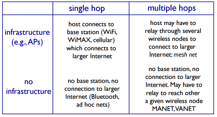
transmission distance - 181Elements of a wireless network infrastructure mode base station connects
mobiles into wired
network
handoff: mobile changes
base station providing
connection into wired
network - 182Elements of a wireless network ad hoc mode no base stations
nodes can only
transmit to other
nodes within link
coverage
nodes organize
themselves into a
network: route
among themselves - 183Wireless network taxonomy
- 184Wireless Link Characteristics (1)important differences from wired link ….
decreased signal strength: radio signal attenuates as it
propagates through matter (path loss)
interference from other sources: standardized wireless
network frequencies (e.g., 2.4 GHz) shared by other
devices (e.g., phone); devices (motors) interfere as
well
multipath propagation: radio signal reflects off objects
ground, arriving ad destination at slightly different
times - 185Wireless Link Characteristics (2) SNR: signal-to-noise ratio
• larger SNR – easier to
extract signal from noise (a
“good thing”)
SNR versus BER tradeoffs
• given physical layer: increase
power -> increase SNR-
>decrease BER
• given SNR: choose physical layer
that meets BER requirement,
giving highest thruput
• SNR may change with
mobility: dynamically adapt
physical layer (modulation
technique, rate) - 186Wireless network characteristics Hidden terminal problem B, A hear each other
B, C hear each other
A, C can not hear each other
means A, C unaware of their
interference at B - 187Code Division Multiple Access (CDMA) unique “code” assigned to each user; i.e., code set
partitioning
• all users share same frequency, but each user has own
“chipping” sequence (i.e., code) to encode data
• allows multiple users to “coexist” and transmit
simultaneously with minimal interference (if codes are
“orthogonal”)
encoded signal = (original data) X (chipping
sequence)
decoding: inner-product of encoded signal and
chipping sequence - 188IEEE 802.11 Wireless LAN802.11b
2.4-5 GHz unlicensed spectrum
up to 11 Mbps
direct sequence spread spectrum
(DSSS) in physical layer
• all hosts use same chipping
code
802.11a
5-6 GHz range
up to 54 Mbps
802.11g
2.4-5 GHz range
up to 54 Mbps
802.11n: multiple antennae
2.4-5 GHz range
up to 200 Mbps
all use CSMA/CA for multiple access
all have base-station and ad-hoc network versions - 189802.11 LAN architecture wireless host
communicates with base
station
• base station = access
point (AP)
Basic Service Set (BSS) (aka
“cell”) in infrastructure
mode contains:
• wireless hosts
• access point (AP): base
station
• ad hoc mode: hosts only - 190802.11: passive/active scanningpassive scanning:
(1) beacon frames sent from APs
(2) association Request frame sent: H1 to
selected AP
(3) association Response frame sent from
selected AP to H1 - 19102.11: passive/active scanningactive scanning:
(1) Probe Request frame broadcast
from H1
(2) Probe Response frames sent
from APs
(3) Association Request frame sent:
H1 to selected AP
(4) Association Response frame sent
from selected AP to H1 - 192IEEE 802.11: multiple access avoid collisions: 2+ nodes transmitting at same time
802.11: CSMA - sense before transmitting
• don’t collide with ongoing transmission by other node
802.11: no collision detection!
• difficult to receive (sense collisions) when transmitting due to weak
received signals (fading)
• can
’t sense all collisions in any case: hidden terminal, fading
• goal: avoid collisions: CSMA/C(ollision)A(voidance) - 193What is network security?confidentiality: only sender, intended receiver should
“understand”
message contents
• sender encrypts message
• receiver decrypts message
authentication: sender, receiver want to confirm identity of
each other
message integrity: sender, receiver want to ensure message
not altered (in transit, or afterwards) without detection
access and availability: services must be accessible and
available to users - 194Friends and enemies: Alice, Bob, Trudy well-known in network security world
Bob, Alice (lovers!) want to communicate “securely”
Trudy (intruder) may intercept, delete, add messages - 195Who might Bob, Alice be? … well, real-life Bobs and Alices!
Web browser/server for electronic transactions
(e.g., on-line purchases)
on-line banking client/server
DNS servers
routers exchanging routing table updates
other examples? - 196Q: What can a “bad guy” do?• eavesdrop: intercept messages
• actively insert messages into connection
• impersonation: can fake (spoof) source address in
packet (or any field in packet)
• hijacking: “take over” ongoing connection by
removing sender or receiver, inserting himself in
place
• denial of service: prevent service from being used
by others (e.g., by overloading resources) - 197The language of cryptographysender enycrpts
revicer decrypts - 198Breaking an encryption scheme cipher-text only attack:
Trudy has ciphertext she
can analyze
two approaches:
• brute force: search
through all keys
• statistical analysis
known-plaintext attack:
Trudy has plaintext
corresponding to ciphertext
• e.g., in monoalphabetic
cipher, Trudy determines
pairings for a,l,i,c,e,b,o,
chosen-plaintext attack:
Trudy can get ciphertext for
chosen plaintext - 199Symmetric key cryptographysymmetric key crypto: Bob and Alice share same (symmetric)
key: K
e.g., key is knowing substitution pattern in mono alphabetic
substitution cipher - 200substitution cipher: monoalphabetic cipher: substitute one letter for another
Encryption key: mapping from set of 26 letters
to set of 26 letters
Informationen
- Beschreibung
- Karteikarten am coms, erstellt von luke daniels am 09/06/2017.
- Erstellt von
- luke daniels
- Aufrufe
- 2
- Bewertung