
Mindmap
CONTROL OF THE PROCESSOR
Inhalt der Mindmap
CONTROL OF THE PROCESSOR
Functional Requirements
- Definition: Those functions that the control unit must perform
- Basic functional elements of the processor
- Registers
- Are used to store data internal to the processor.
- Some records contain necessary status information to manage the instruction sequence.
- Internal data paths
- Are used to move data between registers and between Register and ALU.
- ALU
- Is the functional essence of the computer.
- Control unit
- Causes operations to happen inside the processor.
- The control unit performs two basic tasks
- Execution
- Sequencing
- External data paths
- Are link registers to memory and I / O modules.
- Registers
- The execution of a program consists of operations involving these processor elements.
- Micro operations
- Transfer data from one register to another.
- Transfer data from a register to an external interface (e.g., system bus).
- Transfer data from an external interface to a register.
- Perform an arithmetic or logic operation, using registers for input and output
- Micro operations
- Basic functional elements of the processor
- Definition: Those functions that the control unit must perform
Control Signals
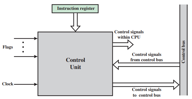
- General model of the control unit
- Inputs
- Clock
- Instruction register
- Flags
- Control signals from control bus:
- Outputs
- Control signals within the processor
- Control signals to control bus
- Inputs
- Three types of control signals are used
- Those that activate an ALU function.
- Those that activate a data path.
- Those that are signals on the external system bus or other external interface.
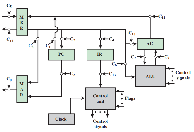
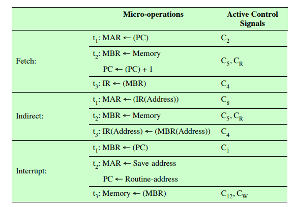
- At a given point, it knows that the fetch cycle is to be performed next.
- The first step is to transfer the contents of the PC to the MAR
- The next step is to read a word from memory into the MBR and increment the PC.
- The control unit does this by sending the following control signals simultaneously
- A control signal that opens gates, allowing the contents of the MAR on to the address bus.
- A memory read control signal on the control bus.
- A control signal that opens the gates, allowing the contents of the data bus to be stored in the MBR.
- • Control signals to logic that add 1 to the contents of the PC and store the result back to the PC.
- The control unit does this by sending the following control signals simultaneously
- The next step is to read a word from memory into the MBR and increment the PC.
- The first step is to transfer the contents of the PC to the MAR
- Data Paths and Control Signals
- General model of the control unit
A Control Signals Example
- Control signals go to three separate destinations
- Data paths
- The control unit controls the internal flow of data. For example, on instruction fetch, the contents of the memory buffer register are transferred to the instruction register
- ALU
- The control unit controls the operation of the ALU by a set of control signals. These signals activate various logic circuits and gates within the ALU.
- System bus
- The control unit sends control signals out onto the control lines of the system bus (e.g., memory READ).
- Data paths
- Control signals go to three separate destinations
Internal Processor Organization
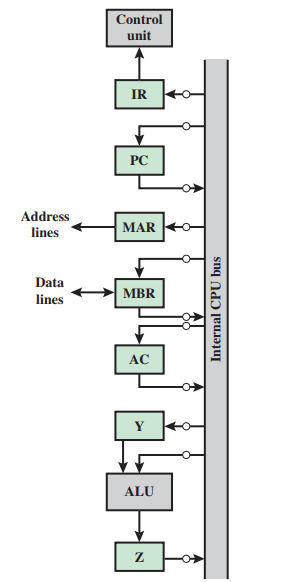
- A single internal bus connects the ALU and all processor registers. Gates and control signals are provided for movement of data on to and off the bus from each register.
- Two new registers, labeled Y and Z, have been added to the organization. These are needed for the proper operation of the ALU.
- When an operation involving two operands is performed, one can be obtained from the internal bus, but the other must be obtained from another source.
- Register Z provides temporary output storage.
- Register Y provides temporary storage for the other input.
The Intel 8085
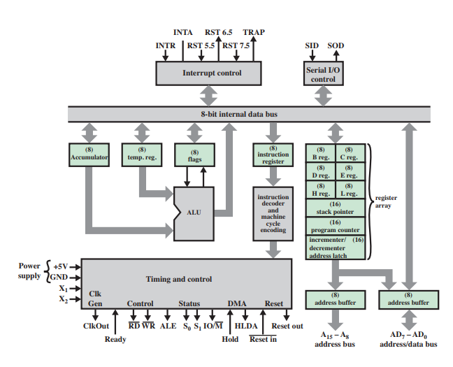
- Its organization
- Several key components that may not be self-explanatory are
- Incrementer/decrementer address latch.
- Logic that can add 1 to or subtract 1 from the contents of the stack pointer or program counter.
- Interrupt control
- This module handles multiple levels of interrupt signals.
- Serial I/O control
- This module interfaces to devices that communicate 1 bit at a time.
- Incrementer/decrementer address latch.
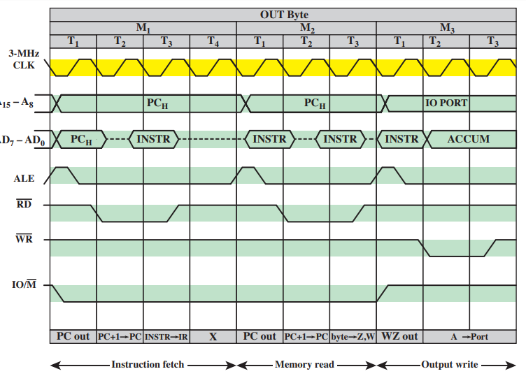
- The timing of processor operations is synchronized by the clock and controlled by the control unit with control signals.
- Each instruction cycle is divided into from one to five machine cycles
- The number of machine cycles is fixed for a given instruction but varies from one instruction to another. Machine cycles are defined to be equivalent to bus accesses. Thus, the number of machine cycles for an instruction depends on the number of times the processor must communicate with external devices.
- During the first, the OUT instruction is fetched.
- The second machine cycle fetches the second half of the instruction, which contains the number of the I/O device selected for output.
- During the third cycle, the contents of the AC are written out to the selected device over the data bus.
- The number of machine cycles is fixed for a given instruction but varies from one instruction to another. Machine cycles are defined to be equivalent to bus accesses. Thus, the number of machine cycles for an instruction depends on the number of times the processor must communicate with external devices.
- Each instruction cycle is divided into from one to five machine cycles
- Its organization
Bilder und Dateien der Mindmap
Informationen
- Beschreibung
- Mindmap am CONTROL OF THE PROCESSOR, erstellt von Diego Chacón Barrantes am 01/05/2018.
- Erstellt von
- Diego Chacón Barrantes
- Aufrufe
- 2
- Verlauf
-
- Erstellt von Diego Chacón Barrantes · 1 Mai 2018
- Kopiert von Diego Chacón Barrantes · 1 Mai 2018
- Kopiert von Diego Chacón Barrantes · 1 Mai 2018
- Bewertung