
Mindmap
Private WANs
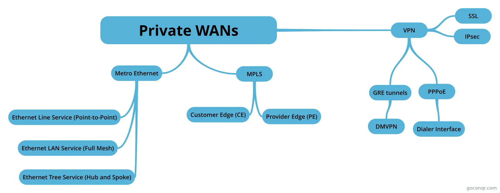
Mind map: Private WANs
Inhalt der Mindmap
Private WANs
Metro Ethernet
- Metro Ethernet is also known as carrier Ethernet
- IEEE Ethernet Standards Useful for Metro Ethernet Access Name/Speed/Distance 100Base-LX10/100Mbps/10Km 1000Base-LX/1Gbps/5Km 1000Base-LX10/1Gbps/10Km 1000Base-ZX/1Gbps/100Km 10GBase-LR/10Gbps/10Km 10GBase-ER/10Gbps/40Km
- Three MEF Service Types and Their Topologies MEF Service Name/MEF Short Name/Topology Terms/Description Ethernet Line Service/E-Line/Point-to-Point/Two customer premise equipment (CPE) devices can exchange Ethernet frames, similar in concept to a leased line. Ethernet LAN Service/E-LAN/Full mesh/Acts like a LAN, in that all devices can send frames to all other devices. Ethernet Tree Service/E-Tree/Hub-and-spoke;partial mesh; point-to-multipoint/A central site can communicate to a defined set of remote sites, but the remote sites cannot communicate directly.
- Summarizing some of these key points: -MetroE uses the concept of an Ethernet Virtual Connection (EVC), tying a committed number of bits/second called the committed information rate (CIR) to the EVC. -The access links need to be fast enough to handle the combined CIRs for all EVCs that cross the link. -For each EVC, the SP commits to forward the bits/second defined as the CIR for that EVC. -To protect its network from being overrun with too much traffic, the SP can use policing, monitoring the incoming traffic rate on each EVC and discarding traffic that goes beyond the CIR. -To protect too much of its traffic from being discarded by the SP, the customer slows down its rate of sending over the EVC to match that same CIR, using shaping on the customer router.
- Ethernet Line Service (Point-to-Point)
- The Metro Ethernet specifications define the concept of an Ethernet Virtual Connection (EVC), to define which user (customer) devices can communicate with which. By definition, an E-Line service creates a point-to-point EVC, meaning that the service allows two endpoints to communicate.
- Ethernet LAN Service (Full Mesh)
- Ethernet Tree Service (Hub and Spoke)
- The topology goes by many names: partial mesh, hub-and-spoke, and point-to-multipoint.
MPLS
- While MPLS VPNs provide a Layer 3 service to customers, MPLS itself is sometimes called a Layer 2.5 protocol, because it adds the MPLS header between the data link header (Layer 2) and the IP header (Layer 3).
- The SP's MPLS network: -Needs to know about the customer's IP subnets. -Will run IP routing protocols to learn those routes. -Will use routes about the customer's IP address space to make forwarding decisions.
- MPLS VPN service does not encrypt data.
- -A CE router does become neighbors with the PE router on the other end of the access link. -A CE router does not become neighbors with other CE routers. -The MPLS network will advertise the customer's routes between the various PE routers, so that the CE routers can learn all customer routes through their PE-CE routing protocol neighbor relationship.
- MPLS allows for a couple of variations on OSPF area design, but they all use an idea that was added to OSPF for MPLS VPNs, an idea that has to come to be known informally as the OSPF super backbone. The idea is an elegant solution that meets OSPF needs and the requirement that the MPLS PEs, when using OSPF, must be in some OSPF area: -The MPLS PEs form a backbone area by the name of a super backbone. -Each PE-CE link can be any area--a non backbone area or the backbone area.
- Customer Edge (CE)
- Provider Edge (PE)
- MPLS does route redistribution in the PE routers between the routing protocol used by the customer and a variation of BGP called Multiprotocol BGP (MPBGP). (Redistribution is needed when the PE-CE routing protocol is not BGP)
VPN
- Internet VPNs can provide important security features, like: -Confidentiality (privacy): Preventing anyone in the middle of the Internet (man in the middle) from being able to read the data. -Authentication: Verifying that the sender of the VPN packet is a legitimate device and not a device used by an attacker. -Data integrity: Verifying that the packet was not changed as the packet transited the Internet. -Anti-replay: Preventing a man in the middle from copying and later replaying the packets sent by a legitimate user, for the purpose of appearing to be a legitimate user.
- IPsec
- SSL
- GRE tunnels
- Configuring a GRE tunnel: 1-Use the interface tunnel number global command to create a tunnel interface. The interface numbers have local meaning only and do not have to match between the two routers. 2-(Optional) Use the tunnel mode gre ip interface subcommand in tunnel interface mode to tell IOS to use GRE encapsulation on the tunnel. (This is the default setting for a tunnel interface). 3-Use the ip address address mask interface subcommand to assign an IP address to the tunnel interface, using a subnet from the secure network's address range. The two routers on the tunnel should use addresses from the same subnet. 4-Configure the tunnel's source IP address in the unsecured part of the network in one of two ways. Regardless of the method, the local router's source IP address must match the other router's tunnel destination. 4A-Use the tunnel source ip-address tunnel interface subcommand to directly set the tunnel's source IP address. 4B-Use the tunnel source interface-id tunnel interface subcommand to indirectly set the tunnel's source IP address by referencing an interface on the local router. 5-Use the tunnel destination [ip-address | hostname] command to configure the tunnel's destination IP address in the unsecured part of the network. (This value must match the IP address used by the other router as its tunnel source IP address). 6-Add routes that use the tunnel by enabling a dynamic routing protocol on the tunnel or by configuring static IP routes.
- To reach an up/up state, a tunnel interface must be configured with a tunnel source command and a tunnel destination command. Additionally, the following must be true of the tunnel source: 1-If configuring the tunnel source command by referencing a source interface, the interface must -Have an IP address assigned to it -Be in an up/up state 2-If configuring the tunnel source command by referencing a source IP address, the address must -Be an address assigned to an interface on the local router -Be in an up/up state for that interface on which the address is configured. A router's tunnel interface state is also impacted by the tunnel destination configuration but those details can be a little trickier. Some settings cause IOS to accept the configuration, but cause the tunnel interface to not reach an up/up state. Other incorrect tunnel destination configuration settings cause IOS to reject the configuration. Those checks are 1-If configuring the tunnel destination command by referencing a destination IP address, the router -Must have a matching route to the destination address, or IOS will not move the tunnel interface to an up/up state -May use its default route as the matching route 2-If configuring the tunnel destination command by referencing a hostname, the router immediately attempts to resolve the name into an address per its name resolution settings. If: -The hostname does not resolve to an IP address, IOS rejects the tunnel destination command and does not store it in the configuration. -The hostname does resolve to an IP address, IOS stores that IP address in the tunnel destination command in the configuration, and does not store the hostname. Then the earlier rules about the tunnel destination IP address apply.
- DMVPN
- Cisco Dynamic Multipoint VPN (DMVPN) does more than use a multipoint GRE tunnel instead of a point-to-point tunnel. To reduce configuration, and make the operation more dynamic, DMVPN adds some dynamic processes. Those processes rely on a protocol called Next Hop Resolution Protocol (NHRP), which works as follows: 1-One site on the tunnel acts as the hub site and as NHRP server. 2-The spoke sites initially can communicate only with the hub site. 3-The hub sites (as NHRP clients) register their matching public and private IP addresses with the NHRP server (using NHRP protocol messages). (This is a key step in avoiding any configuration on the hub router for each new hub site added to the network.)
- PPPoE
- For PPPoE, the dialer interface holds configuration for IP and PPP, but it is not a physical Ethernet interface. So, to let the dialer interface use G0/1 as the physical interface in this scenario: -The configuration puts interface G0/1 into a dial pool, specifically numbered dial pool 1, per the pppoe-client dial-pool-number 1 command. This command means that G0/1 is available to be used by dialer interfaces wanting to do PPPoE. -Dialer interface 2 references dial pool number 1 with the dialer-pool 1 command. Because the dial pool number matches, interface dialer 2 will use G0/1 for PPPoE.
- PPPoE Configuration Summary: 1- Configure Layer 1 details. 1A-Configure a dialer interface: I-Use the interface dialer number command to create the dialer interface; choose a number not already used on the local router by some other dialer interface. II-Use the dialer-pool number interface subcommand to refer to a pool of Ethernet-family interfaces that can be used for PPPoE. 1B-Configure the physical interface(s): I-Use the pppoe-client dial-pool-number number interface subcommand to add the interface to the same pool number configured on the dialer interface. 2-Configure Layer 2 details. 2A-Configure PPP on the dialer interface: I-Use the encapsulation ppp interface subcommand to enable PPP on the dialer interface. II-Use the ppp chap hostname name interface subcommand to define the username with which to authenticate to the ISP. III-Use the ppp chap password password interface subcommand to define the password with which to authenticate to the ISP. 2B-Configure PPPoE on the Ethernet interface(s): I-Use the pppoe enable interface subcommand to enable PPPoE. (IOS adds this command automatically when the pppoe-client interface subcommand is configured). 3-Configure Layer 3 details. 3A-Configure IP on the dialer interface: I-Use the ip address negotiated interface subcommand to tell the dialer interface to use PPP's IPCP to learn the IP address to use. II-Use the mtu 1492 interface subcommand to change from the default of 1500 to allow for the 8 extra header bytes used by PPPoE. 3B-Disable IP on the Ethernet interface(s): I-Use the no ip address interface subcommand to disable IP routing on the physical interface and remove the IPv4 address from the interface.
- Dialer Interface
Informationen
- Beschreibung
- Ingeniería Mindmap am Private WANs, erstellt von Alejandro Castillo am 10/10/2018.
- Erstellt von
- Alejandro Castillo
- Aufrufe
- 1
- Bewertung