
Mindmap
Polymer Electrolyte Fuel Cells
Inhalt der Mindmap
Polymer Electrolyte Fuel Cells
1 GAS CHANNELS & FLOW FIELD (8)
- GEOMETRICAL CONSTRAINTS
- Geometry of flow needs to EVENLY DISTRIBUTE REACTANT throughout field
- e.g. Meander, square, parallel, interdigitated
- At low T fuel cells can produce liq. H2O => form blockage if there is insufficient flow
- Constraints
- must connect air & H2 chambers
- At same current density need to provide ~2.5x flow of air compared to H2
- ELECTRICAL CONDUCTIVITY & CONTACT RESISTANCE
- Bipolar plates have high conductivity BUT
- low contact resistance to gas transport layer
- => if the lateral conductivity isn't high => local reversal of potential
- Contact resistance 5x effect of bulk resistance
- low contact resistance to gas transport layer
- Increasing clamping pressure may help, but results in “tenting”
- gas transport layer is pushed into the channel, making gas distribution more difficult
- Bipolar plates have high conductivity BUT
- CURRENT & REACTANT DISTRIBUTION
- As reactant flows along channel it is consumed => Reactant conc varies along channel
- want to achieve even distribution of reactivity rate across plate
- Want distribution to be HOMOGENEOUS
- want to achieve even distribution of reactivity rate across plate
- Amount of ox has to = amount of red => [H+] is fixed
- Rate of run limited by H+ production => flow of H+ is dominated by migration => driving force is electric field
- Conductivity of electrolyte is low => anode & cathode runs are strongly coupled
- Local current density may be controlled by rate of either anode or cathode => whichever is smaller
- As reactant flows along channel it is consumed => Reactant conc varies along channel
- HEAT REMOVAL
- If fuel cell at 40% => 60% heat loss
- low grade/low temp => difficult to get rid off
- Bipolar plates: integral channels for cooling H2O
- CORROSION RESISTANT
- Typical electrolyte: superacid pKa~-6
- highly corrosive towards metals
- Fe & other TMS used in degradation of membrane materials
- Metal oxides films highly resistant to corrosion e.g. Al2O3
- Typical electrolyte: superacid pKa~-6
- WATER REMOVAL
- See paper notes
- EXAMPLE & STRUCTURE
- Bipolar Plates: used to conduct current from +ive electrode of one cell to -ive of the next
- Plates should be gas impervious
- thin and lwt
- Power density critically effected by thickness
- thin and lwt
- Plates should be gas impervious
- E.g.
- e.g. Stainless steel or graphite (high Ts)
- Injected moulded carbon/plastic composites (low Ts)
- Stamped steel w/ anti-corrosion coatings
- Bipolar Plates: used to conduct current from +ive electrode of one cell to -ive of the next
- The gas channels and flow fields distribute reactants through the fuel cell and channel current through the stack
- GEOMETRICAL CONSTRAINTS
2 GAS TRANSPORT LAYER (4)
- ELECTRICAL CONDUCTIVTY
- In plane conductivity >10x higher than through plane
- All fibres are in plane
- anistropy => current flows well through fibres but not b/w
- All fibres are in plane
- Contact resistance is important
- In plane conductivity >10x higher than through plane
- REACTANT & TRANSPORT PROPERTIES
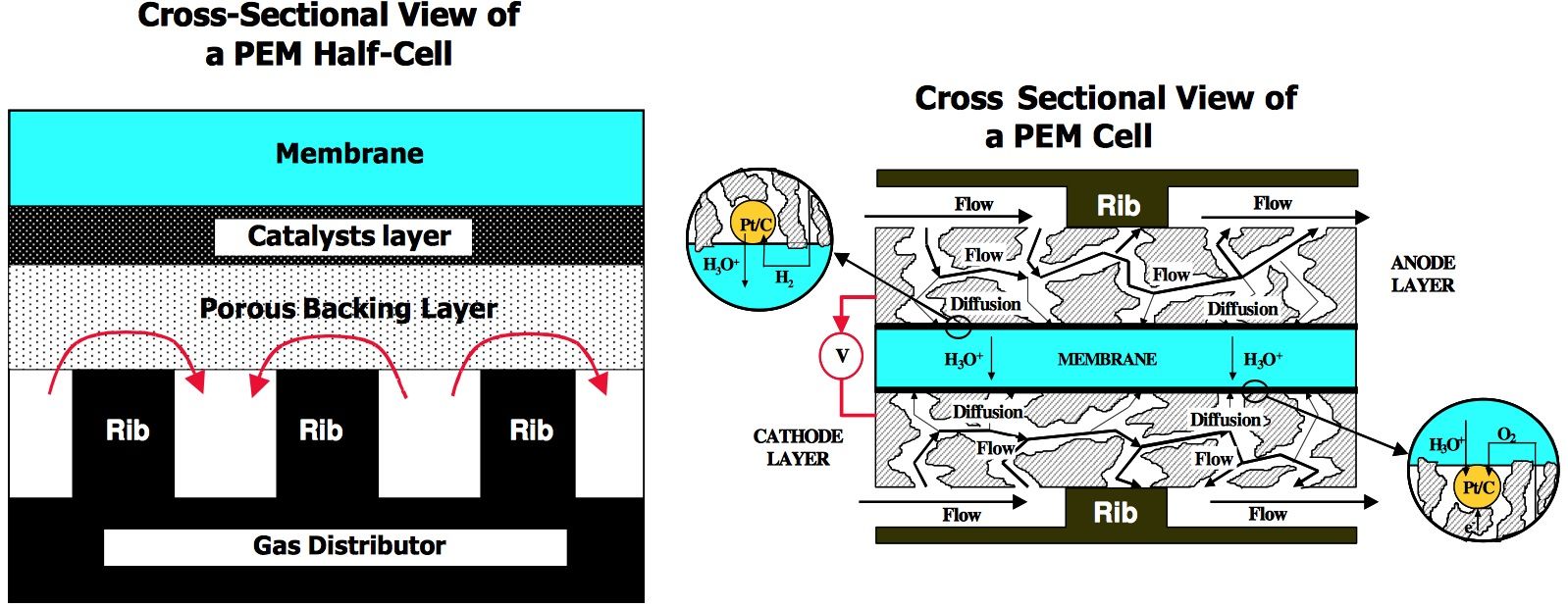
- Need gas to penetrate under ribs
- Flow under rib b/c 1) diffusion or 2) pressure b/w channels
- => need layer to be highly porous
- Flow under rib b/c 1) diffusion or 2) pressure b/w channels
- Need gas to penetrate under ribs
- MECHANICAL PROPERTIES
- WATER TRANSPORT PROPERTIES
- Hydrophobicity introduced by adding ptfe emulsion to gas trans layer & sintering at 360C
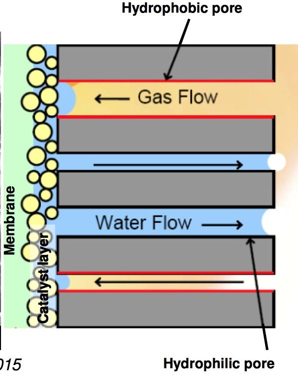
- If totally imbibed w/ H2O => gas can't get through
- But cathode layer produces H2O so need to allow H2O into chain
- => need hydrophobic & hydrophilic pores
- But cathode layer produces H2O so need to allow H2O into chain
- If totally imbibed w/ H2O => gas can't get through
- Hydrophobicity introduced by adding ptfe emulsion to gas trans layer & sintering at 360C
- EXAMPLES
- Composed of carbon fibre e.g. PAN
- Fibre: thermally decomposed T 2500
- Paper: thin, flat, brittle
- Cloths: woven, stronger, thicker
- Felt: layers powder bound together
- Composed of carbon fibre e.g. PAN
- IS RESPONSIBLE FOR COLLECTING CURRENT & TRANSPORTING IT TO THE RIBS OF THE FLOW FIELD
- PROVIDES AN ELECTRICALLY CONDUCTIVE BACKING MATERIAL FOR THE ELECTRODES
- ELECTRICAL CONDUCTIVTY
3 THE MICROPOROUS LAYER (3)
- POROSITY
- Needs to have pore size b/w cat layer (<1um) & gas transport layer (100um)
- ELECTRICAL CONDUCTION
- WATER TRANSPORT PROPERTIES
- Difficult to measured as buried under GTL => can use neutron radiography or X-Ray tomography
- Need compromise between hydrophobicity and hydrophilicty or there will be a H2O build up somewhere
- EXAMPLES
- Composed of carbon & hydrophobic material e.g. ptfe
- MPL produced by mixing carbon powder, ptfe solution and a pore former to produce an ink
- Ink is screen printed or sprayed on gas transport layer
- FUTURE DESIGN
- Use carbon nanotubes: MWNTs, expensive
- Improve properties => better distribution of pores
- Use carbon nanotubes: MWNTs, expensive
- B/W gas transport layer (del large pores) & cat layer (fine pores)
- No reaction happening: acts as buffer layer & as support to keep things flat
- prevent thin cat layer being extruded into GTL
- Conduct current
- Aid water management
- POROSITY
4 CATALYST LAYER
- PROPERTIES
- Good proton/e- transport
- Good H2O handling properties
- High porosity & good reactant transport properties
- Good long term stability
- Electrochemical rxns occur in catalyst layer
- FUTURE DESIGN
- Production of ultra thin cat layers using SPUTTERING
- Nanostructural delevopment of cat layers using regular structured substrates
- Ultralow loading electrodes
- ISSUES TO BE CONSIDERED
- Issues with producing catalyst layers
- interface is buried
- No clear relationship b/w fabrication methods & layer properties
- Amounts
- Amount of soluble Nafion
- Amount of catalyst
- Amount of porous volume
- OTHER
- Delamination of cat layer from membrane => leads to local regions where no reactions occur
- Thickness variation leads to greater gas crossover & thermal runaway => leads to pinholes
- Cracks can also lead to pinhole formation in the membrane material
- Issues with producing catalyst layers
- TWO TYPES: b/c in water/Nafion permeability of reactants is low but much higher in gas phase
- ULTRA THIN
- Difficult to produce but uniformly polarised
- Proton conduction is fast and we only have to worry about local potential & diffusion of reactants
- Water handling: flooding decreases the available pore volume
- Can be modelled as a change in the effective diffusion coefficient of air
- As diffusion coefficient approaches that found in pure H2O the performance becomes v poor
- Can be modelled as a change in the effective diffusion coefficient of air
- THICK
- Thicker layers with gaseous pores throughout the layer to increase mass transport
- Effect of finite conductivity of carbon => non-uniform potential distribution
- Want low cathode potential
- Higher porosity leads to better distribution of reactant
- ULTRA THIN
- PROPERTIES
4a CATALYST SUPPORT (5)
- Improves dispersion of catalyst
- Have high surface area
- => distribute cat as uniformly as poss
- Particles have para-crystalline structures
- Morphology & particle size distribution is dependent on the source material & the process of thermal decomposition
- Be electrically conductive
- Be pure (2)
- Addition of H3PO4 or ZnCl2 to precursor gets rid of halides
- Steam &/ CO2 at 800-1100C gets rid of amorphous C
- Be corrosion resistant
- Loss of cat SA => strong effect on performance
- Highest loss seen on highest SA carbon
- Effect is smaller when high Pt loading used
- Highest loss seen on highest SA carbon
- Loss of cat SA => strong effect on performance
- Common structure
- ~40nm C primary spherical particles
- Future design
- Aerogel
- v. open support => v. sharp pore size distribution
- Small pores, high Pt
- High electrical conductivity
- Carbon nanotube
- 10% wt loading; MWNTs w/ d=30nm
- May show better oxidative stability & electrical conductivity
- hydrophobic, hard to get Pt to stick
- Aerogel
4b THE CATALYST (8)
- Catalyse the electrochemical reactions leading to hydrogen oxidation & oxygen reduction
- HIGH ACTIVITY FOR REACTIONS
- HOR
- H2 -> 2H+ +2e-
- fast kinetics
- Tafel-Volmer kinetics (see notes)
- Little economic incentive to replace Pt on anode if using pure H2 as a fuel
- ORR
- H2O2 produced => bad b/c strong oxidant
- Activity for oxygen reduction is modified because formation of oxide at high potential
- BIG LIMITATION: Pt starts activity at too low a potential
- Volcano plot
- HOR
- LARGE SURFACE AREA & SA/WEIGHT
- smaller not necessarily better
- trade off b/w surface activity & SA
- Try to disperse cat as much as poss => want large SA
- decrease area => activity/unit area starts dropping off
- Too small can force particles to expose 'wrong' crystal face
- trade off b/w surface activity & SA
- smaller not necessarily better
- RESISTANCE TO POISONING: FUEL DEPENDENT
- Major poisons: CO, Cl & S containing compounds
- See notes for CO removal
- Use PtRu
- See notes for CO removal
- can act revers/irreversibly w/ cat
- Poisons bind stronger to cat than reactant
- leads to a decrease in effective SA
- Rate of loss dependent upon composition
- PtCo retains SA better than Pt
- Take into account both surface loss & activity loss
- Rate of loss dependent upon composition
- leads to a decrease in effective SA
- only a small amount req as only monolayer needed to block reactant
- Major poisons: CO, Cl & S containing compounds
- GOOD CHEMICAL STABILITY: CORROSION RESISTANT
- RETAIN SA OVER TIME
- SHOW A LONG LIFE
- INEXPENSIVE
- EXAMPLE OF STRUCTURE
- Pt or Pt alloys => high activity & stability
- Usually dispersed on high surface area carbon to increase the specific SA
- Pt w/ H2; PtRu w/ reformate
- Cathode: Pt, PtCo or PtCr
- Pt or Pt alloys => high activity & stability
- CORE-SHELL CATALYSTS
- Put Pt on surface where it is most valuable & place other metal in core
- Core metal mustn't corrode
- Pt should surface segregate
- Possibility of modifying electronic structure
- defects poss
- Put Pt on surface where it is most valuable & place other metal in core
- FUTURE MATERIALS
- Mesoporous catalysts
- unsupported so less problems w/ C corrosion
- SA comes from internal porous structure
- Produced by utilising a templating material
- Mesoporous catalysts
5 PROTON TRANSPORT MEMBRANE MATERIALS (6)
- SHOW GOOD PROTON CONDUCTIVITY BUT NO ELECTRICAL CONDUCTIVITY (3)
- EQUIVALENT WEIGHT
- The lower the EW the larger the no. of ion exchange sites
- Polymer stability is reduced at low EW - dissolution occurs
- Conductivity extremely sensitive to water content
- Rapid transfer of H2O through Nafion b/c interconnection b/w sulphonic groups
- PERCOLATION NETWORK
- Proton conductivity due to the formation of a percolation network through the membrane
- Strongly dependent upon amount of H2O present
- Nafion proton density ~1M H2SO4
- Proton mobility ~1/10th that of 1M H2SO4
- Proton conductivity due to the formation of a percolation network through the membrane
- Grottius vs Vehicular see notes
- VEHICULAR MECHANISM
- Proton attached to solvent e.g. H3O+
- Moves at rate of vehicular diffusion
- Vehicle counter diffusion possible
- Moves at rate of vehicular diffusion
- Proton attached to solvent e.g. H3O+
- GROTTIUS MECHANISM
- Stationary vehicles, only local motion, hopping
- Always w/i H bond environment
- Solvent reorientation provides H+ pathway
- Always w/i H bond environment
- At low T FCS; Higher conductivity
- Stationary vehicles, only local motion, hopping
- VEHICULAR MECHANISM
- EQUIVALENT WEIGHT
- PREVENT CROSSOVER OF GASES BUT HAVE GOOD WATER TRANSPORT
- GAS CROSSOVER IN MEMBRANE NOT BENEFICIAL (4)
- Permeability related to conc & diffusion coefficient of gases in membrane
- H2 & O2 may chemically recombine
- Permeation b/w anode & cathode is bad => chemically react/recombine => use resources & produces heat
- Leads to pinhole formation & direct recombination
- Flux dependent on thickness => thin section => hot spot => snow-ball effect
- Current associated w/ gas crossover is a few mAcm-2
- Nitrogen crossover into anode side still req purging
- WATER ISSUE
- Enters cell on anode & cathode => humidified gas
- Transported from anode to cathode => ELECTROSMOTIC DRAG
- Anode side depleting => conductivity by anode drops
- Electrosmotic drag proportional to current
- Electrosmotic drag drys out anode => leads to excess H2O at cathode
- Too much H2O will flood cathode
- Diffuses from the cathode to anode => BACK DIFFUSION
- Water is produced at cathode
- SOLUTION: make membrane thiner & increase back diffusion
- Decrease dx: Fick's Law J=-D dc/dx
- Also reduces resistance & material req
- PROBLEMS: easier to tear & gas transport depends on thickness
- GAS CROSSOVER IN MEMBRANE NOT BENEFICIAL (4)
- BE CHEMICALLY & ELECTROCHEMICALLY COMPATIBLE W/ ELECTROCATALYST
- Operating conditions are chemically hostile
- acidic pH, pKa~-7
- High potential on cathode side: oxidising
- Low potential on anode side: reducing
- Production of H2O2, .OH & .OOH poss (see notes)
- Leads to degradation of solid polymer electrolyte and other MEAs
- H2O2 undergoes autocatalytic decomp. in presence of Pt
- => most damage occurs in membrane adj to cat layer
- 2H2O2 --Pt--> 2H2O + O2
- => most damage occurs in membrane adj to cat layer
- H2O2 undergoes autocatalytic decomp. in presence of Pt
- Chemical degrade of pFSA materials proceeds via H2O2 radical attack
- Produces F- & low wt perfluorosulfonic acid species
- Aliphatic hydrogens are v susceptible to degrad
- Leads to degradation of solid polymer electrolyte and other MEAs
- Operating conditions are chemically hostile
- SHOW GOOD MECHANICAL PROPERTIES
- SHOW A LONG LIFE
- BE INEXPENSIVE
- Aims
- Reduce cost of materials
- Improve operating temperature
- Future design
- Use Nafion w/ some inorganic material to prevent dehydration e.g. SiO2
- use new inorganic materials which are proton conducting themselves
- Use materials which don't req H2O to show proton conduction
- Use anion conducting membrane materials
- Use Nafion w/ some inorganic material to prevent dehydration e.g. SiO2
- Aims
- COMMON STRUCTURE
- Nafion: like ptfe w/ attached ion exchange group
- Superacid ~-6 H+ from SO3H v labile
- Conductivity highly dependent on H2O content
- Phase separation causes formation of hydrophilic & hydrophobic domains
- Nafion: like ptfe w/ attached ion exchange group
- SHOW GOOD PROTON CONDUCTIVITY BUT NO ELECTRICAL CONDUCTIVITY (3)
Bilder und Dateien der Mindmap
Informationen
- Beschreibung
- Mindmap am Polymer Electrolyte Fuel Cells, erstellt von onebigrat am 02/05/2015.
- Erstellt von
- onebigrat
- Aufrufe
- 0
- Bewertung