Part 2: Electrons in Solids

Beschreibung

Graduação Solid State Mindmap am Part 2: Electrons in Solids, erstellt von eg612 am 06/03/2014.
eg612
Mindmap von eg612, aktualisiert more than 1 year ago
eg612
Erstellt von eg612 vor etwa 10 Jahre
42
0

Zusammenfassung der Ressource

Part 2: Electrons in Solids
  1. Weak binding (FEM)
    1. Tight binding
      1. Energy band structure

        Anmerkungen:

        • - Arises from both models. - Energy gap increases with Vo. - Position of Ef is determined by the number of valence electrons per unit cell.
        1. Insulators (Large energy gap, Ef inside it, no Fermi surface)
          1. Semiconductors: small energy gap, Ef inside it, no Fermi surface
            1. Metals: Ef is inside energy band

              Anmerkungen:

              • Away from edge, FEM holds
              1. Brillouin zones

                Anmerkungen:

                • A BZ contains a set of wavevectors which spans the space of all wavevectors which can be scattered by the crystal. All wave vectors in other BZ's satisfy k'=k+G (Laue's condition), where G is a reciprocal lattice vector.
                1. Different BZ's correspond to different energy bands

                  Anmerkungen:

                  • Energy gaps coincide with BZ boundaries (surfaces) Energy bands lie in different BZs
                  1. 3 Zone schemes
                    1. Extended
                      1. Periodic
                        1. Reduced
                      2. Anmerkungen:

                        • As an electron jumps from the valence band to the conduction band, a positively charged hole is left. Same properties as electron but positively charged!
                    2. Density of charge carriers in semiconductors (IMPORTANT DERIVATION!
                      1. Density of states (TO REMEMBER)
                        1. Occupation number (FD distribution) (TO REMEMBER)

                          Anmerkungen:

                          • Remember to approximate with simple exponential as the exponential in the denominator becomes >> 1
                          1. Of electrons f_FD
                            1. Of holes: 1-f_FD (remember to rearrange)
                              1. Change variable and integrate to get Number of charge carriers + multiply by 2 for spin
                                1. K and Real space diagrams for charge carrier densities
                                  1. Electrons are in conduction band minima
                                    1. Holes are in valence band maxima
                                    2. Product of n and p only depends on energy gap E_g.
                                      1. For intrinsic semiconductors n=p=n_i=p_i

                                        Anmerkungen:

                                        • e.g. Ge, Si, GaAs
                                        1. n=p=n_i=p_i=sqrt(np) are fully specified by E_g
                                        2. Extrinsic semiconductors. Dopants: donors have valence >; acceptors have valence < (donate holes)
                                          1. Have extrinsic carriers from dopants
                                            1. Usually dopant density >> intrinsic density => dopants dominate conduction properties at normal T's
                                            2. n-type semiconductors: electrons = majority carriers; holes = minority carriers
                                              1. p-type semiconductors: holes = majority carriers; electrons = minority carriers
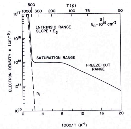
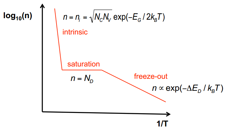
                                                1. Temperature dependence of conductivity
                                                  1. At low T: extrinsic carriers are frozen out, Intrinsic carriers dominate
                                                    1. In saturation region (T about 300K): dopants are fully ionised and dominate conduction properties. This is the operating range of the device.
                                                      1. At T>>300K semiconductor ionises and intrinsic carriers dominate
                                                      2. Insulators have no dopants
                                                    2. n = N_c*e^((E_c-E_f)/k_b*T)
                                                      1. dn/dx = -(dE_c/dx)*n/k_b*T
                                                2. Holes: empty states in otherwise filled bands
                                                3. Bloch States: - 2 separate bands for conduction and valence. - Use m*
                                                  1. Derivation of m*
                                                  2. FEM: - dispersion relation is a parabola on which states lie. - Use m
                                                    1. Conduction in semiconductors
                                                      1. In FEM
                                                        1. Filled states form a Fermi sphere in k-space

                                                          Anmerkungen:

                                                          • Radius k_f of the sphere was derived in Part 1 of the course.
                                                          1. k is related linearly to momentum and velocity of electrons
                                                            1. For each electron going in +k there is one in -k => no net current
                                                              1. Apply E field
                                                                1. Use De Broglie relation to express dk = (-eE/h_bar)dt
                                                                  1. Now electrons are shifting to higher k values => Fermi sphere is moving => current
                                                                    1. Scattering slows down the increase in velocity of Fermi sphere by knocking electrons back to empty states in the valence band

                                                                      Anmerkungen:

                                                                      • Electrons at the leading edge (in the Fermi sphere, k.-space) are scattered back to the opposite edge.
                                                                      1. Given a scattering time t, dk/dt settles down at -(eE/h_bar)t => Steady State
                                                                        1. Drift velocity: v_drift = (eE/m)t of all electrons in the sphere

                                                                          Anmerkungen:

                                                                          • where et/m = u (carrier mobility)
                                                                  2. Energy of level E_c = -eV + const. Moreover: E_field = -dV/dx
                                                                    1. Hence, dE_c/dx = -edV/dx = e*E_field
                                                                      1. dn/dx = -e*E_field*n/k_b*T
                                                                        1. Einstein's relation: D_n/u_n = k_b*T/e
                                                              2. In real solids same thing except that
                                                                1. m* instead of m and have + sign for holes
                                                                  1. Charge transport occurs separately in the valence and in the conduction band
                                                                    1. Collisions can knock electrons to other band or other state in the same band
                                                                      1. Different sources of scattering

                                                                        Anmerkungen:

                                                                        • Temperature dependent: - Scattering from acoustic and optical phonons, dominates at high temperatures. - Scattering from ionised donor centres. Important for devices. Temperature independent: - Scattering from crystal defects, dominates at low temperatures. 
                                                                        1. T dependent: phonons, ionised dopant centres
                                                                          1. T independent: crystal defects
                                                                        2. Charge carrier mobility: defined as ratio of drift velocity to applied E
                                                                          1. Can also be expressed as u = et/m* (careful with sign for different charge carriers!)
                                                                          2. Drift: charge flow due to E field

                                                                            Anmerkungen:

                                                                            • Note: holes move in same direction as current, electrons in opposite.
                                                                            1. Drift current density: Jn = qnv = enuE (for e's) and Jp = qpv = qpu_pE (for holes)
                                                                              1. Total drift current density is given by the sum J_drift = Jn + Jp = e(qpu_p + qnu_e)E
                                                                                1. Define conductivity sigma = e(qpu_p + qnu_e) such that J = sigma E

                                                                                  Anmerkungen:

                                                                                  • Ohm's Law
                                                                                  1. Total current is sum of drift and diffusion currents J_n = e*n(x)*u_n*E_field + e*D_n*dn/dx

                                                                                    Anmerkungen:

                                                                                    • Note: total current J must be costant (in most cases) everywhere according to Kirchoff's laws.
                                                                                    1. In equilibrium: Jn and Jp are both equal to 0 => e*n(x)*u_n*E_field = - e*D_n*dn/dx
                                                                              2. Diffusion: proportional to gradient of carrier concentration: phi_n(x) = -D_n dn/dx || Phi_p(x) = D_p dp/dx
                                                                                1. D's are diffusion coefficients (units m^2 s^-1)
                                                                                  1. Diffusion currents: J_n = e*phi_n(x) = e*D_n*dn/dx J_p = e*phi_p(x) = -e*D_p*dp/dx
                                                                                      1. If δn charge carriers are injected in region of opposite type: δn(x) = Δ n exp( − x L n )
                                                                                    1. Generation and recombination of elctron-hole pairs
                                                                                      1. At equilibrium: the two occur at the same rate
                                                                                        1. Non equilibrium: minority carriers, electrically or optically created, recombine with some majority carriers. The recombination time is inversely proportional to the number of majority carriers.
                                                                                          1. Number of excess minority carriers decays exponentially in time at a rate equal corresponding to recombination time "tau".
                                                                                            1. Diffusion Length: how long charge carriers propagate before they recombine. L_n = sqrt(D_n*tau_n). The number of excess carriers decays exponentially at a decay length L_n
                                                                                        2. pn-junction formation: take n and p-type and place them next to each other

                                                                                          Anmerkungen:

                                                                                          • Lecture 19
                                                                                          1. Diffusion causes majority carriers to move from both sides to the opposite side
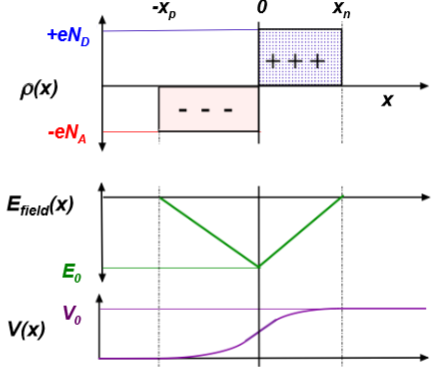
                                                                                            1. A net charge density of opposite sign remains on each side in the depletion region => Efield is generated across junction
                                                                                              1. Approximate charge density as constant on each side of depletion region

                                                                                                Anmerkungen:

                                                                                                • i.e. graph charge vs displacement is a rectangle on each side. rho = e*N_D
                                                                                                1. When diffusion and drift balance => Equilibrium => E_f is constant everywhere
                                                                                                  1. Use Gauss's Law to work out field in the depletion region

                                                                                                    Anmerkungen:

                                                                                                    • Integrate in p (-x to 0) and n (0 to x) regions separately. At interface take E = E_0. Express E_0 in terms of boundary conidtions at edges taeking and E = 0 at the edges (x_n and x_p).
                                                                                                    1. Integrate E field to get the potential
                                                                                                      1. Use boundary conditions V(x_n) = V_0 and V(x_p) = 0 to work out V in p and n (up to constant V_0) regions
                                                                                                        1. Impose continuity of V at boundary to express V_0 as function of x_p and x_n
                                                                                                          1. Use relations for x_p and x_n to express V_0 as a function of the width of the depletion region
                                                                                                            1. E_v= -eV and E_c = E_v + E_g
                                                                                                      2. Obtain expression for relative width of p and n region in terms of carrier concentrations from continuity of >E at interface
                                                                                                        1. Rearrange to get x_p and x_n in terms of width W and carrier concentrations
                                                                                                2. Operational behaviour of pn-junctions. Can bias this voltage in 4 ways

                                                                                                  Anmerkungen:

                                                                                                  • Lecture 20
                                                                                                  1. Reverse bias -V: step increases, W increases
                                                                                                    1. Zero bias. E_f is constant
                                                                                                      1. Forward bias +V: step decreases, W decreases the two E_f's are separated by eV
                                                                                                        1. Flat band V=V_0: step is 0, W=0, difference between E_f's is eV_0.
                                                                                                          1. Proof of Shockley's Ideal Diode Equation

                                                                                                            Anmerkungen:

                                                                                                            • to follow
                                                                                                            1. Calculate excess minority carriers Δp_n from difference between p_n and p_n(x_n) (same for n)

                                                                                                              Anmerkungen:

                                                                                                              • for p_n, use fermi level of n region. for p_n(x_n), use fermi level of p region. Δp_n = p_n *(exp(ev/kT)-1)
                                                                                                              1. Consider diffusion of minority carriers δp_n(X)=Δp_n*exp(-X/L_p) ,

                                                                                                                Anmerkungen:

                                                                                                                • X = x-x_n
                                                                                                                1. Hence diffusion current J_diff = e*D_p/L_p*Δp_n*exp(-X/L_p)
                                                                                                                  1. Set X = 0, so no recombination takes place. Considering both p and n diffusion currents and multiplying by area.
                                                                                                                    1. Shockley's Equation for ideal diodes: I = e*A*[D_p/L_p*p_n + D_n/L_n*n_p]*(exp(eV/kT) -1)

                                                                                                                      Anmerkungen:

                                                                                                                      • Fails for voltages above flat band. Neglects recombination within depletion region.
                                                                                                                      1. Devices
                                                                                                                        1. Forward bias
                                                                                                                          1. Diode (one-way current gate)
                                                                                                                            1. LED: recombination generates photons
                                                                                                                            2. Zero-bias
                                                                                                                              1. Photovoltaic-cells: photon absorption generates carriers which create voltage
                                                                                                                              2. Reverse-bias
                                                                                                                                1. Photodiodes: light absorbed generate carriers which generate current
                                                                                                              2. Absorption and emission in semiconductors
                                                                                                                1. TO CLARIFY: ABSORPTION COEFF'S ETC.
                                                                                                                  1. Horizontal transition (big shift in k)
                                                                                                                    1. Non-radiative: phonons
                                                                                                                      1. Phonons carry a lot of momentum, but little energy
                                                                                                                    2. Vertical transition (energy band jump)
                                                                                                                      1. Radiative: photon
                                                                                                                        1. Photons carry little momentum but a lot of energy
                                                                                                                        2. Non-radiative: multiphonons (large change in k)
                                                                                                                          1. Requires hole and electrons with same k

                                                                                                                            Anmerkungen:

                                                                                                                            • Hole and electrons have same k, so that direct transition is possible
                                                                                                                            1. For direct gap semiconductors this occurs directly
                                                                                                                              1. Direct gap s.c. suitable for optical purposes
                                                                                                                                1. Emission occurs at E_g
                                                                                                                                  1. Absorption only occurs at energies >= E_g, hence lower energies get through and show colour of material, while higher energies are absorbed.
                                                                                                                                  2. For indirect gap semiconductors requires previous horizontal transition: extremely unlikely
                                                                                                                                    1. Indirect gap s.c. not suitable for optical purposes
                                                                                                                              Zusammenfassung anzeigen Zusammenfassung ausblenden

                                                                                                                              ähnlicher Inhalt

                                                                                                                              Solid State Physics
                                                                                                                              Dinusha Senarath
                                                                                                                              Secondary storage
                                                                                                                              Zdravko Vasilev
                                                                                                                              Questions Solid State
                                                                                                                              eg612
                                                                                                                              Secondary storage
                                                                                                                              Zdravko Vasilev
                                                                                                                              Ohne Titel
                                                                                                                              eg612
                                                                                                                              Abitur Geschichte
                                                                                                                              benutzer343
                                                                                                                              Vertragsrecht - Multiple-Choice-Test
                                                                                                                              Maximilian Mustermann
                                                                                                                              Gesundheitspsychologie EC Uni Wien
                                                                                                                              hans urst
                                                                                                                              SQ3- Sei dabei! :)
                                                                                                                              B G
                                                                                                                              Vetie - Radiologie Übungs-K
                                                                                                                              Fioras Hu
                                                                                                                              PR 2018/19 GESKO VO 7-12
                                                                                                                              Adrienne Tschaudi