
Karteikarten
Option A. Sight & Wave Phenomena
Karten in diesem Stapel (37)
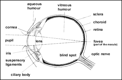
- 1A.1.1 Describe the basic structure of the human eye.
- 2A.1.2 State and explain the process of depth of vision & accommodationAccommodation is the process by which the vertebrate eye changes optical power to maintain a clear focus on an object as its distance varies.
- 3A.1.2 State and explain the process of depth of vision & accommodation (diagram)Distant Object = lens are long & thin, tight ligaments & large pupil
Near Object = lens are short & fat, slack ligaments & small pupil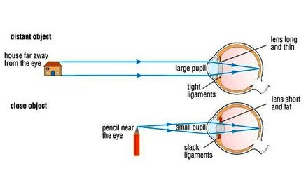
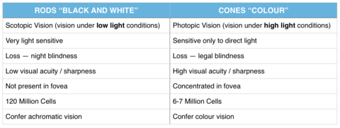
- 4A.1.3 State that the retina contains the rods and cones, and describe the variation in density across the surface of the retina.Rods - not sensitive to colour; light sensitive. Not present in fovea
Cones - Provide colour sensitivity; concentrated in fovea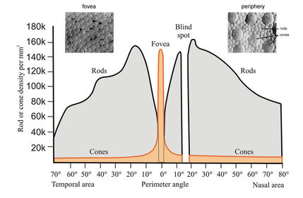
- 5A.1.4 Describe the function of the rods and cones in photopic and scotopic vision. (Spectral Response Graph)
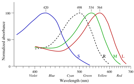
- 6A.1.4 Describe the function of the rods and cones in photopic and scotopic vision. (Table + Colour Blindness)Colour Blindness - no actual blindness, but a deficiency of colour vision. Cause is a fault in development of cone cells that transmit information to optic nerve.
- 7A.1.5 Describe colour mixing of light by addition and subtractionPrimary Colours: Red, Green, Blue
Secondary Colours:
Magenta, Cyan, Yellow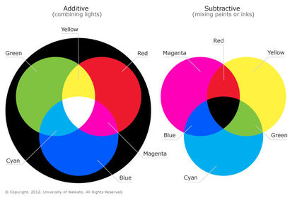
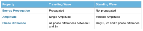
- 8A.2.1 Describe the nature of standing (stationary) waves.1.) No net propagation of energy. A standing wave does NOT move forward.
2.) Variable Amplitudes.
3.) All particles in a standing wave will either be in phase, π, or out of phase w/ each other - 9A.2.2 Explain the formation of one-dimensional standing waves.Standing waves are the result of the interference of 2 waves of EQUAL AMPLITUDE and FREQUENCY in OPPOSITE DIRECTIONS.
Nodes - Destructive Interference
Antinodes - Max Constructive Interference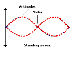
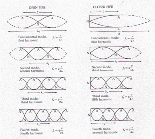
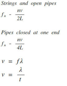
- 10A.2.3 Discuss the modes of vibration of strings and air in open and in closed pipes.
- 11A.2.4 Compare standing waves and travelling waves.
- 12A.3.1 Describe what is meant by the DOPPLER EFFECT.The change in frequency due to the movement of a source of sound or light OR
The change in frequency due to the movement of an observer in reference to a stationary source of sound or light. - 13A.3.2 Explain the Doppler effect by reference to wavefront diagrams for moving-detector situations.- Observer moves TOWARD a source, speed at which the wavefronts strike the "ear" become CLOSER
- Observer moves AWAY from a source, speed at which wavefront strike become FARTHER
(- for moving away, + for moving towards)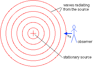
- 14A.3.2 Explain the Doppler effect by reference to wavefront diagrams for moving-source situations.- Source moves TOWARD an observer, the wavefronts get closer together b/c the source is "chasing" the previous wavefront
- Source moves AWAY from an observer, wavefronts get farther apart b/c source is "running" from the previous wavefront.
(+ For moving away, - for towards)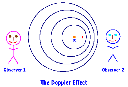
- 15A.3.5 Solve problems on the Doppler effect for electromagnetic waves using the approximationShould only be used when v <<< c.
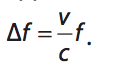
- 16A.3.6 Outline an example in which the Doppler effect is used to measure speed.- Measurement of vehicle speeds. The approximation is used only when object v is much less than the transmitter, c.
- Doppler shift occurs TWICE -- first for "moving observer" then "moving source"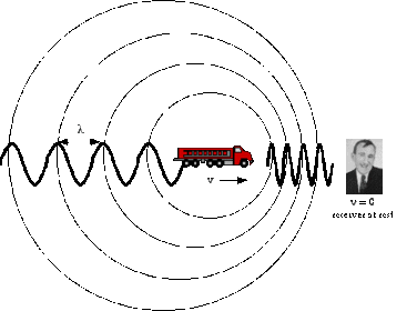
- 17A.2.5 Solve problems involving standing waves.
- 18A.3.3 Apply the Doppler effect equations for sound.f ' = new frequency
f = gen. frequency
v = velocity
v = speed of sound/light in medium
u = speed of observer/source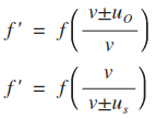
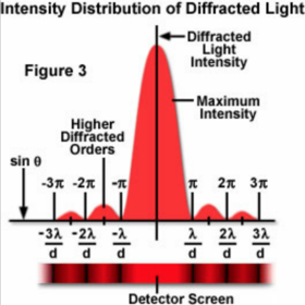
- 19A.4.1 Sketch the variation with angle of diffraction of the relative intensity of light diffracted at a single slit.
- 20A.4.1 Explain the meaning of diffraction.Diffraction is the phenomenon in which waves bend around an obstacle to pass into the region when travelling.
- 21—
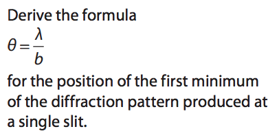
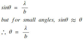
- 22A.4.3 Solve problems involving single-slit diffraction.
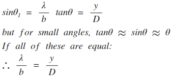
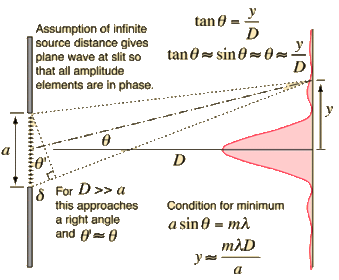
- 23A.4.3 Draw the diagram for single-slit diffraction.
- 24A.5.1 Sketch the variation with angle of diffraction of the relative intensity of light emitted by two point sources that has been diffracted at a single slit.Unresolved = diffraction patterns overlap, 2 sources appear as a single source
Just Resolved = CMOFM
Well-resolved = two sources appear as 2 distinct sources of light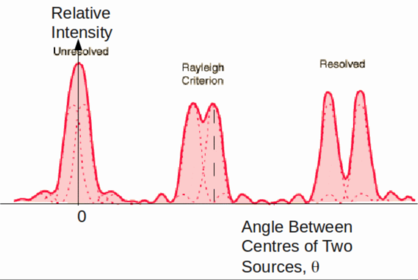
- 25A.5.2 State the Rayleigh criterion for images of two sources to be just resolved.- Just resolved: CMOFM (Central Max Overlaps First Min)
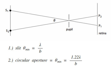
- Criterion for aperture is θ = 1.22λ/b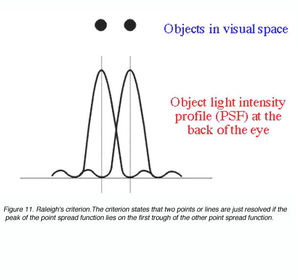
- 26A.5.3 Describe the significance of resolution in the development of devices such as CDs and DVDs, the electron microscope and radio telescopes.Electron microscopes and radio telescopes depend on good resolution to get good data.
Resolution of optical instruments can be improved by increasing its lens diameter. - 27A.5.4 Solve problems involving resolution (hint: pupil of the eyes + equation)Depending upon how diffraction patterns overlap, the person may see two sources of light appearing as only one source.
- 28A.6.1 Describe what is meant by polarized light.A LIGHT WAVE that exists in a SINGLE PLANE, especially an electric field.
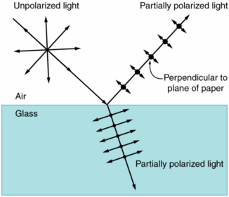
- 29A.6.2 Describe polarization by reflection. (using light or microwaves)- Light incident on a non-metallic boundary will reflect as partially / completely polarized light.
- 30A.6.2 Describe polarization by reflection. (Use of Sunglasses)- Sunglasses are used to prevent bright light or high-energy light from damaging/discomforting the eyes.
- Polarized sunglasses deflect the glare of the sun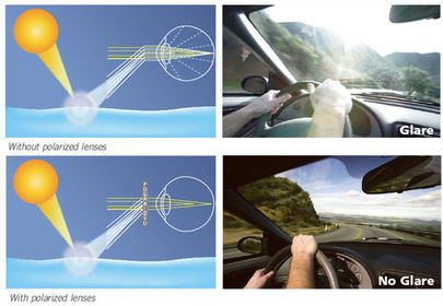
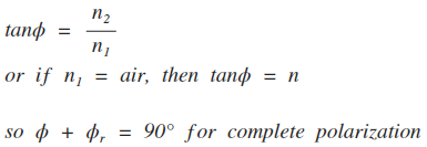
- 31A.6.3 State and apply Brewster's LawBrewster's Law: The angle at which COMPLETE POLARIZATION takes place upon reflection. (Φ - polarizing angle)
- 32A.6.4 Explain the terms polarizer and analyser.POLARIZER is a substance that passes light of a specific polarization & blocks waves of other polarizations
ANALYZER is a also a polarizer (2 polarizers placed after another), but it may be used to determine 1.) if the light is polarized, 2.) the plane of polarization. If the 2 polarizer axes are right angles NO LIGHT IS TRANSMITTED. - 33A.6.5 Calculate the intensity of a transmitted beam of polarized light using Malus’ law.When a perfect polarizer is placed in a polarized beam of light, the intensity I of the light that passes thru is given by:
- 34A.6.6 Describe what is meant by an optically active substance.One that rotates the plane of polarization of the light that passes through it.
- 35A.6.7 Describe the use of polarization in the determination of concentrations of solutions.(1) Solution placed between two crossed polaroids (liquid/chemical sol'n);
(2) plane of polarization rotated by an amount that depends on concentration;
(3) the angle rotation of second polarizer/intensity of transmitted light is a measure of concentration - 36A.6.8 Outline qualitatively how polarization may be used in stress analysis.(1) Some substances become birefringent (having 2 different refractive indices) under stress;
(2) place between 2 crossed polaroids, the stress is seen as bright and dark coloured regions;
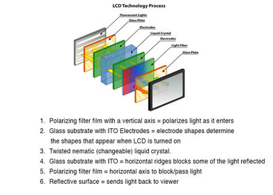
(3) the regions can be analyzed for weaknesses. - 37A.6.9 Outline qualitatively the action of Liquid Crystal Displays (LCDs).
Informationen
- Beschreibung
- IB IB Physics SL Karteikarten am Option A. Sight & Wave Phenomena, erstellt von mdabella am 22/02/2015.
- Erstellt von
- mdabella
- Aufrufe
- 48
- Tags
- Bewertung