
Mapa mental
P2.3 Currents In Electrical Circuits
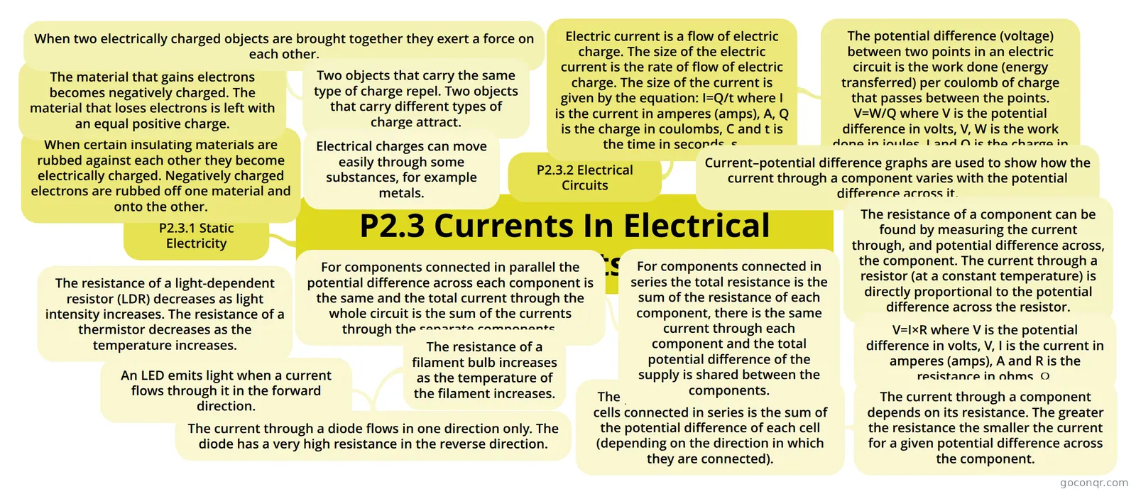
Mind map: currents in electrical circuits
Contenido del mapa
P2.3 Currents In Electrical Circuits
P2.3.1 Static Electricity
- When certain insulating materials are rubbed against each other they become electrically charged. Negatively charged electrons are rubbed off one material and onto the other.
- The material that gains electrons becomes negatively charged. The material that loses electrons is left with an equal positive charge.
- When two electrically charged objects are brought together they exert a force on each other.
- Two objects that carry the same type of charge repel. Two objects that carry different types of charge attract.
- Electrical charges can move easily through some substances, for example metals.
- Two objects that carry the same type of charge repel. Two objects that carry different types of charge attract.
- When two electrically charged objects are brought together they exert a force on each other.
- The material that gains electrons becomes negatively charged. The material that loses electrons is left with an equal positive charge.
- When certain insulating materials are rubbed against each other they become electrically charged. Negatively charged electrons are rubbed off one material and onto the other.
P2.3.2 Electrical Circuits
- Electric current is a flow of electric charge. The size of the electric current is the rate of flow of electric charge. The size of the current is given by the equation: I=Q/t where I is the current in amperes (amps), A, Q is the charge in coulombs, C and t is the time in seconds, s.
- The potential difference (voltage) between two points in an electric circuit is the work done (energy transferred) per coulomb of charge that passes between the points. V=W/Q where V is the potential difference in volts, V, W is the work done in joules, J and Q is the charge in coulombs, C.
- Current–potential difference graphs are used to show how the current through a component varies with the potential difference across it.
- The resistance of a component can be found by measuring the current through, and potential difference across, the component. The current through a resistor (at a constant temperature) is directly proportional to the potential difference across the resistor.
- V=I×R where V is the potential difference in volts, V, I is the current in amperes (amps), A and R is the resistance in ohms, Ω.
- The current through a component depends on its resistance. The greater the resistance the smaller the current for a given potential difference across the component.
- The potential difference provided by cells connected in series is the sum of the potential difference of each cell (depending on the direction in which they are connected).
- For components connected in series the total resistance is the sum of the resistance of each component, there is the same current through each component and the total potential difference of the supply is shared between the components.
- For components connected in parallel the potential difference across each component is the same and the total current through the whole circuit is the sum of the currents through the separate components.
- The resistance of a filament bulb increases as the temperature of the filament increases.
- The current through a diode flows in one direction only. The diode has a very high resistance in the reverse direction.
- An LED emits light when a current flows through it in the forward direction.
- The resistance of a light-dependent resistor (LDR) decreases as light intensity increases. The resistance of a thermistor decreases as the temperature increases.
- An LED emits light when a current flows through it in the forward direction.
- The current through a diode flows in one direction only. The diode has a very high resistance in the reverse direction.
- The resistance of a filament bulb increases as the temperature of the filament increases.
- For components connected in parallel the potential difference across each component is the same and the total current through the whole circuit is the sum of the currents through the separate components.
- For components connected in series the total resistance is the sum of the resistance of each component, there is the same current through each component and the total potential difference of the supply is shared between the components.
- The potential difference provided by cells connected in series is the sum of the potential difference of each cell (depending on the direction in which they are connected).
- The current through a component depends on its resistance. The greater the resistance the smaller the current for a given potential difference across the component.
- V=I×R where V is the potential difference in volts, V, I is the current in amperes (amps), A and R is the resistance in ohms, Ω.
- The resistance of a component can be found by measuring the current through, and potential difference across, the component. The current through a resistor (at a constant temperature) is directly proportional to the potential difference across the resistor.
- Current–potential difference graphs are used to show how the current through a component varies with the potential difference across it.
- The potential difference (voltage) between two points in an electric circuit is the work done (energy transferred) per coulomb of charge that passes between the points. V=W/Q where V is the potential difference in volts, V, W is the work done in joules, J and Q is the charge in coulombs, C.
- Electric current is a flow of electric charge. The size of the electric current is the rate of flow of electric charge. The size of the current is given by the equation: I=Q/t where I is the current in amperes (amps), A, Q is the charge in coulombs, C and t is the time in seconds, s.
Información
- Descripción
- GCSE (P2) Physics Mapa Mental sobre P2.3 Currents In Electrical Circuits, creado por killthemoment el 10/08/2014.
- Creado por
- killthemoment
- Visitas
- 108
- Etiquetas
- Valoración