
Mapa mental
Chapter 3: Input Output

Contenido del mapa
Chapter 3: Input Output
Bus structure and operation
- Bus Structure
- Communication path for the transfer of data.
- ✓ A bus is a shared communication link
- ✓ It uses one set of wires to connect multiple subsystems
- Bus Operation
- If one component wants to send/receive data to/from another component
- Request to use the bus
- Transfer the information on the bus once access is granted
- Elements of bus
- Bus types: dedicated, shared
- Arbitration methods: centralize, decentralized
- Timing: synchronous, asynchronous
- If one component wants to send/receive data to/from another component
- Advantages of Bus
- Versatility
- New devices can be added easily
- Peripherals can be moved between computer systems that use the same bus standard
- Low Cost
- A single set of wires is shared in multiple ways
- Versatility
- Disadvantages of Bus
- Creates a communication bottleneck
- The bandwidth of that bus can limit the maximum I/O throughput
- Maximum bus speed is largely limited
- Length of the bus
- Number of devices on the bus
- The need to support a range of devices
- Widely varying latencies
- Widely varying data transfer rates
- Creates a communication bottleneck
- General Bus Organization
- Data lines
- Provide a path for moving data among system modules.
- Address lines
- Used to designate the source of destination of the data on the data bus.
- The width of the address bus determines the maximum possible memory capacity of the system
- Control lines
- Use to control the access to and the use of the data and address lines.
- Data lines
- Bus Transaction
- Master
- Starts the transaction by sending address
- Slave
- Responds to the address by receiving or sending the data
- Master
- Bus Types
- Dedicated - Bus line is permanently assigned either to one function or to a physical subset of computer component
- Physical dedication associated with the use of multiple buses, each bus it is connected with only a subset of the modules.
- Bus Structure
Arbitration
- Arbitrator
- Controlling bus access by the master
- Prevent more than one bus user at a time
- Give all devices a fair chance to access the bus
- Controlling bus access by the master
- Methods
- Centralized
- Hardware (arbiter) that will grant the bus to one of the requesting devices
- Decentralized
- No arbiter, so the IO devices have to decide who goes next (no extra logic)
- Centralized
- Timing Bus
- Synchronous
- Data transfers are controlled by a handshake between the master and the slave (no common clock)
- Operations are based on two timing control lines
- Master-ready: asserted by the master to indicate that the slave is ready for a data transfer
- Slave-ready: asserted by the slave in response to the master-ready from the master
- Master-ready and slave-ready signals control the overall data transfer process (replacing clock signal in the synchronous operation)
- Advantages
- Eliminates the need for synchronization
- Accommodate varying delays automatically
- Disadvantages
- Data transfer rate is limited by two-round trip delays
- Asynchronous
- Master places the data on the bus along with the address and commands at time t0 (reference to positive edge of the clock)
- Slave strobes the data into its input buffer at time t2
- Master and slave operations are referenced to a clock
- Synchronous
- Arbitrator
Accessing I/O devices
- Multiple I/O devices may be connected to the processor and the memory via a bus
- Each I/O device is assigned a unique address.
- To access an I/O device, the processor places the address on the address lines
- The device recognizes the address, and responds to the control signals.
- I/O Devices Synchronization
- Synchronize data transfers
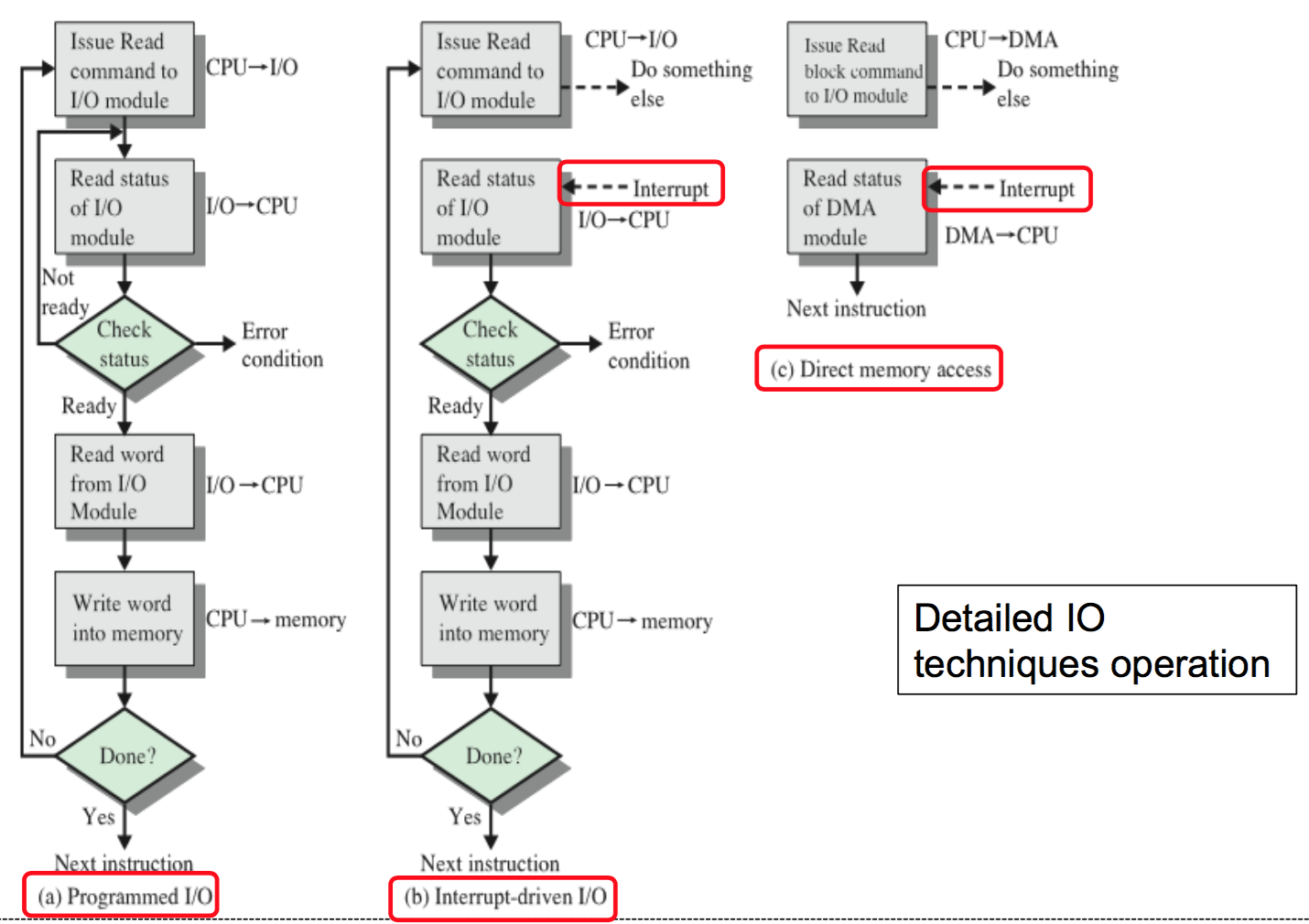
- Program-controlled I/O
- Processor repeatedly monitors a status flag
- Processor polls the I/O devices
- Processor executes a program that gives it direct control of the I/O operation
- Processor issues a command it must wait until the I/O operation is complete
- Interrupts-driven I/O
- Program-controlled I/O processor has to wait a long time for the I/O module to be ready
- I/O module interrupt the processor to request service when it is ready to exchange data with the processor
- The I/O transfer rate is limited by the speed of the I/O device
- Direct Memory Access (DMA)
- Transfer a block of data directly between an I/O device and the main memory, without continuous intervention by the processor
- Functions
- For each word, it provides the starting memory address and all the control signals
- To transfer a block of data, it increments the memory addresses and keeps track of the number of transfers
- Process
- Processor initiates the DMA transfer, then informs the DMA controller
- Starting memory address
- Number of words in the block
- Direction of transfer (I/O device to the memory, or memory to the I/O device)
- Informs the processor once transfer is completed by raising an interrupt signal
- Processor initiates the DMA transfer, then informs the DMA controller
- Operation
- Processor initiates the DMA process, supplies information to DMA controller
- DMA controller performs and manages data transfer until finished
- Interrupt the processor to notify transfer is complete
- Configuration
- Functions
- Transfer a block of data directly between an I/O device and the main memory, without continuous intervention by the processor
- Program-controlled I/O
- Synchronize data transfers
- I/O Commands
- Control: Activate a peripheral and tell it what to do
- Test: Test various status conditions associated with an I/O module and its peripherals
- Read: I/O module to obtain data from the peripheral and place it in an internal buffer
- Write: I/O module take data from the data bus and subsequently transmit that data to the peripheral
- I/O Mapping
- I/O devices and the memory may share the same address space
- Memory-mapped I/O
- Any machine instruction that can access memory can be used to transfer data to/from an I/O device
- Simpler software
- I/O devices and the memory may have different address spaces
- Special instructions to transfer data to/from I/O devices
- I/O devices may have to deal with fewer address lines
- I/O devices and the memory may share the same address space
- Summary of I/O Techniques
Interrupts
- Interrupt-request line
- I/O device alert the processor when it becomes ready
- Processor perform other useful tasks while it is waiting for the device to be ready
- Interrupt Process
- ✓ Return address, or the contents of the PC are usually stored on the processor stack.
- ✓ Processor executing the instruction located at address i when an interrupt occurs.
- ✓ Routine executed in response to an interrupt request.
- ✓ When an interrupt occurs, control must be transferred to the interrupt service routine.
- ✓ But before transferring control, the current contents of the PC (i+1), is saved in a known location.
- ✓ This will enable the return-from-interrupt instruction to resume execution at i+1.
- Interrupt Service Routine (ISR)
- ✓ This will enable the interrupted program to resume execution upon return from ISR.
- ✓ ISR may not have anything in common with the program it interrupts.
- ✓ ISR and the program that it interrupts may belong to different users.
- ✓ As a result, before branching to the ISR, not only the PC, but other information such as condition code flags, and processor registers used by both the interrupted program and the ISR must be stored.
- Interrupt Latency
- Delay between the time an interrupt request is received, and the start of execution of the iISR.
- Reduce the interrupt latency - Most processors save only the minimal amount of information
- Interrupt Acknowledge
- Inform the device that it has recognized the interrupt request
- Explicit interrupt-acknowledge control signal
- Data transfer that takes place between the device and the processor
- Inform the device that it has recognized the interrupt request
- Interrupt Enable/Disable
- Enable and disable such interruptions as desired
- Interrupt-disable
- Interrupt-enable
- Alter the intended sequence of events
- Enable and disable such interruptions as desired
- Multiple Interrupts
- Multiple interrupt requests: Multiple I/O devices connected to the processor and the memory via a bus
- Interrupt Polling
- Status register of each device has an IRQ bit that is sets to 1 when it requests an interrupt
- ISR poll the I/O devices connected to the bus
- Time consuming to query the status bits of all the I/O devices
- Priority is determined by the order in which the devices are polled.
- The first device with IRQ equal to 1 is the one that is serviced
- ISR poll the I/O devices connected to the bus
- Status register of each device has an IRQ bit that is sets to 1 when it requests an interrupt
- Interrupt Identifier
- Identify itself directly to the processor
- Sending a special code (4 to 8 bits) the processor over the bus
- Code supplied by the device represent a part of the starting address of the ISR
- Identify itself directly to the processor
- Multiple Interrupt Processing
- During the execution of an ISR of device, the processor does not accept interrupt requests from any other device.
- Priority
- Interrupt Priority
- Interrupt requests from two or more devices simultaneously
- I/O devices are organized in a priority structure
- Processor accepts the interrupt request from a device with higher priority
- - Each device has its own interrupt request and interrupt acknowledge line
- - A different priority level is assigned to the interrupt request line of each device
- Processor accepts the interrupt request from a device with higher priority
- I/O Device Priority
- An interrupt request from a high-priority device is accepted while the processor is executing the ISR of a low priority device
- A priority level is assigned to a processor that can be changed under program control
- Processor's Priority
- Encoded in a few bits of the processor status register
- Priority can be changed by instructions that write into the processor status register
- Privileged instructions: Instructions that can be executed only in the supervisor mode
- Encoded in a few bits of the processor status register
- Interrupt Priority
- Interrupts Mechanisms
- Each interrupt-request line is assigned a different priority level
- Devices share the interrupt-request line, and interrupt-acknowledge line is connected to form a daisy chain
- Devices are organized into groups and groups have different priority levels. All the devices within a single group share an interrupt-request line, and are connected to form a daisy chain.
- Interrupt Request Control
- Interface circuit of each I/O device has an interrupt-enable bit
- Generate an interrupt request
- Interface circuit of each I/O device has an interrupt-enable bit
- Exceptions
- Any event that causes an interruption
- Interrupt-requests from I/O devices
- Recovery from errors
- Debugging
- Analyzing Exceptions
- Trace mode
- Exception occurs after the execution of every instruction
- Breakpoints
- Exception occurs only at specific points selected by the user
- Trace mode
- Analyzing Exceptions
- Privilege exception
- Execute a privileged instruction in the user mode
- Processor to switch to the supervisor mode
- Execution of an appropriate exception-servicing routine
- Execute a privileged instruction in the user mode
- Any event that causes an interruption
- Exception Sources
- Sources of errors in a processor
- Error in the data stored
- Error during the execution of an instruction
- Exception processing
- Processor takes the same steps as in the case of I/O interrupt-request
- Suspends the execution of the current program, and starts executing an exception-service routine
- Sources of errors in a processor
- I/O Interrupt VS Exceptions
- I/O Interrupt
- Completes the execution of an instruction in progress
- Exceptions
- Execution of an instruction in progress usually cannot be completed
- I/O Interrupt
- Interrupt-request line
Interface circuits
- Circuits
- I/O interface consists of the circuitry required to connect an I/O device to a computer bus
- Side of the interface
- Computer
- Bus signals for address, data and control
- I/O device
- Data path and associated controls to transfer data between the interface and the I/O device
- Computer
- Side of the interface
- I/O interface consists of the circuitry required to connect an I/O device to a computer bus
- Parallel/Serial Ports
- Parrallel
- Transfers data in the form of a number of bits at a time
- Serial
- Block Diagram
- Interface circuit for serial port
- Characterictics
- Require fewer wires
- Connecting devices that are physically distant from the computer
- Bit rate
- Speed of transmission of the data over a serial interface
- Range of clock speeds
- Accommodate devices with a range of speeds
- Standard serial interfaces
- UART for low-speed serial devices
- RS-232-C
- Require fewer wires
- Connect the processor to I/O devices that require transmission of data one bit at a time
- Transfers and receives data one bit at a time
- Communicates in a bit-serial fashion on the device side and bit parallel fashion on the bus side
- Block Diagram
- Parrallel
- I/O Interface Block Diagram
- Functions
- Register for temporary storage of data
- Status register containing status information
- Control register that holds the information governing the behavior of the interface
- Contains address-decoding circuitry to determine when it is being addressed by the processor
- Generates the required timing signals
- Performs format conversion (communication protocol) – necessary for data transfer to/from the processor
- Input Interface
- Keyboard
- Processor Side
- Data lines
- Address lines
- Control or R/W line
- Master-ready signal
- Slave-ready signal
- Keyboard Side
- Encoder circuit
- Debouncing circuit
- Data lines
- Valid line
- Processor Side
- Keyboard
- Output Interface
- Printer
- Processor Side
- Data lines
- Address lines
- Control or R/W line
- Master-ready signal
- Slave-ready signal
- Printer Side
- Idle signal line
- Processor places a new character into a DATAOUT register
- Valid signal
- Processor Side
- Printer
- Circuits
Interconnection standards
- The Need of Standards
- I/O device is connected to a computer using an interface circuit
- Interfacing is easier
- I/O device is connected to a computer using an interface circuit
- Motherboard Bus
- Provides another bus that can support more devices
- Processor bus and expansion bus are interconnected by a circuit called “bridge
- Devices connected to the expansion bus experience a small delay in data transfers
- Provides another bus that can support more devices
- Bus Standards
- PCI (Peripheral Component Interconnect)
- PCI Connection in Computer
- PCI Bus
- Parallel interface connection
- Function: Support memory transfers involve a burst of data rather than just one word
- Advantages
- Low-cost bus
- Processor independent
- Plug-and-play capability
- I/O Devices using PCI
- Graphic card/GPU
- Sound card
- High performance FPGA board
- PCI Concept
- The bus supports three independent address spaces: memory, I/O, and configuration
- Master is called an initiator
- Slave is called a target
- PCI Pins List
- Address and Data Signals
- AD[31:00]
- Address and data are both multiplexed on the same PCI pins
- PCI supports both single and burst read and write transactions
- C/BE[3:0]#
- 4-bit command/byte enable bus
- Defines the PCI command during address phase
- Indicates byte enable during data phases
- PAR
- Parity bit: Verify correct transmittal of address/data and command/byte-enable
- AD[31:00]
- Interface Control Signals
- FRAME#
- Initiator start and end of a transaction
- TRDY#
- Target ready to send or receive data
- IRDY#
- Initiator ready to send or receive data
- STOP#
- Target terminate the transaction
- DEVSEL#
- Individual device select for configuration
- IDSEL
- Device select: Target decoding the address associated with each transaction
- FRAME#
- Arbitration Signals
- REQ#
- Initiator to request bus ownership
- GNT#
- System arbiter to grant bus ownership to the initiator
- REQ#
- Interrupt and System Signals
- INTA#/B#/C#/D#
- Interrupt A/B/C/D is used to request Interrupts
- CLK
- PCI operates at 33 or 66 MHz
- RST#
- Asynchronous reset
- INTA#/B#/C#/D#
- Address and Data Signals
- PCI Operation
- Read
- Write
- PCI Commands
- PCI Variations
- Same protocol format, but in a different form factor
- PMC: PCI Mezzanine Card
- Compact PCI: PCI in Eurocard form factor
- Mini PCI: For laptops
- Same protocol format, but in a different form factor
- USB (Universal Serial Bus)
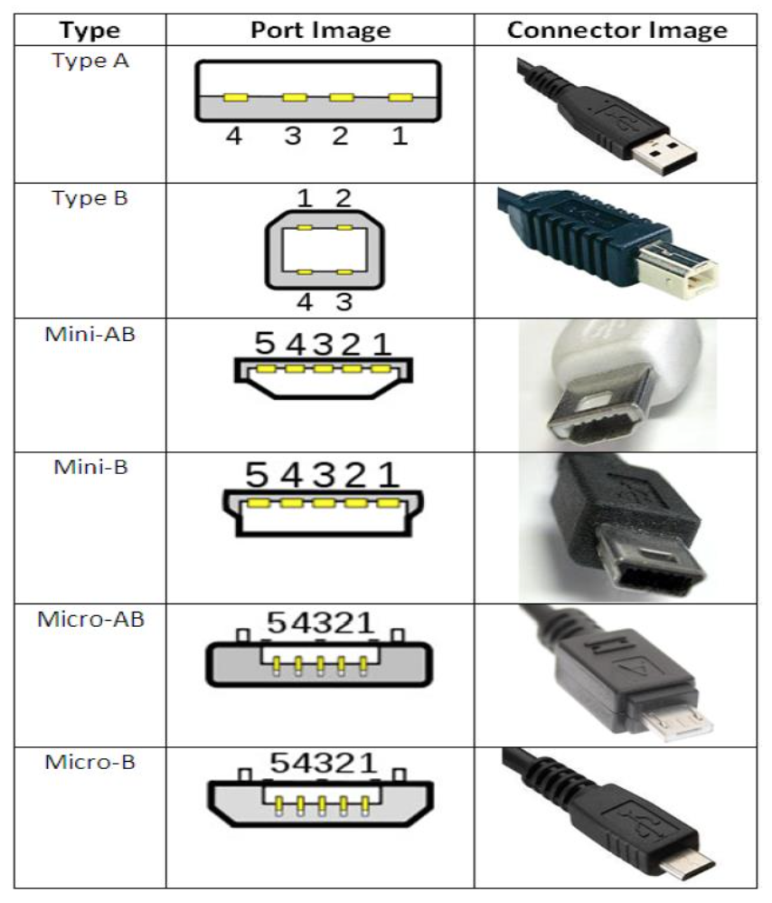
- USB Physical Pins
- USB Variations
- USB Tree Structure
- Accommodate a large number of devices that can be added or removed at any time
- Each node of the tree connected to a hub, acts as an intermediate control point between the host and the I/O devices
- USB Operation
- Hub copies a message that it receives from its upstream connection to all its downstream ports
- USB enables the host to communicate with the I/O devices, but it does not enable these devices to communicate with each other
- USB Adressing
- USB is connected to a host computer, its root hub is attached to the processor bus, where it appears as a single device
- Host software communicates with individual devices attached to the USB by sending packets of information,
- Each device on the USB, whether it is a hub or an I/O device, is assigned a 7-bit address
- This address is local to the USB tree
- USB Protocol
- Information transferred over the USB
- Organized in packets
- Consists of one or more bytes of information
- The first field of any packet is called the packet identifier (PID)
- PID are transmitted twice
- First time they are sent with their true values
- Second time with each bit complemented
- PID are transmitted twice
- The first field of any packet is called the packet identifier (PID)
- Control Packets
- Addressing a device to initiate data transfer
- Acknowledging that data have been received correctly
- Indicating an error
- Data Packets
- Carry information that is delivered to a device
- Consists of one or more bytes of information
- Organized in packets
- Information transferred over the USB
- USB Data Transfer
- PCI (Peripheral Component Interconnect)
- The Need of Standards
Imágenes y archivos del mapa




Información
- Descripción
- Mapa Mental sobre Chapter 3: Input Output, creado por ap peter el 10/11/2018.
- Creado por
- ap peter
- Visitas
- 0
- Historial
-
- Creado por ainan nuha · 11 oct 2018
- Copiado por ap peter · 10 nov 2018
- Valoración