
Description
Annotations:
- Is a human activity that involves the activities: analysis, design, implementation and testing that leads to produce a software system. To obtain a high quality software product requires a well-managed development process. So project management is a necessary activity within the discipline of software development.
- System boundary (scope of a system)
Annotations:
- Conceptual line that divides the system from ‘everything else’
- Software
Annotations:
- Collection of programs and related data that provide instructions to tell computer what to do.
- Software Engineering
Annotations:
- concerned with the theories, methods, and tools, which are needed to develop reliable, efficient and economically software on real machines, and meet changing requirements, using engineering principles
- Common Characteristics
Annotations:
- -Meeting a clear set of requirements -Use a defined process with clear activities, each of which has at least one identifiable end-product; -Can apply their skills and experience to the tasks demanded of them; -Regard validation and verification to be as essential as building the software itself; -Make sensible use of tools and standards.
- -Meeting a clear set of requirements -Use a defined process with clear activities, each of which has at least one identifiable end-product; -Can apply their skills and experience to the tasks demanded of them; -Regard validation and verification to be as essential as building the software itself; -Make sensible use of tools and standards.
- Legacy systems
Annotations:
- -Usually large -Critical to the business; -Changed a number of times -Difficult to understand -Difficult to maintain -Lacking in flexibility,
- System
Annotations:
- Assembly of components connected together in organized way.
- System’s Environment
Annotations:
- Made up of things not part of the system, but either affect the system or be affected by it.
- Domain
Annotations:
- is a particular area of interest.
- Characteristics of software that affect its Development
Annotations:
- Risks affecting Large projects: 1.If the size of a project is increased, errors are also increased. 2.In large projects, the number of team members is also large and this may lead to the following risks: -Effective communication more difficult-Developers have no experience of the problem domain
- Malleability:
Annotations:
- Easy to change, changed rather than replaced.
- Complexity:
Annotations:
- complexity is increased, errors will be increased.
- Size
Annotations:
- more errors in a large piece of software
- Modularization
Annotations:
- Decompose system or problem to a smaller sub-system with separate boundaries (modules)
- Projection:
Annotations:
- Pependent Modules,
- Partitions:
Annotations:
- Independent Modules
- Coupling
Annotations:
- Refer to the degree of inter and or circular dependence among different modules, good software is loosely coupled system, which is easier to understand, modify, replace and reuse.
- Object-Oriented
Annotations:
- two classes need to be coupled in order to allow any communication between their instances. The class A is coupled to the class B if any of the following applies: -A inherits from B; -A has an attribute of class B; -A has a method that uses an instance of class B as an input or output argument; -A knows of a public attribute of class B. A module which provides a service may require other services from another module, the required services are called context dependencies
- Cohesion
Annotations:
- Activities within a single module are related to each other A high cohesion module performs one task or achieves a single objective. Low coupling and high cohesive are competing. A developer should try to achieve the best balance between the levels of coupling and cohesion.
- Software- System Architecture
Annotations:
- The structure of the items that make up software system It includes: -Responsibilities for items; -Their interconnections; -Appropriate Technology
- Main activities SW Development Process (Life cycle of SW Development )
- Analysis Requirement Engineering
Annotations:
- Requirement Engineering: The process of reaching an agreed set of requirement and gaining enough understanding of the problem. Requirements: Functions and qualities we want of a product.
- Requirements Elicitation
Annotations:
- Where the developer discovers, identifying, understand requirements and review the users needs and the potential constraints on both software system and the development activities. This is done by: -consulting the stakeholders, -reading existing documents, -understanding the domain, -defining the boundaries of the system, -understanding the possibilities for change. There are many techniques for elicitation: -interviewing, -brainstorming, -running focus groups, -holding team meetings. -There are also modeling techniques to help this process (e.g. activity diagrams, use cases).
- Requirements need to be
Annotations:
- 1.Necessary and traceable: each requirement should fulfil a purpose, and it should be clear where each requirement comes from; 2.Non-ambiguous and realistic: there should be no alternative interpretations for a requirement, and it should be feasible to carry each requirement through to development; 3.complete: all the intended functionality should be described as much as possible; 4.consistent: requirements should not contradict each other; 5.verifiable: it should be possible to check that a requirement has been implemented; 6.independent of design, avoiding design decisions that are not relevant at this stage. However avoidance of all design issues is not always practical
- Requirements Dependencies
Annotations:
- Need to be investigated at this stage of the software development life cycle. A practical approach for investigating the dependencies between requirements, is to consider a few representative scenarios from a set of all the possible scenarios that illustrate the requirements in practice
- NFR
Annotations:
- A non-functional requirement is a requirement about a quality that the product must have. Examples of NFR: ◦ X must validate the user’s identity and password within 3 seconds: ◦ X must be usable by users with limited skills. ◦ X must operate in arctic climates (freezingweather). ◦ X must work fast, secure, etc. Usually NFR are associated with FR in requirements document, and you need to distinguish between them. You can think of non-functional requirements is as constraints on the functional requirements. To have useful NFR, NFR must be testable (measurable) as well as FR. In this respect the idea of fit criteria is introduced.
- Security
Annotations:
- Security covers confidentiality, integrity and availability (often abbreviated to CIA), and is concerned with threats against assets. ◦ Confidentiality refers to the protection of data from unauthorized access and disclosure.◦ Integrity refers to consistency of data. ◦ Availability refers to access by authorized users. Computer security is concerned with the detection and prevention of unauthorized actions by users(intruders) of a computer system. Some examples of intruders are: ◦‘hackers’ who test their skills against the security measures of a system for their personal pleasure; ◦Competitors who may try to gain access to commercially secret information; ◦Fraudsters who try to obtain financial gain from the owner of the system or some third party. You can protect your own PC by physical means: ◦Placing the computer in a room to which only certain people have (physical) access. ◦Providing authority to certain individuals to do specific tasks ◦Providing user name and password for accessing the system.
- In a distributed computing system, which involves a number of interconnected computers, some security problems arise: 1.Someone being able to intercept, read or alter users’ communications. -This interception may be passive (just listening to the communications) or active (listening and retransmitting the messages with or without changes).2.on an external network, communications will pass through many third-party systems with unknown security measures, which cannot be controlled.In a distributed computing system, security becomes a major issue. Ex. : Ecommerce distributed computing system using internet.Usually a firewall is used to protect networks.
- The forms of attack a system may face: 1.Disclosure (of confidential information) or the unauthorized release of information (e.g. an intruder steals credit card information / reads your messages). 2.Modification or the unauthorized alteration of data (e.g. an intruder may change messages or stored data). 3.Denial of use or service, where there is some denial of network service to its authorized users (e.g. an intruder redirects your messages or gain control of the computers owned by innocent third parties and use these computers to bombard your site with messages). 4.Repudiation, where a legitimate user claims that they did not send or receive a particular message that was sent or received.
- Legal
Annotations:
- concern with two important areas from which requirements must be elicited are the law and the standards that apply to the product . A third area related to law is the regulatory structure that controls some industries. The cost of litigation is one of the major risks for commercial software, and can be expensive for other kinds of software. ◦ There are penalties for non conformance with the law: fines, imprisonment and loss of reputation.
- Cultural & Political
Annotations:
- Cultural requirements usually arise: 1. When a company attempts to sell a product in a different country, with a very different culture and/or language; 2. When eliciting requirements in an organization different from one’s own. ◦ One need to seek the help of someone who is knowledgeable about the culture. ◦ An example of a cultural requirement: - The language used in the interface should be formal and polite. Political requirements is a requirement for which someone is unwilling or unable to provide a coherent rationale. A political requirement is often stated in terms of ‘I want it’.
- Maintainability&Portability
Annotations:
- Maintainability requirements concern with two issues: 1. Keeping the product updated in the light of expected changes. 2. Fixing the product when it fails. Portability requirements concern the need to port the software to new hardware/software environments at some later stage. Examples of maintainability and portability requirements: ◦ The product shall be able to be modified to cope with a new class of a user. ◦ The product shall be able to be modified to cope with minor changes to European law that occur every six months on average. ◦ The product shall be portable to all of the operating systems currently used in our Slough office.
- Operational
Annotations:
- Describe the operational environment (external factors). This involves requirements related to the installation of the product and the needs of the installers. Examples of operational requirements: ◦ The product shall be usable at altitudes up to 1500 m, in icy and wet conditions, and in both darkness and extremely bright sunshine. ◦ The product will be used in a standard office environment, except that high levels of background noise may occur. ◦ The product will need to be installed at 58 locations around the proposed route of the race in 2 days by 3 semi-skilled workers. Note that: performance requirements deal with internal factors related to a product such as: security, speed, and size. While operational requirements concern about external factors related to the environment of operation.
- Performance
Annotations:
- Relate to the capacity of a system to carry out its tasks. This includes: a. the speed with which the system should operate; this could be influenced by the number of transactions or amount of data it is able to process in a given time. (throughout and volume); b. capacity: how much data or information it can handle; c. accuracy : how accurately in can produce its results; d. reliability: the ability of the system should operate correctly, produce the same results and do the same thing each time under the same conditions. Examples of performance requirements: ◦ The product shall calculate a guest’s bill in 2 seconds. ◦ The product shall handle up to 10 users simultaneously. ◦ The product shall, on average, operate without failure for 20 days.
- Usability
Annotations:
- The product’s ease of use, and any special usability considerations; Can be split into two requirements: 1. An Easy to learn requirement: is contextual - no training is needed before using as online reservation websites - some may need months before user can use it such as: nuclear-reactor control system. - Example: A university graduate should be able to learn to use 50% of the functionality of the product in 2 hours. 2. An easy to use product: Example: 90% of the population should be able to place an order from a web interface within 5 minutes.
- Look&feel
Annotations:
- Look-and-feel requirements: the spirit of the product’s appearance; describe the overall appearance and behavior of the product to its users. It is not about a specific design of the user interface This is of designer’s responsibility . It is concerned with the impression we wish to make; we want it to reflect the distinctive values, ethos and style of our organization. Examples of look-and-feel requirements: ◦ The product shall comply with the Motif user-interface guidelines. ◦ The product shall use only two colors. ◦ The product shall use lots of animation. ◦ The product shall use a large range of exciting sounds.
- Fit Criterion
Annotations:
- A fit criterion is a measurement of a requirement that will ultimately enable a tester to determine whether or not the delivered product satisfies, or fits, the requirement. Benefits of attaching fit-criteria to requirements: ◦Helps to clarify the requirement; ◦Helpful communication tool for interacting with different stakeholders to check that the criteria being specified are acceptable and reflect the correct understanding of the requirement. The fit criteria can be written or elicited as the requirements are elicited. The parties that need fit criteria are:◦The developers of the product use the fit criteria to develop the product to meet those criteria.◦The testers use the fit criteria to determine whether the delivered product meets the original requirements.◦The clients for whom the product is being developed use the fit criteria as acceptance criteria for the product.A fit criterion for a functional requirement specifies the completion of the function of the product. Example 1: FR fit criteria◦FR: send an email to the student after a marked TMA has been uploaded by the tutor,◦Fit criterion: an email should indeed be sent to the student and reflected in their mailbox on the forum. Example 2: FR fit criteria◦FR: The system shall accept a credit card number from a client.◦Fit criterion: A valid credit card number has been stored in the system. A fit criterion for a non-functional requirement specifies a value or values, on a particular scale of measurement, that must be attained by the property or quality with which the requirement is concerned. Example 1: NFR fit criteria◦NFR : The credit card number should be accepted securely.◦Fit-criteria: The credit card number should be revealed to a third party in less than 0.0001% of cases. Example 2: NFR fit criteria◦NFR: The credit card number should be accepted within five seconds.◦Then this statement contains its own fit criterion, as it is already expressed in terms of the quantity time. Example 3: Usability requirementFor a public information kiosk (booth) at a railway station, the usability requirement is as follows:◦Description: The kiosk shall be usable by a member of the public who may not speak or read English. One possible fit criterion is as follows:◦Fit criterion: 15 out of 20 non-English speakers/readers shall be able to use the kiosk without either referring to the online help or walking away without the desired information.You can find more examples in the course notes.
- FR
Annotations:
- Describes the behavior of the system. -Specifications of the product’s functionality; -Derived from the fundamental purpose of the product; -Actions that the product must take, check, calculate, record, retrieve etc (verbs are functions); - Not a quality; For example,‘fast’ is a quality, and is therefore a non functional requirement ( Adjectives talks about quality )
- The steps to eliciting functional requirements: 1. Understand the domain, determining the business processes that rare triggered by business events. 2. Determine the scope of the new system, and which business events are relevant. 3. Draw up a set of use cases for the product associated with those events. 4. Describe each use case by one or more scenarios – sets of steps. 5. Work through each step of each scenario to determine a set of system requirements. 6. Check for similar requirements from different use cases. 7. Search out and remove ambiguity.
- Technical Solution Requirements
Annotations:
- is a constraint on the product due to the technology of the solution that must be adopted. - Specific technology is mandated. X must check a user’s password X must employ the company’s password maintenance system.
- Business Requirement:
Annotations:
- - The requirement states what needs to be done, not how to do it. - Tasks that system should do Examples: X must check a user’s identity. X must produce a statement of the user’s account.
- Prototype
Annotations:
- Prototyping the user interface brings developers and users into close contact with each other. By working together it is possible to minimise any misunderstanding that might lead to false expectations on either side. - One way to improve the analysis and identification of requirements and reduce the risk of requirements which is identified incorrectly, is for the developers to produce a prototype. - A prototype is not a completed working version of the software. - Prototype can take several forms: -mock-up of the human–computer interface for a specific group of users. - Working version of a subset of the functions required from the eventual product; - Existing piece of software that has some relevance to the users’ needs and needs further improvement
- Domain expert
Annotations:
- To decide if the model built is adequate for the purpose you need a domain expert. ◦ Domain expert: person who understands the relevant part of the application domain rather than the technology used to automate it.
- Inputs
Annotations:
- 1.Information from the stakeholders’ needs; 2.Information from existing knowledge of the domain and associated regulations, the organization's standards, and any systems that are already in place.
- Outputs
Annotations:
- 1.The main output is the contract between the customer and the developers of the system. 2.The requirements document and the models of what the system is intended to do. -The requirements document includes the requirements specification that contain the precise and accurate descriptions of each requirement. We use our Natural Language (NL) to describe and write requirements. -Our language is ambiguous, and some sources of ambiguity in NL are: ◦ Using pronouns (it, their, etc.) ◦ a word may have multiple meanings, or can be interpreted in different ways by different people. -To solve such ambiguity: ◦ Avoid using pronouns. ◦ Record the abbreviations, and definitions for words that have technical meanings or meanings specific to the business. How to write requirements document? ◦ Write clear unambiguous statements; ◦ Statements may also need to be constrained in other ways; ◦ Requirements should be described at a level of detail that the people ordering the system (customer) can understand; - Write abstract statements for the users that is used to communicate with stakeholders (user requirements) - Write detailed description of the functionality to be used by designers (software requirements). # Requirements specification is the activity of translating the information gathered during the analysis activity into a document that defines a set of requirements. - This document includes two types of requirements: user requirements and software requirements.
- Requirements Analysis and Negotiation,
Annotations:
- - Is the activity where requirements are categorized and prioritized, and examined for their properties of consistency, completeness and non-ambiguity. - Models of requirements are created to help communication with the customers and developers.
- Business
Annotations:
- Understanding the business is important step in SW Development it's the context in which software system will be applied
- Business Rules
Annotations:
- Business Rules: Constrain how a business is run, Business rules govern the functioning of a business, and business processes, define the activities that take place, their ordering and the roles required to carry them out. Need to identified and recorded : -To provide quick east access whenever there is a change -Basis of decision making # Should support the Business Processes and strategy # Should be represented independently of other models to facilitate analysis # in well defined and structured language # Possible traceability # Ant
- Business Processes
Annotations:
- The activities that manipulate, transform and use these resources. Business processes can be represented by activity diagrams. what is done in business by who in what order needing which resources and what consequences it important to understand what business done
- Business Resources
Annotations:
- People, Product, Info, and materials
- Business Goals
Annotations:
- that define the purpose of the business
- Requirements Documentation
Annotations:
- Requirements need to be documented within a project.Requirements documentation is usually done using a template document. Records decisions; it is the main reference for what should be built, and the basis for validation of the built system. This document includes two types of requirements: user requirements and software requirements -The one we adopt here is based on the Volere template by Robertson and Robertson (2006).The Volere template is a template for a document that collates all the requirements of a system. - The template provides a sort of container, in which the information can be organized systematically.- it is the main reference for what should be built, and the basis for validation of the built system.The Volere template is organized into four main sections each including a number of requirements categories: ◦Product constraints ◦Functional requirements ◦Non-functional requirements ◦Project issues Functional and non-functional requirements are the core of the requirements document. Information recorded for each FR/NFR: ◦Requirement number – a number uniquely identifying the requirement;◦Events/use cases – the use cases or events that are associated with this requirement;◦Description – a one-sentence statement of the intent of the requirement;◦Rationale – a statement of why the requirement is considered important or necessary;◦Source – a record of who raised the requirement in the first instance;◦Fit criteria – acceptance criteria, written in a quantified manner so that the solution can be tested against the requirement;◦Dependencies – the identifying numbers of other requirements that have an impact on this one;◦Conflicts – the identifying numbers of requirements that contradict this one, or make this one less feasible;◦History – the origin of the requirement, and any changes to it.
- Requirements Validation
Annotations:
- Requirements validation consists of a careful check of the overall requirements documentation, usually following a checklist of questions. This is a way of ensuring that the requirements are of sufficient quality.
- Design:
Annotations:
- How will you solve the problem To move toward design and using interaction diagram that reflect behavior of the system you have to do the following: 1. Start from use cases: take each scenario, in cooperation with class model to determine methods of each class and scenario to show you flow of messages, which lead you to build sequence diagram. 2. A most important point, is where the initial message come from, usually the interface is used to initiate first message. 3. The aim of interaction diagram is to determine exactly all operations and its classes, you can use association with role names found in class model, and manipulation them as methods in classes based on association direction.
- Modeling
Annotations:
- Modeling: is a way of thinking about things and ideas in the 'real world'. A model, in terms of software development, is an abstract representation of a specification, a design or a system, from a particular point of view. It is a simplification of reality, created in order to understand an aspect of the system in question. A good model concentrate on the essentials of a complex problem by keeping out non-essential details. In Software development, models are: -A way of understanding the problems involved. -An aid to communicate especially between developers. -A component of the methods used in development activities such as analysis and design. During SW development, you will be interested in different aspects or views of the problem and its solution at different times. This implies constructing different models
- It is better to use standard notation in modeling throughout SW development process i.e. modeling language. A modeling language is based on diagrams and their construction, meaning and use. There are two rules within a diagram based modeling language: 1. Syntax: determine what diagrams exist and what symbols are used for. 2. Semantic: what these symbols mean.The modeling language you select must:1. Allows to express many facets of the subject. 2.Helps you to resolve misunderstanding rather than introducing new ones. 3.Is easy to learn and use.4.Is supported by tools. 5.Is used widely and accepted in industry.
- Throughout the SW development, the following 7 models are produced:
- UML
Annotations:
- The Unified Modeling Language (UML): is a standard modeling language, which is diagrammatic, but also allowing developers to add text, and is easy to use, efficiently expressive, unambiguous, widely used and supported by tools. Using a standard modeling language is important: 1.It helps when new people join a project. It reduces the time needed to enable them to become productive team members. 2.It is likely that project components will have been constructed using that language. This makes the software easier and cheaper to maintain.
- Static Behaviour Model
Annotations:
- Describes objects and their relationship
- Use Case Diagram
Annotations:
- Help you to define what a proposed system should do from a user’s perspective.. - is something that actor needs to do with system help represented in UML- Can also provide a basis for a contract between the customer and the developer-The requirements of a use case can be captured through either a written statement or, more formally, the use of Pre and Post conditions; - Detailed software requirements can be generated from each step of a scenario of a use case; - a use case can be ‘walked through’ by one or more scenarios, which are particular sequences of possible actions within a given use case.- Must contain the following parts : -Use Case Identifier and name-Initiator -Precondition -Postcondition -Main Success Scenario-Goal
- scenario
Annotations:
- Is a specific sequence of activities that might occur when a system is used.
- Actor
Annotations:
- User of system - external - : Human or other system
- «include»
Annotations:
- The «include» relationship shows how a subsidiary use case can provide some common functionality to two or more use cases at a higher level of abstraction and how the system can employ a pre-existing component
- «extend»
Annotations:
- The «extend» relationship between a new use case and an original use case shows how the system should deal with conditional behaviour.
- Activity Diagram
Annotations:
- # Show process as a set of activity showing their sequence and where activities can be carried out in parallel # Can extend to show responsible person # Help investigate Workflow of Control from one activity to another #Can Record scenario of use cases # Activity diagrams are a way of understanding the workflows within the business domain. They allow you to record the things that users do or want to do. From a simple problem description, you can show the flow of control between the activities that are carried out by a role. # Activity modelling can help identify when the user would need to use an interface to the proposed software system You can use activity diagrams for any of the scenarios of a use case where some interaction with an actor is expected.
- Class Diagram
Annotations:
- Is a static model that describes the objects and the relationships that are needed between them to implement the required functionality indicates which classes are in the system and describes the associations between those classes. describes what is true about the entire system at all times. expresses a generalization of all possible object diagrams indicates what possible connections can exist. is visually represented using a class diagram A class diagram: is a visual representation of a class model. It represents what all possible instances of the class have in common, rather than the particular values of any given instance. The main aim of using a class diagram in a conceptual model is: ◦ to represent the information that exists in the problem domain including: classes, their properties as attributes and their relationships as associations. A class diagram consists of boxes representing classes, and lines representing associations. A box may contain up to three different parts: 1. A class name 2. Attributes 3. Operations (don’t appear in object diagram.)
- The search for classes The FIRST step in building a class model is to identify objects in the problem domain We look first for objects because objects are instances of the classes, they are an excellent source of candidate classes. The following categories are useful sources of relevant objects:◦ Tangible objects: the physical things in the domain such as rooms, bills, books and vehicles; ◦ Roles: the roles played by people in the domain, such as employees, guests and members; ◦ Events: the circumstances, episodes, interactions, happenings and significant incidents, such as room reservations, vehicle registrations, orders, deliveries and transactions; ◦ Organizational units: the groups to which people belong, such as accounts departments, production teams and maintenance crews. To identify candidate classes, a list of nouns makes an excellent starting point. A lot of nouns appear in the documents, so you need to filter them by three criteria as follows: 1. Redundancy: the same concept is often given different names; and you should rename them appropriately; 2. Not important or independent enough, such as an attribute of another class rather than a class in its own right; 3. Lack of relevance to the problem domain; e.g. beyond the scope of the desired system, or part of the language used for modeling.
- Class
Annotations:
- A class usually have properties that are important such as: ◦ Attributes: properties of objects ◦ Associations: properties represent relationship between classes A class describes all possible objects of that type, defining what the objects have in common. Attributes of a class do not have values, but instead indicate the values that instances of the class may have. A class describes what is true about all objects of that class at all times
- Object Diagram
Annotations:
- An object model: is a collection of objects, where every object in the model is an instance of a class in the class model. it represents a snapshot of the system at one instant in time. no object can have attributes or relationships that are not in the class model. an object model may be thought of as an instantiation of a class model. shows concrete instances of relevant classes & relationships. indicates what connections do exist at that instant in time. is visually represented using an object diagram. An object diagram: is a visual representation of an object model, showing a snapshot of the system at some point in time. Why do we need Object diagrams? 1. Checking your understanding of concepts and relationships. 2. Pairs of them can be useful in showing the system before and after performing some operation. 3. They are a fruitful source of special cases where requirements are not precisely clear. An object diagram cannot express general structure properties so we need a class diagram.
- The elements of this object diagram are: ◦ Rectangular boxes representing objects. Inside each box you add ObjectName : ClassName which are underlined. Names and values of useful attributes in a second compartment (Optional) ◦ Lines drawn between objects are called links. They represent particular cases of one object ‘knowing about’ another object. Each link is an instance of an association (a relationship between classes).
- Object
Annotations:
- An object stands for something real in a domain expert’s world. E.g. a specific customer; a specific room in a hotel An object is considered as an instance of the class. The attributes of an object have values that can be tested. Identity: every object has a unique identifier that does not depend on the current value of any of its attributes, or even on what class it is.
- Associations
Annotations:
- Associations are relationships between two types. UML defines an association to be a semantic relationship between two types (classes) that connects their instances (objects).
- Multiplicities
Annotations:
- Multiplicity determines how many objects are involved in a given relationship. Each end of an association has a multiplicity. By stating a multiplicity, you are saying how many instances (objects) of one class can be linked with a single instance (object) of a class at the other end of the association. If labels are added to the ends of associations, then they are role names.
- names and role names
Annotations:
- UML provides two mechanisms for naming associations: 1. Using role names Role names allow you to name the ends of associations. The name you give to one end of an association depends on the purpose, or role, of the association from the point of view of the object at the other end. 2. placing an association name in the middle of the association line: Association names are usually verbs. UML allows a little black triangular arrowhead to be added to the association name to indicate direction of reading
- Qualified association
Annotations:
- qualified associations are a way of capturing the uniqueness of some manner of identifying objects, as in the case of account numbers in a bank. Suppose that one of your classes has an attribute that acts as a unique identifier. It can be modeled this using a qualified association. A qualified association is an association at one end of which there is a qualifier, consisting of one or more attributes. The values of the attributes (taken together) uniquely identify the objects in the class at the other end of the association. The advantage of this approach is that you have put more information into the model.
- Association Class
Annotations:
- An association class imposes the restriction that there can be at most one instance of the class per pair of objects. This mean that for EACH link from an instance of class to an instance of other class , there exists one instance of the association class meeting the requirement.
- Derived Associations
Annotations:
- To avoid association redundancy, UML provides derived associations. Why? An association is derived when other associations and attributes in the model can be combined to achieve the same navigation. How? By preceding a role name with a slash. A description of how it is derived should be put in the project glossary. Having derived association in a model implies that there is a responsibility to consider changing it if there is a change in the elements used to derive it.
- Navigation expressions
Annotations:
- Navigation expressions The term navigation expression is part of Object Constraint Language (OCL). Navigation expressions are naming convention: ◦ They provide a way of naming another object or its attributes relative to a starting object, by referring to intermediate role names. The general structure: ObjectName.AttributeName ObjectName.RoleName.AttributeName
- Navigability
Annotations:
- The navigability of an association can be used to indicate whether it is possible to traverse an association to obtain the object or set of objects of a given class in other words it's the possibility to reach objects in one class from objects in an associated class. This could be represented by using an arrowhead at one or both ends of an association. Navigability specifies the direction of potential messages between objects of related classes (associated classes). The notion of navigability is mainly of use during implementation, when you have to decide how to write the code that represents an association. If navigability can be restricted to one direction only (which is not always possible), the code will usually be simpler. Note that: navigability has no effect on navigation expressions. Navigation expressions are names used to indicate specific objects or attributes of objects, and do not take navigability into account.
- Associations Type
- Inheritance
Annotations:
- Generalization/Specialization: represents inheritance relationship between two classes. •The creation of subclasses is a way of expressing the fact that elements share concepts. ◦ Common attributes and behavior of a super class (parent class) are inherited by a sub-class in addition a sub-class may have its own attributes and behavior. If type B specializes type A, an instance of B has all the features of an instance of A but in addition has features special to type B. In this case, B is a specialization of A, and A is a generalization of B. A is the super class and B is the sub-class. The substitutability test can indicate whether a use of specialization is correct. Substitutability means a more specialized element can be substituted for a less specialized element in the same hierarchy. ◦ i.e. an instance of a subclass can replaces any instance of its super class •The substitutability principle should not be violated when considering generalisation and specialisation Dependency tells one class to depend on another in some way: a change in one class affects dependent classes
- Composition
Annotations:
- Stronger form of aggregation. The lifecycle of a part class is dependent from the whole class's lifecycle. If the composing object is deleted, all of the composed objects must be deleted. The parts belong to at most one composing object. Represented by adding a solid black diamond to the end of the association.
- Aggregation
Annotations:
- Special type of association used to model "whole-part" relationship A whole instance of a class is made up from the parts represented by another class’ instances. Aggregations must be free of cycles: No object may be part of itself, directly or indirectly The lifecycle of a part class is independent from the whole class's lifecycle. Represented by adding an open diamond to the end of the association to indicate the class that is to act as the whole.
- Inheritance
- Associations Constraints
Annotations:
- Constrains could be added to association either formally or informally. Informal way: attaching a note explaining the constraint ( Note represent the constraints on the diagram Formal way: using special notation in curly brackets: 1. {subset}: an instance is a subset or another (shown below). 2. {xor}: notation is used to specify that an instance of the class must participate in exactly one of the associations grouped together by the {xor} constraint
- Attributes
Annotations:
- Attributes are properties of classes. Attributes have values in objects (shown in object diagrams). Attributes define the state of an object at any one time.
- Attribute Constraints
- Constraining
Annotations:
- A constraint defines a restriction that must be satisfied in any subsequent implementation. Some common kinds of constraint are: ◦ Constraints on the values of attributes; ◦ Constraints on associations; ◦ Uniqueness constraints (which can sometimes be converted to qualified associations) ◦ Finding invariants by considering loops in associations. Invariants: Boolean expressions that must be true about the system all the time. Constraints on classes : In UML, you can attach a constraint to a class by putting it within curly braces using: - English (most common) to write constraints in curly brackets - OCL: Object Constraint Language, which is a formal notation in UML that combines logical expressions with set notation. Constraints are passed on from superclass to subclass, which introduces a dependency in a model. A subclass cannot ignore an inherited constraint, but it can modify the constraint by ‘strengthening’ it, that is, by adding further restrictions. You should be aware of the risk of introducing complexity into your class diagrams. ◦ Record only the most important constraints on a class diagram, and record the remainder in your glossary or other form of project documentation.
- Dynamic behaviour Model
Annotations:
- Describes the behavior of SW over time. Dynamic Modelling shows how the objects interact by sending messages to implement the required functionality of the software system. You need to take decisions about which classes contain the operations needed to carry out which parts of the overall use case.
- Interaction Diagrams
Annotations:
- are notations representing dynamic modeling that are used to help make and record decisions relating to the behavior defined for each class The uses of interaction diagram is that they can show: ◦ How a use case is turned into object interactions, ◦ How a class provides an operation, ◦ How a component can be used, and ◦ How a design pattern works.
- Sequence Diagram
Annotations:
- The main elements (notations) in the sequence diagram are: The objects involved, represented by the rectangles at the top of the diagram, optionally followed by a colon and a class name, or, for a generic object, just a colon and a class name. For example: objectname, objectName:ClassName and :Classname are all allowed. Messages between the objects represented by arrows labelled by text strings. ◦ A message sent to an object represents a method that the object's class implements. The objects’ lifelines, represented by dashed lines (with time passing as you move down the page). Activation, which indicate when particular objects are ‘active’. Represented by long rectangles overlaid on objects’ lifelines. ◦ An object is active, when it is either an operation or waiting completion of an operation that it has requested another object to do. The solid arrowhead indicates a synchronous message. ◦ If all messages in a sequence are synchronous, only one object can be computing at any one time. ◦ The sender of a message does nothing until the flow of control returns from the receiver. ◦ The return of flow of control from the receiver is often not shown, to simplify the diagram. A new activation begins upon receipt of a message, which is indicated by the message arrow pointing to the top of the activation rectangle. An object cannot send a message to another object unless it has a reference to it. This means either: ◦ There is a link from the sender to the receiver (associations between classes), or ◦ The sender has obtained a reference to the receiver during interaction: as the answer to an earlier message, or as a message argument, or because the sender was responsible for the creation of the receiver object. Sequence diagrams can be enriched by notation to assign the result of a message to a local variable.
- Iterative message
Annotations:
- Iterative message in sequence Diagrams UML uses the * notation for a repeated message send, which may be attached to a guard, generating an iteration clause ◦ E.g. *[i := 1..10] to send one message ten times. It is assumed that the repeated messages are executed sequentially. Any nested messages in a sequence will be repeated in accordance with the iteration clause that you define. Figure 3 shows the identical message moveForward(10) being sent twice. ◦ Each time an instance of the Car class receives that message, it sends the message sound() to an instance of the Horn class. A more common use of iteration is to make at least one parameter of the message vary between sends. A company might print a year’s reports by sending to an instance of a Department class the message printReportForMonth(i), using an iteration clause: *[i := 1..12]; so it will be: *[i := 1..12]printReportForMonth(i)
- Communication (collaboration) Diagram
Annotations:
- A communication (collaborative) diagram is an object diagram with added message sends. Every message has a multi-stage number (1.1). The numbers specify the sequencing, replacing vertical position in a sequence diagram. In a communication diagram: object creation and destruction are shown by the special constraints {new} and {destroyed} respectively. Whether a developer has to use a specific delete command will depend on the target language. Java provides garbage collection to remove references that are not used for a time Communication diagrams provide an alternative notation to sequence diagrams, emphasising message routes rather than timing. Communication diagrams require a complex numbering system in order to make the actual sequencing of messages clear.
- Prototypical interaction style
Annotations:
- In each use cases there may be more than one scenario, the main one, and the other alternatives. The sequence diagram shows one of these cases. If you want to capture all scenarios this will end up with a lot of diagrams. To model interaction diagram for a range of different scenarios use prototypical interaction style. Prototypical interaction style: it is a generic form, where you can model more than one scenario in the same diagram by using parameters. In Prototypical interaction style : Objects involved have names such as aGuest or theRoom, with the identifying information supplied either as parameters or as attributes in the objects. The names for objects are chosen to suggest that the interaction will be the same whichever copy or member is involved You may: ◦ Use conditional behavior on an interaction diagram (Unit 7); OR ◦ Construct separate unconditional diagrams for a range of different concrete classes. For example, in the case of the hotel check in, you might show two diagrams for two attempts at checking in: ◦ One for jill, who is able to occupy a room. ◦ One for jack, who is not The advantage of constructing only unconditional diagrams is that each on its own is easier to understand. The disadvantages are that you have to draw more diagrams, and commonality and differences between the diagrams may not be evident. Figure 5 shows how the concrete sequence diagram of Figure 2 can be generalized to describe a prototypical interaction. The identity of each newly arrived guest has been preserved using g. The scenario in Figure 5 does not apply in the following cases: ◦ In the case where a guest is not known to the hotel in question (a link between a particular instance of Hotel and the object g); ◦ Where there is no room available at the hotel (if findAFreeRoom() fails). Whenever there is more than one association between classes you have to choose the appropriate one that corresponds to the scenario with which you are dealing. ◦ In a communication diagram, you can simply identify the link with the role name from the class diagram. ◦ In a sequence diagram, use the role name to identify an object as follows. objectname/rolename:classname g:Guest is an example of objectname:classname ◦ Using prototypical objects (representing the general case rather than a specific instance) such as g, r, aGuest, or theRoom. (Unit 6)
- methods
- Mutator:setters
Annotations:
- Mutator methods (setters): that change the states of objects such as setOccuppant(). In set methods usually you need to send a parameter to change the object state, the type of parameter based on target class. If you have a bidirectional association, there is a consistency requirement on the two ends. ◦ If the guest jack is represented as occupying room r23, then r23 must have jack as its occupant. ◦ If it has any other occupant, the system is in an inconsistent state. Implementation is represented as Guest::setAccommodation(); which means that the method seAccommodation() is method of Guest class.
- Accessor:getters
Annotations:
- that do not change states of objects, it may return answers such as getOccupant(). You can give a name to the value returned by a message: Turn the message name into an assignment statement as follows: r=findAFreeRoom() ◦ r refers to the returned object (the message result). ◦ r is not meant to suggest that the sender is required to have a local variable called r. When to do this? ◦ When the returned value is subsequently used as a parameter to other messages
- link-handling methods
Annotations:
- Adding link-handling methods The actual implementation of links is best encapsulated within methods that hide the chosen representation. ◦ Use association role names to name the links-manipulated methods, especially if association has a multiplicity > 1 ◦ Use setter and getter methods with role names, and if there are no role names use class name as indicator. In class diagram, you have to consider link direction when implementing methods as follows: ◦ In the case of a unidirectional association, the class from which links will be navigated should be responsible for those links. ◦ In the case of a bidirectional association, making the class at one end of the association responsible for managing the links in both directions is a way of avoiding the danger of the two ends becoming inconsistent.
- Mutator:setters
- level of detail
Annotations:
- Levels of detai l Sequence and communication diagrams can be drawn at any level of detail for a software system. How to decide? you have to decide either to specify what is required in just enough detail for a programmer who understands the domain, OR to spell out in detail how some goal is to be achieved. Your job as a designer is to work at a higher level of abstraction. Example: the hotel check in scenario led to a requirement for an operation called findAFreeRoom, which returned a Room object. You could go into the precise details of how this might work, or you could simply specify the necessary operation by defining a precondition and a postcondition, and leave the coding to a programmer. Problems of adding more details to interaction diagram: ◦ The diagram may get too big and, therefore, difficult to understand. ◦ Can easily get details wrong or introduce inconsistencies.
- Managing associations
Annotations:
- Managing associations If you find an association that is one-way, you can add an arrow to the association. The direction in which an association is used is called its navigability. If navigability is not shown, it is assumed that the association must be navigable in both directions (bidirectional). In a class diagram, the direction of association shows which object can send a message to others. In this example, Room will need to represent the association to Guest, but the class Guest will contain no reference to a Room. Each navigability arrow on an association identifies a dependency. A bidirectional association introduces a cyclical dependency, which is harder to maintain Link manipulation When constructing conceptual models drawing associations between classes was sufficient. ◦ We did not discuss the representation of associations. In this detailed design stage we need to decide how associations are to be represented and write the appropriate code. Sometimes implemented association depends on programming language in use.
- Forks
Annotations:
- A fork centralizes control in the sender Suppose that the company needs to collect information about the ages of all its employees. There are two ways to design this: A. Using fork pattern: where Company can send a message to Job to get back person id, then send person id to Person class to get their ages. In this pattern, the company contacts two classes directly, using the value returned from first as parameter sent to second.
- cascades
Annotations:
- A cascade delegates responsibility to another object. Using Cascade pattern: Company send getAgeofPerson() to Job class, where Job class send another message getAge() to Person class. So there is no direct interaction between Company and Person. How to choose which to use: Fork or cascade pattern? It is better to use guidelines of Law of Demeter, which tends to favor cascades. The goal of it is to reduce coupling which in turn simplify implementation and subsequent maintenance. Law of Demeter allows an object to send messages to: ◦ any objects communicated as parameters of the current method; ◦ any new objects that the object has created in the current method; ◦ any objects to which the object has direct links – its neighbors; ◦ itself. Note that the law does not allow sending messages to objects that are returned as a result of sending other messages it does not prefer forking
- unconditional diagram:
Annotations:
- ◦ A diagram for a concrete scenario where the software system can behave in only one way when it receives a message. (Unit 6)
- Conditional diagram
Annotations:
- Put all cases onto a single diagram that captures a range of possible behaviors. (Unit 7) Conditional message in sequence diagrams In sequence and communication diagrams you can use guards to show conditions. ◦ Guards are conditions (Boolean expressions that is either true or false) insert in square brackets [condition]. You wrote condition in English language or OCL, using attributes and parameters in the system if you need. Figure 1 shows a more generic sequence diagram that will put a guest into a room only if a free room has been found. ◦ The message accepts (jill) has been prefixed with the guard [room available]. If more than one conditional message originates from the same point on the lifeline of an object in a sequential system (a nonconcurrent system), the conditions must be mutually exclusive. If conditions were not mutually exclusive, more than one condition might be true. ◦ This would mean that multiple messages would be sent at once, leading to multiple receiving objects being active at the same time – violating the assumptionthat the system is sequential and not concurrent. In UML you can use a branch to the life line of an object in a sequence diagram (could not be used in communication diagrams).
- Concurrent
Annotations:
- •The use of active objects is a way of expressing concurrency in a design. UML provides a notation to enable synchronous and asynchronous messages to be identified. In concurrence systems, an object can do more than one thing at the same time. There are two cases for an object: 1. Passive object: sends a message as a result of receiving it, so it waits a message to arrive. 2. Active object: owns a thread of control & can initiate control activity. In UML active objects and active classes are shown by a thick black border (Figure 4). What should happen if several messages arrive simultaneously at an object? UML distinguishes three different situations: 1. The object takes the sequential approach, (send only one message at any one time). 2. The object guarantees its integrity by making various operations serialized, labeling them guarded. Only one operation will be allowed to be active at any one time for a given instance of the object. The other operations are blocked until the first one has completed. 3. The object guarantees its integrity by making various operations atomic, labeling them concurrent. Multiple calls from concurrent threads can happen simultaneously to an instance of the object . There are 2 Ways to synchronize two communicating active objects: 1. Rendezvous semantics (synchronous): Sender blocks until receiver has finished processing. 2. Mail-box semantics (asynchronous): The sender sends a message and continue and then carries on processing, regardless of what the receiver is doing.
- non-concurrent
- Timing
Annotations:
- •Timing constraints can be added to sequence diagrams to specify limits that must be satisfied by any implementation of the diagram Sometimes, the time taken to send, process or return messages is important. We can identify timing constraints as Boolean expressions on a sequence or communication diagram using two distinct properties defined in UML: ◦ The time at which a message or signal is sent by an object – the sendTime; ◦ The time at which that message or signal is received by an object – the receiveTime. A message label is required to express the time difference between the start and end points; a and b • The timing constraint is from the point that t:TrafficSensor sends, to the point that w:WarningManager receives. • This constraint can be expressed as: {b.receiveTime–a.sendTime<5 s}. • A timing constraint that limits the time to pass a message between tm:TrafficMonitor and w:WarningManager to less than 100 ms (milliseconds), namely {b.receiveTime–b.sendTime<100 ms}
- Rational unified process Views
Annotations:
- Which has been developed by the same people who originally specified UML, has 5 views of software architecture:
- Use Case View
Annotations:
- Contains basic scenarios that describe the users and the tasks they need to perform.
- Logical View
Annotations:
- Concerned with functional requirements of the system, what should the software do for its intended users.
- Implementation View
Annotations:
- Organization of the modules that comprise a SW. Addresses management of source code and data files and executables.
- Deployment View
Annotations:
- Concerned with relationship between the various executable and their intended computer systems.
- The process view
Annotations:
- Concerned with aspects of concurrency what are the processes and threads? How do they interact? Deals with things as response time, deadlock, and fault tolerance
- Artefacts
Annotations:
- Refer both to model and other document, the artifact produced from an activity is used to feed into the next activity
- Domain Modeling
Annotations:
- Concerned with gaining an understanding of the environment in which any system that is designed must operate. During domain modelling, we produce the following artefacts: -Dynamic model: a description of the business processes and behavior of the domain. -Business rules: constraints on the way the above model operates. -Glossary: definitions of relevant terms. -Structural domain model: an initial structural model representing the significant concepts in the domain and how they are related.
- Requirements engineering model
Annotations:
- Requirements engineering is concerned with establishing what a software system must do. This could be shown using use case diagrams.
- Further analysis model
Annotations:
- We complement the work on requirements engineering by providing a more detailed specification of what the system must do, and elaborating the structural model by specifying further constraints on it.
- Design Model
Annotations:
- Design is concerned with making decisions concerning how a system will meet its specification. During design we produce the following artefacts: - Structural Model: This is an updated version of the one produced during domain modelling but with its operations specified.-Behavioural models: These show how objects in the system will interact and behave internally, and also how functionality will be distributed across the system.
- Implementation Model:
Annotations:
- The implementation model is a description of the assembled components that comprise the working version of the software. It will describe how classes are packaged together, and show some of the relationships between such packages of classes. These relationships are modelled using a component diagram.
- Testing Model
Annotations:
- The implementation needs to be tested against its requirements to ensure that it meets them. Tests will be drawn up based on the requirements, and held in a test document
- Deployment Model
Annotations:
- Records how various components are to be mapped onto different machines, and how they will communicate. This can be represented using a deployment diagram.
- DbC
Annotations:
- This section introduce you to the concept of Design by Contract (DbC) which is a process of developing software based on contract between objects . In Object-oriented software development, the objects that you implement become the software system. One way to ensure that a software system performs its intended functions is based on the concept of contract. A form of contract exists when an object sends a message to another object. The sender (client) requests service from receiver (supplier). Whenever a service is provided, a contract comes into play: ◦ the client (caller) expects the supplier to perform the service correctly, and ◦ the supplier expects to be asked to perform only those services it knows how to supply. If either of these expectations is not met, the contract has been broken. A contract can be expressed in terms of pre- and post condition for each task in use case diagram. ◦ Pre-condition: This is the part of the contract the calling method must agree to. ◦ Post-condition: This is the part of the contract the called method agrees to. Benefits from identifying roles in terms of clients and suppliers are: ◦ Enabling designers to specify the responsibilities of objects more precisely; ◦ Allowing clearer software to be built, and, in turn, ◦ Leading to greater confidence in the correctness of the software. Design by Contract (DbC) is the process of developing software based on contract between objects, where in this process: Operations appropriate for each class are identified, and Pre- and post-conditions are specified (i.e. what each operation expects and should achieve). ◦ Pre-condition: requiring something from the client object, which is of benefit to the supplier object; ◦ Pos-tcondition: requiring something from the supplier object, which is of benefit to the client object.
- How can Design by contract help to improve quality? DbC complements many of the other tools that the software engineer uses to improve quality. Tools to improve quality could be classified into: ◦ Static analysis tools: that are used to analyse code to detect defects before execution such as a compiler that finds all syntax errors. ◦ Dynamic analysis tools: such as testing, this occupies 40% of total project effort. So in order to improve quality: you need to find defects before execution and provide testing to ensure the system will work under all circumstances. This is so important to build an error free system especially in what is known as a critical system Critical Systems are software systems where failure may have catastrophic consequences such as: ◦ Loss of life (safety-critical systems), ◦ Loss of business (business-critical systems) and ◦ Failure to meet significant objectives (mission-critical systems). It is vital that such systems be as error-free as possible. In developing critical systems, the developer will use: ◦ Formal methods – based on mathematical notations, logic and proof. ◦ Analysis tools to make the systems as error-free as possible. ◦ Design by Contract where the most important feature of DbC is allowing the development of a software system to be traced from requirements through to code. So in general DbC help to improve quality of a software in many aspects: ◦ Allows the development of a software system to be traced from requirements through to code. This helps in stating if a correct software system is built in a way that it meets the contract between client and supplier. ◦ DbC complements static analysis tools and dynamic tools.
- Contract
Annotations:
- When the client object wants the server object to do something for it, you can view this relationship as a contract, with conditions on inputs (preconditions) and outputs (post-conditions). The form of contract should be written as below: 1. A description of the task, activity or operation in question; 2. Precondition: a set of constraints that are assumed to be true before you can start 3. Post-condition: a set of constraints that must be true afterwards.
- assertions
Annotations:
- Assertions are statements that are used for placing constraints on the relationship between classes. In DbC, they may be a precondition, a postcondition or an invariant They specify details of the requirements that cannot be represented graphically. In specifying the services the software should provide, assertions embody the contract between customer and developer by stating what the customer wants, and hence what the developer must provide. Four main advantages to the DbC approach for adding assertions: 1. Assertions provide accurate documentation for the implemented classes so that a programmer knows how to use the classes and what to expect from them; 2. Provided they are executable, assertions are an important aid to testing, but without being an obstacle to efficiency; 3. Assertions provide a way of controlling inheritance in which substitutability and redefinition of methods are allowed; 4. Provided the programming language has an exception mechanism that accords with the principles of DbC, assertions together with the exception-handling mechanism can be an important aid to developing missioncritical systems. assertions are used in classes and operations at the analysis and design stages of development; using assertions in this way can be seen as expressing a client–supplier contract between the objects of an object-oriented system; the process of using assertions in this way, called Design by Contract (DbC), can be applied during analysis;
- inputs (preconditions)
- weaken precondition
Annotations:
- To weaken a precondition means generalizing the situation in which a service can be provided. In general, this means that it is easier for the client to satisfy the precondition because there are ‘fewer’ conditions to be satisfied.
- weaken precondition
- outputs (post-conditions)
- strengthen post-condition
Annotations:
- To strengthen a post-condition means making the service that is requested ‘better’ in terms of time, precision or some other measurable item. The precise notion of ‘better’ is not fixed, but must be considered in terms of the contract of which the postcondition is part.
- strengthen post-condition
- Invariant
- subcontracting
Annotations:
- When we come to examine the idea of subcontracts in software, we must bear in mind that objects relate to one another in two basic ways: 1. Through associations (composition, aggregation); 2. Through generalizations (inheritance). Therefore, an important relationship must exist between the operations of a class and the operations of its subclass if the objects of the subclass are to be substitutable for those of the parent class. This relationship can be expressed in terms of the pre and post-conditions associated with the equivalent methods in the two classes. Constraints on behavior: is the process of translating pre and post-conditions (From use cases) into your design, for Object Oriented systems. ◦ This means you will constrain the behavior of the system. A subclass should respect all contracts agreed by superclass. ◦ If B is a subclass of A, then objB (instance of B class) can be substituted for objA (instance of A). A subclass must neither strengthen the precondition (make the precondition more restrictive) nor weaken the post-condition (deliver less service). There are three sets of items you should examine to help you finding post-conditions when identifying the possible operations for a class: 1. Instances of a class (its objects) that have been created or deleted; 2. Instances of associations (links) that have been formed or broken; 3. Attributes that have been modified. preconditions and postconditions must be respected when one type is a subtype of another; that the behaviour of a task or operation can be constrained by identifying the conditions that must be true before and after the given task or operation.
- Implementation:
Annotations:
- Convert the design to a programming code
- Testing:
Annotations:
- You apply what you have done, so that you can determine whether or not you have solved the problem. Test each part separately and integrate all parts and test them overall.
- Maintenance Activity
Annotations:
- Evolve the system in order to: -Correct errors, -Adapt SW to a changing environment -Introduce enhancements required by customer Integration is a necessary task within the maintenance activity.
- Project Notebook
Annotations:
- A project notebook is a disciplined approach to organizing your thoughts and actions. -Your project notebook is a record of notes, thoughts, drawings, ideas and decisions and reasons - In its simplest form, a project notebook will be paper-based, but it could be recorded in files on a personal computer. - You must keep accurate dates and times for the information recorded in your notebook for the traceability : -Your project notebook may be required as evidence for law. -It helps you to review what you have done and how long you took to do some task. -It facilitates learning
- CASE Tools
Annotations:
- Computer-aided software engineering (CASE) tools support software engineer in complex task of developing large information systems, and to improve their productivity. Developers use a CASE tool in order to (benefits):-coordinate access to the different models of the problem and its software solution; -help with the collaboration between team members;-share the same concepts in different models;-store multiple versions of the different models;-identify differences between versions;-check the consistency and integrity of diagrams and models;-generate project reports and other documents;-generate basic structures and program code, sometimes called forward engineering -generate models from an existing implementation, sometimes called reverse engineering.
- Despite the potential benefits of CASE tools, there are often obstacles to their adoption: ◦The introduction of a CASE tool within an organization comes at a high cost ◦CASE tools are only effective if standard methodologies and processes are adopted across the organization; ◦The definition of standard procedures and practices also has to be established at the beginning ◦At times the obstacles are cultural: there may be some resistance from analysts and developers who perceive the rigidity of an enforced methodology as a threat to their autonomy and creativity ◦The available tools tend to be narrow in their focus, and concentrate on a small subset of activities within the development process. For instance, most tools support modeling, while hardly any provide facilities for communication between customers and developers. This may result in a variety of tools being used within a process, with all the difficulties arising from integration and interchange of information.
- Process quality
Annotations:
- The primary concerns of all above management activities is to ensure that the software is delivered: ◦on schedule; ◦within budget; ◦to specification.
- Quality management
Annotations:
- Ensure that the characteristic of good SW is achieved an activity that takes place throughout the software development process to ensure the quality of the final product
- Characteristics: Good Software System
- Useful
Annotations:
- meet users’ needs.
- Maintainability
Annotations:
- influenced by how it is designed and written.
- Affordable
Annotations:
- meet users delivery date and costs
- Available
Annotations:
- available in the target environment.
- Flexible
Annotations:
- easy to change
- Reliable
Annotations:
- errors must be minimized
- Usable
Annotations:
- easy to use
- Useful
- Project management:
Annotations:
- It is the activity concerned with ensuring that a software project is completed within the estimated time and within estimated budget. This includes: 1.Planning a project. 2.Estimating the work content, assigning that work to people and scheduling when it will happen. 3.Then monitoring the progress of that work and taking corrective action if something does not go according to plan. Ensuring that a software project is completed within the estimated time and within the estimated budget (Controlling Costs)
- people management
Annotations:
- People management is a combination of management and leadership. is more concerned with enabling staff to work successfully. ◦Leaders maintain sight of the goal, motivate and inspire people, even though they may not be technically competent to do the tasks themselves. ◦Managers usually have enough technical knowledge to appreciate how the subtasks fit together and are capable of coordinating them. People need to be managed at two levels Organization level and Project Level.
- Organization level
Annotations:
- Organization level Matrix organization is a popular way of organizing a software development company, and it allows people to be managed appropriately at an organizational level (figure 1). People (human resources) are classified according to their function (their area of expertise, such as human-computer interaction, databases, distributed computing) As new projects get started by the business manager, functions are assigned to projects, as shown by the small circles on the intersections of the project and function lines. (On any particular project, not all functions would necessarily be present.) Each circle represents one or more people.
- Project Level
Annotations:
- 2. Project Level (team organization) Each project manager decides how to organize his project team so that the team members can most effectively collaborate to develop the software. We consider two common examples of team organization as shown in Table 1.
- Task Oriented
- Sub-System Orineted
- Risk Management
Annotations:
- No software development project is free from risk. One role of project manager is to analyze and manage risk.
- Identify risk
Annotations:
- Risks are identified by holding a brainstorming session and using some simple categorization. Why categorization? to make the process of risk identification, monitoring and management more tractable. A suitable categorization would be: project risks, technical risks and business risks.
- Project risks
Annotations:
- are the risks directly associated with the management of the project, e.g. budgetary, scheduling, personnel (staffing & organization), resources, customer and requirements risks.
- Technical risks
Annotations:
- are those risks concerned with the development and technical aspects of the project, for example design, implementation, interfacing, maintenance and operating platform risks.
- Business risks
Annotations:
- are those risks that derive from the client and user environments. They are often far harder to identify as they may come from areas outside the project manager’s control. For example: risks associated with changes in policy in the client’s department, changes in the client organization, changing client priorities, and changes in legislation, and the risk of the system working successfully at a local level but causing problems at a wider organizational level.
- Assess risk seriousness
Annotations:
- Estimate the likelihood of the risk event occurring, and then estimate its impact. •The method used depends on the nature of the project: •Informal approach: score the likelihood of each risk as ‘high’ or ‘low’ and its impact as ‘high’ or ‘low’, and only worry about the high-risk, high-cost events. •Formal approach: is to estimate a numerical value for each risk likelihood and impact. •Expected cost = (the likelihood of the risk) × (the impact if the risk happens) •If expected cost is high, then something must be done to prevent the corresponding risk occurring.
- Deal with the risk:
- Risk retention:
Annotations:
- If risk is seen as low probability and low cost, project manager recommend that risk be accepted.
- Risk reduction
Annotations:
- Risk reduction: controls put in place to reduce risk and its impact.
- Risk Avoidance
Annotations:
- Prevent risk happening in first place. ◦This strategy presuppose that the risk is entirely within the management bounds of the project manager and he has the resources and authority to deal with it. Example: ‘My staff are not fully up to speed with that new visual programming environment for Java, so we’ll use C++ instead and traditional tools, with which they are familiar’. Risk management strategies are invariably a balancing act, requiring that project managers exercise their experience and judgment.
- Risk transfer
Annotations:
- Risk transfer: costs resulting from risk event are passed to third party.
- Risk retention:
- Estimate
Annotations:
- Before planning a project, one must have some estimate of the resources required and problems to overcome during the life of the project. Two system factors to be considered when estimating time and resources for a project: 1.System size. 2.System complexity. Typical estimation method: 1.Estimate the system size, using what you currently know about the system. 2.Adjust the size to take account of the system complexity and various other ‘cost drivers’ such as the experience of the software engineers. 3.Convert the estimated size (using LOC or other size measure) into effort required. 4.Estimate the optimal time to complete the development. 5.Estimate other properties of the software, such as expected defect rate and quality. NOTE: The relationships between effort and size and between effort and optimal time are not linear. ◦Example: doubling the size means that you must more than double the effort. The main reason for this is that having more people involved increases the amount of communication required. Estimation Methods: 1.Estimation by analogy: Software is built similar to one built before using experience from previous occasions. 2.Estimation by work breakdown: Work is broken down into smaller chunks that can be estimated by analogy. 3.Function Point analysis (FPA) 4.COCOMO
- System size
Annotations:
- 1.System size: ◦Initially, can be measured by:-The number of functions,-The amount of data,-The number of users.◦At completion of the project, it can be measured by-The number of lines of code (LOC; or KLOC for thousands of lines of code) and-The volume of data.
- System complexity
Annotations:
- 2.System complexity It is often a subjective measure, it relates to the interdependencies between elements of the system. For a given size of system, complexity will vary depending upon the type of system. Example: Real-time embedded systems are generally thought to be more complex than data-processing systems.
- Function point analysis (FP)
- configuration management.
Annotations:
- Configuration management: concerned with managing different versions of items.
- Analysis Requirement Engineering
- Models of SW development
Annotations:
- Iterative and incremental methods have been widely adopted in SW development New approaches to building, deploying and maintaining software emerged such as: - Model Driven Architecture - Agile Development.
- Waterfall model
Annotations:
- It is the classic model where the five activities are arranged into a single sequence (purely sequential life cycle). -Waterfall model has not proven satisfactory in practice because: - Working version of the software system will not be available until late in the testing activity. - Errors will be detected in testing activity and this is so significant because the developer needs to check all the previous activities to check the source of the error which may cause delay in delivery at the end. Real projects rarely follow a purely sequential life cycle
- Iteration model
Annotations:
- In which a developer has to iterate around one or more activity in a life cycle. -Iteration allows the developers to improve the outputs from a given set of activities before moving on to the next activity. - An advantage of such model is that iteration allows a group developers to perform a review of an activity or the outputs from that activity. -This provides the feedback necessary to modify it and improve the solution.
- Incremental model:
Annotations:
- Where the system is divided into a number of independent or reasonably independent ‘chunks’. - The process begins by developing one chunk – the core – and adding successive increments to it over time. - A significant point about this method is that the core is a functioning item of software that meets some of the requirements. - As each increment is added, the resulting software is still functional. Advantages of this form are: -The users obtain useful and usable software quickly; -It enables the developers to take on board feedback from users as the software develops. - As part of the development process, there will be a number of tasks devoted to putting the pieces back together.
Media attachments
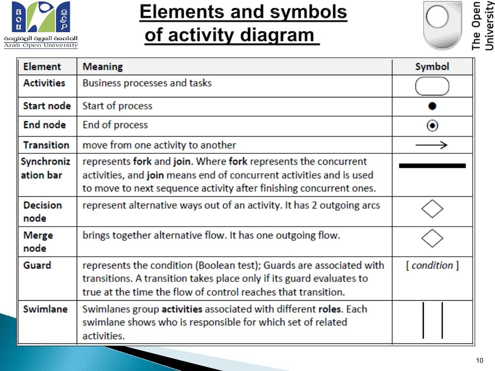
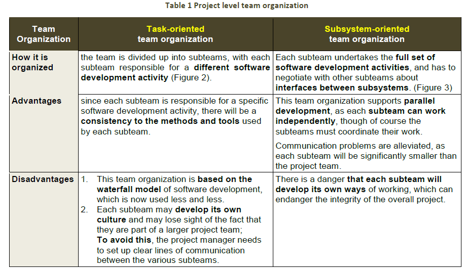
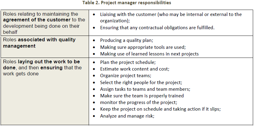
0 comments
Want to create your own Mind Maps for free with GoConqr? Learn more.