23577576
Description
Mind Map by RAJNIKANT KUSHWAHA,ECE18 Vel Tech, Chennai, updated more than 1 year ago
More
Capacitors
- Structure of Capacitor: A capacitor is
a device which stores electrical
charge. It is made of two metal
plates separated by an insulator
know as a dielectric. The dielectric is
usually made of oil, paper or air.
- Charging a capacitor: As the plates of the
capacitor are separated by an insulator,
the charge cannot fllow across the plates
when connected to a potential difference.
- Electrons flow from
the +Q plate of the
capacitor to the
positive end of the
battery.
- Electrons flow from
the negative side of
the battery to the -Q
plate of the capacitor.
- Electrons flow from
the negative side of
the battery to the -Q
plate of the capacitor.
- Current flows for a short time and
stops when the potential difference
across the capacitor is the same as
the p.d across the battery
- Electrons flow from
the +Q plate of the
capacitor to the
positive end of the
battery.
- Charging a capacitor: As the plates of the
capacitor are separated by an insulator,
the charge cannot fllow across the plates
when connected to a potential difference.
- Capacitance
definition: The
charge stored per
volt.
- C = Q / V
- C in Farads, F
Q in
Coulombs, C
V in Volts, V
- Farad definition:
A Coulomb per
Volt
- Farad definition:
A Coulomb per
Volt
- Energy stored in a
capacitor can be derived
from this equation:
- E = 1/2
QV
- E = 1/2
QV
- C in Farads, F
Q in
Coulombs, C
V in Volts, V
- C = Q / V
- In Series
- 1 / C = 1 / C1 + 1 / C2 + 1 / C3
- Charge is the
same everywhere
Voltage spilts
- Smallest Capacitor =
Largest P.D
- Smallest Capacitor =
Largest P.D
- Charge is the
same everywhere
Voltage spilts
- 1 / C = 1 / C1 + 1 / C2 + 1 / C3
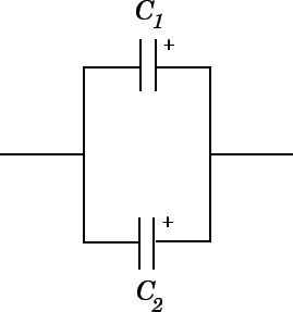
- In Parallel
- C = C1 + C2 +
C3
- Voltage is the same
everywhere Charge splits
- Largest
capacitor =
Largest charge
- If capacitors look like image on
right: They are joined in parallel;
there is no change to the total
charge stored; the p.d. across
the capacitors becomes equal;
the combined capacitance in
parallel is C1 + C2
- Largest
capacitor =
Largest charge
- Voltage is the same
everywhere Charge splits
- C = C1 + C2 +
C3
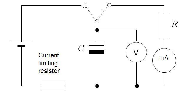
- 1) Set up apparatus as shown. Initially charge the
capacitor by flicking the switch to position 1, connecting
the capacitor to the power supply. 2) Discharge the
capacitor by flicking the switch to position 2. Record
current values at 10s intervals for 100s using stopwatch.
3) Plot graph of current against time.
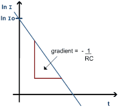
- I = Io e^ -t/RC
Q = Qo e^ -t/RC
V = Vo e^ -t/RC
- τ = RC
- Time constant is the time
taken for the current /
charge / voltage to fall to
0.368 of its initial value.
- The larger the value of RC,
the longer a capacitor will
take to discharge.
- Resolving the exponential
curve to a straight line
graph, results in the graph
to the right.
- Why the exponential shape?
Intially, the -ve side of the battery
is more -ve than -Q plate of the
capacitor so e- flow from the
battery to the -Q plate. Likewise
the Q+ plate is more -ve than the
=ve side of the battery so e- flow
from Q+ to +ve of battery. This
means at initally the capacitor is at
0V (uncharged) and the battery is
at 6V. Because of the large p.d,
there is a large flow of current.
Over time, the capacitor becomes
charged so the p.d between the
battery and the capacitor is
decreased. This means that the
flow of current will also decrease.
Eventually, the p.d across the
capacitor is equal to the p.d across
the battery. At this point, current
stops flowing.
- The larger the value of RC,
the longer a capacitor will
take to discharge.
- When t = RC; I = 0.368 Io
- Half life is the time taken for
current/ charge/ voltage to fall
to half its original value.
- If at t½, I = ½Io,
t = 0.693 RC
- If at t½, I = ½Io,
t = 0.693 RC
- Time constant is the time
taken for the current /
charge / voltage to fall to
0.368 of its initial value.
- I = Io e^ -t/RC
Q = Qo e^ -t/RC
V = Vo e^ -t/RC
- Applications
- Flash Gun
- Capacitor stores very little
charge. However when
discharged in a very short
space of time, the
electrical energy is
converted to light very
quickly, giving a flash gun
a large power output.
- Capacitor stores very little
charge. However when
discharged in a very short
space of time, the
electrical energy is
converted to light very
quickly, giving a flash gun
a large power output.
- Defibrillator
- Capacitor stores a large amount
of energy in the form of electrical
charge. It is then released over a
short period of time. For a
successful defibrillation, the
current delivered must be
maintained for several
milliseconds. However, the
current and charge delivered by a
discharging capacitor decay
rapidly. Therefore inductors are
used to prolong the duration of
current flow.
- Flash Gun
Media attachments
Want to create your own Mind Maps for free with GoConqr? Learn more.