
Flashcards
01Handout1
Flashcards do conjunto (24)
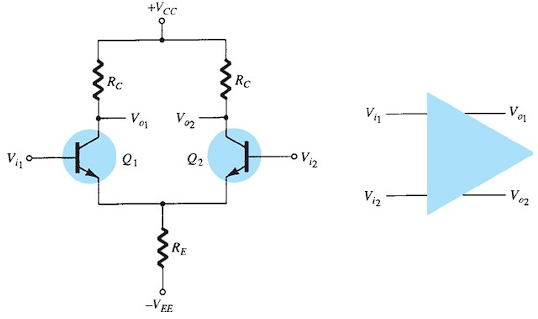
- 1Differential amplifierIts main feature is the very large gain when opposite signals are applied to the inputs.
- 2single-ended operationa single input signal applies and operates both transistors, resulting in output from both collectors.
- 3double-ended operationtwo input signals are applied, resulting in the difference of the signals applied to both inputs.
- 4common-mode operationthe common input signal results in opposite signals at each collector, these signals canceling, so
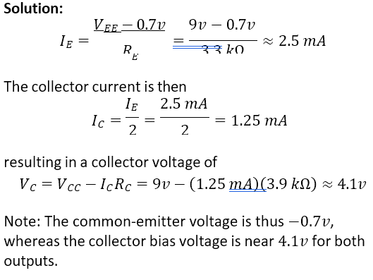
that the resulting output signal is zero. - 5DC BiasingConsider the DC bias operation of the circuit with ac inputs obtained from voltage sources, the dc voltage at each input is essentially connected to 0𝑣.
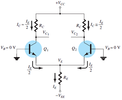
- 6common- emitter dc bias voltage formula𝑉𝐸 = 0𝑣 − 𝑉𝐵𝐸 = −0.7𝑣
- 7emitter dc bias current formula

- 8collector current formula
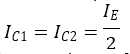
- 9collector voltage formula

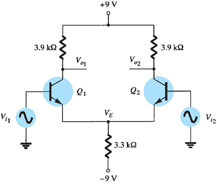
- 10Calculate the DC voltages and currents in the circuit. Find 𝐼𝐸 , 𝐼𝐶 , and 𝑉𝐶 .
- 11Operational AmplifiersIt is a very high gain differential amplifier with high input impedance and low output impedance.
It is a low-cost integrating circuit consisting of transistors, resistors, and capacitors.
Typical uses of these are to provide voltage amplitude changes (amplitude and polarity), oscillators, filter circuits, and many types of instrumentation circuits.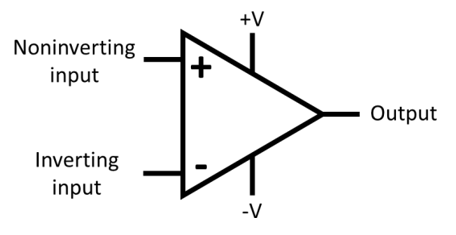
- 12•Thepositive power supply terminal. The negative power supply terminal. The inverting input is labeled−on the schematic symbol. The non-inverting input is labeled + on the schematic symbol. The fifth terminal, of course, is the output.Op-Amp Terminals
- 13Infinite open-loop gain. Infinite Input impedance. Zero Output Impedance.Op-Amp Properties
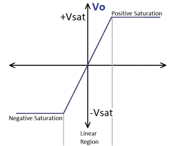
- 14•The graph that relates the output voltage to the input voltage is called the voltage transfer curve and is fundamental in designing and understanding amplifier circuits. Note the two distinct regions of operation: one around 𝑉𝑖 = 0𝑣, the linear region where the output changes linearly with respect to input, and the other at which changes in 𝑉𝑖 has little effect on 𝑉𝑂 , the saturation region (non-linear behavior). Circuits with operational amplifiers can be designed to operate in both regions. In the linear region, the slope of the line relating 𝑉𝑂 to 𝑉𝑖 is very large; indeed, it is equal to the open-loop gain 𝐴.Voltage Transfer Characteristics
- 15Negative Feedback Infinite Gain and Zero Input Current. Output Saturation Zero output voltage if the input voltage is zero.Ideal Op-Amp Characteristics
- 16Negative Feedbackis when you connect the output of a circuit back to its input so that the output “feeds back” into the circuit. When an increase in the output is fed back, it causes a decrease in the output. Negative feedback is like self-correction.
- 17Infinite Gain and Zero Input Current.When an op-amp is used in negative feedback, the consequence of infinite gain is that the two inputs will be forced to be equal. That is, the op-amp will output whatever voltage is necessary to make the two inputs equal.
- 18Output SaturationNaturally, an op-amp can only output voltages contained within the range of its power supply.
When the output voltage implied by the circuit would exceed the possible range, the op-amp is said to saturate, and it just outputs its maximum or minimum possible voltage instead.
When op-amp output saturation causes the signal to be cut off close to the rails, we say that the signal is clipped. - 19Zero output voltage if the input voltage is zero.It must follow Ohm’s Law.
- 20Single-Ended Input Double-Ended (Differential) Input Double-Ended OutputBasic Input/Output Stages
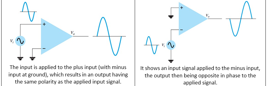
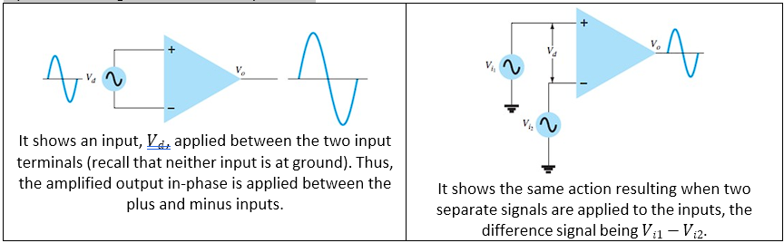
- 21Single-Ended InputThis operation results when the input signal is connected to one input with the other input connected to the ground.
- 22Double-Ended (Differential) InputIn addition to using only one input, it is possible to apply signals at each input—this being a double-ended operation.
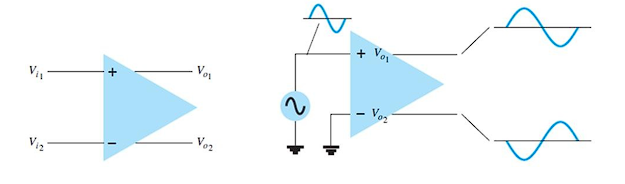
- 23Double-Ended Output -An input applied to either input will result in outputs from both output terminals; these outputs always being opposite in polarity.
- 24Op-Amp Common-Mode OperationWhen the same input signals are applied to both inputs, common-mode operation is performed.
Ideally, the two inputs are equally amplified, and since they result in opposite-polarity signals at the output, these signals cancel, resulting in 0𝑣 output.
Since there are noise (any unwanted input signal) common to both inputs, the differential connection tends to provide attenuation of this unwanted input, while providing an amplified output of the difference signal.
This operating feature is called common-mode rejection.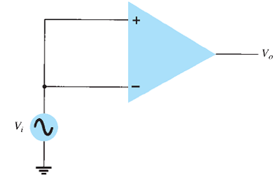
Informações
- Descrição
- hard Fundamentals of Mixed Signals and Sensors FlashCards sobre 01Handout1, criado por Eljin Aguilar em 13-08-2024.
- Criado por
- Eljin Aguilar · ago 2024
- Atualizado
- 17 set 2024
- Visualizações
- 2
- Avaliação