
Mapa mental
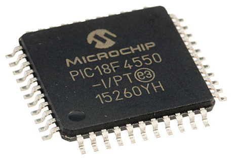
PIC18F4550
Conteúdo do mapa
PIC18F4550
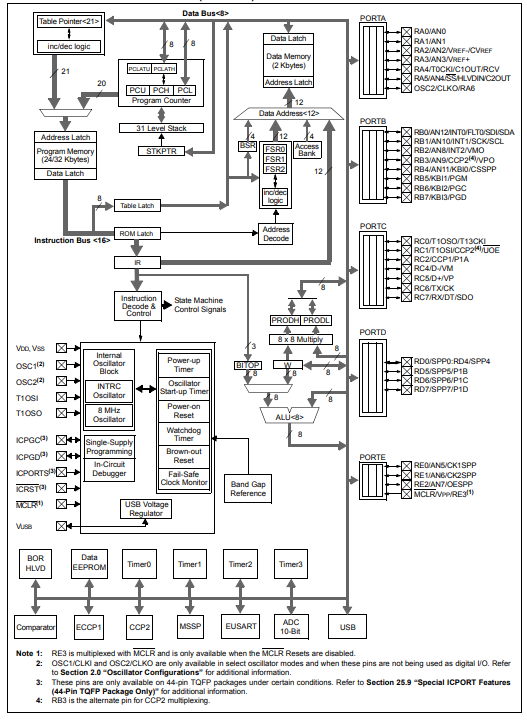
Block Diagram
¿What is it about?
- It is an integrated circuit (IC) that contains the entire structure of a microcomputer.
- CPU
- It Controls and executes the programm instructions
- Memory
- Ther are two types
- ROM Memory
- The program is stored in this memory
- RAM o SRAM
- Data are stored in this memory
- ROM Memory
- Ther are two types
- Ports(Peripherals)
- They are used to connect external elements to the microcontroller.
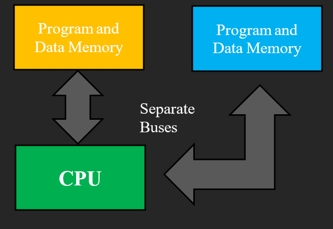
- What kind of topology does it have?
- Harvard Topology
- CPU
- It is an integrated circuit (IC) that contains the entire structure of a microcomputer.
What kind of peripherals does it have?
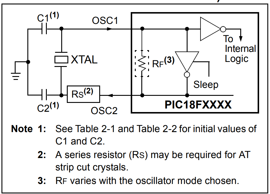
- Oscillator
- This signal is used to synchronize all system operations.
- How can I configure a oscillator on the microcontroller?
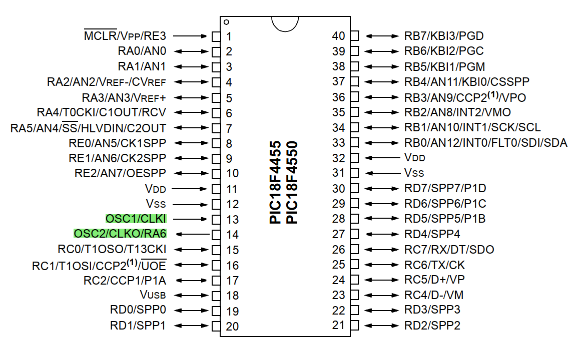
- Step1. The quartz crystals must be connected to the CLKI and CLKO pins, which can be found on the data sheet of each component.
- Step2. Configuration registers, CONFIG1L and CONFIG1H, select the oscillator mode and USB prescaler/postscaler options.
- Step3. The OSCCON register selects the Active Clock mode; it is primarily used in controlling clock switching in power-managed modes.
- Step4. The OSCTUNE register (Register 2-1) is used to trim the INTRC frequency source, as well as select the low-frequency clock source that drives several special features.
- Timers
- It is an internal counter that determines a precise time between the moment the value is loaded and the moment it overflows.
- Programm Memory
- Memory section where the instructions governing the application are stored. This memory is of the non-volatile type.
- Data Memory
- Memory responsible for storing variables and data. This memory is volatile.
- Interruptions
- Mechanism by which an internal or external event can interrupt the execution of a program at any time. From that moment a jump to a subroutine of attention to the interruption occurs, this one immediately attends the event and resumes exactly where it was at the moment of being interrupted, continuing its task just where it left off.
- Module Capture
- This mode captures the arrival time of a signal, i.e. it captures the value of Timer1 when the CCP pin goes high.
- Comparator Module
- It acts as an analog comparator that generates an output when the value of timer1 reaches a certain reference value.
- PWM Module
- It provides a pulse width modulated output.
- Oscillator
How can I configure a port on the microcontroller?
- The microcontroller PIC18F4550 has 5 ports.
- PORTA has 7 lines: RA0-RA6
- PORTB has 8 lines: RB0-RB7
- PORTC has 7 lines: RC0-RC2 and RC4-RC7
- PORTD has 8 lines: RD0-RD7
- PORTE has 4 lines: RE0-RE3
- Each line can be configured as an input or output independently of each other. When the line is configured with a value equal to "0", it is taken as an Output. If the line is configured with a value equal to "1", it is taken as an input.
- The microcontroller PIC18F4550 has 5 ports.
Imagens e arquivos do mapa

Informações
- Descrição
- Mapa Mental sobre PIC18F4550, criado por Ivan Mora em 05-09-2023.
- Criado por
- Ivan Mora
- Visualizações
- 3
- Avaliação