
Mapa mental
Filter Circuits
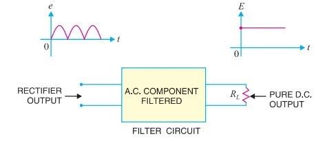
Conteúdo do mapa
Filter Circuits
Definition
- A filter circuit is a device which removes the a.c. component of rectifier output but allows the d.c. component to reach the load.
- Is a combination of inductors (L) and capacitors (C).
- A filter circuit is a device which removes the a.c. component of rectifier output but allows the d.c. component to reach the load.
Types of Filter Circuits
- Capacitor filter.
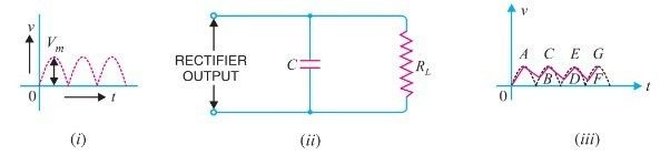
- The pulsating direct voltage of the rectifier is applied across the capacitor.
- As the rectifier voltage increases, it charges the capacitor and also supplies current to the load.
- At the end of quarter cycle capacitor is charged to the peak value Vm of the rectifier voltage.
- Now, the rectifier voltage starts to decrease.
- As this occurs, the capacitor discharges through the load and voltage across it
- As this occurs, the capacitor discharges through the load and voltage across it
- Now, the rectifier voltage starts to decrease.
- At the end of quarter cycle capacitor is charged to the peak value Vm of the rectifier voltage.
- As the rectifier voltage increases, it charges the capacitor and also supplies current to the load.
- low cost, small size, little weight and good characteristics.
- The pulsating direct voltage of the rectifier is applied across the capacitor.
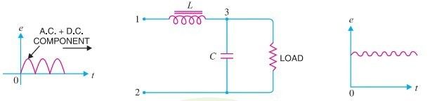
- Choke input filter.
- As the rectifier voltage increases, it charges the capacitor and also supplies current to the load. At the end of quarter cycle capacitor is charged to the peak value Vm of the rectifier voltage. Now, the rectifier voltage starts to decrease. As this occurs, the capacitor discharges through the load and voltage across it decreases as shown by the line AB.
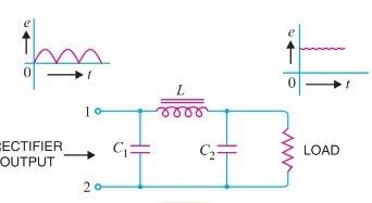
- Capacitor input filter or π-filter.
- Several identical sections are often used to reduce the pulsations as effectively as possible.
- The pulsating output from the rectifier is applied across the input terminals (i.e. terminals 1 and 2) of the filter.
- Several identical sections are often used to reduce the pulsations as effectively as possible.
- Capacitor filter.
Imagens e arquivos do mapa
Informações
- Descrição
- Mapa Mental sobre Filter Circuits, criado por pablo a em 01-03-2019.
- Criado por
- pablo a
- Visualizações
- 0
- Avaliação