
Quiz
Electrical Engineering Pre-Interview Quiz
Este quiz tem tempo limite, por isso abre no player de sempre.
Perguntas do quiz (99)
1Symbol on a picture is for:
- ACapacitor
- BInductor
- CResistor
2What are typical values for resistors that one can buy?
- ApOhm - nOhm
- BnOhm - mOhm
- CmOhm - MOhm
- DMOhm - TOhm
3Symbol on a picture is for:
- ACapacitor
- BInductor
- CResistor
4What are typical values for capacitors that one can buy?
- ApF - mF
- BmF - kF
- CkF - MF
5Symbol on a picture is for:
- ACapacitor
- BInductor
- CResistor
6What are typical values for coils and/or inductors that one can buy?
- ApH - nH
- BnH - mH
- CmH - MH
- DMH - TH
7What is ideal ammeter resistance and how one should connect it in circuit?
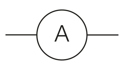
- AZero resistance, parallel
- BZero resistance, in series
- CInfinite resistance, parallel
- DInfinite resistance, in series
8What is ideal voltmeter resistance and how one should connect it in circuit?
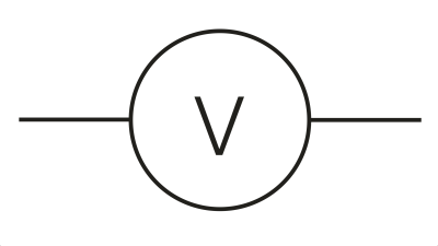
- AZero resistance, parallel
- BZero resistance, in series
- CInfinite resistance, parallel
- DInfinite resistance, in series
9Symbol on a picture is for:
- APNP transistor
- BNPN transistor
- CN-Channel MOSFET
- DP-Channel MOSFET
10Symbol on a picture is for:
- APNP transistor
- BNPN transistor
- CN-Channel MOSFET
- DP-Channel MOSFET
11Symbol on a picture is for:
- APNP transistor
- BNPN transistor
- CN-Channel MOSFET
- DP-Channel MOSFET
12Symbol on a picture is for:
- APNP transistor
- BNPN transistor
- CN-Channel MOSFET
- DP-Channel MOSFET
13What is equivalent resistance of that circuit?
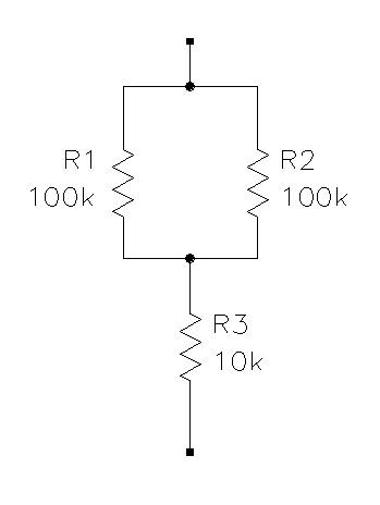
- A~9.52 kOhm
- B10 kOhm
- C50 kOhm
- D60 kOhm
- E100 kOhm
14What is equivalent inductance of that circuit?
- AmH
- BnH
15What is equivalent capacitance of that circuit?
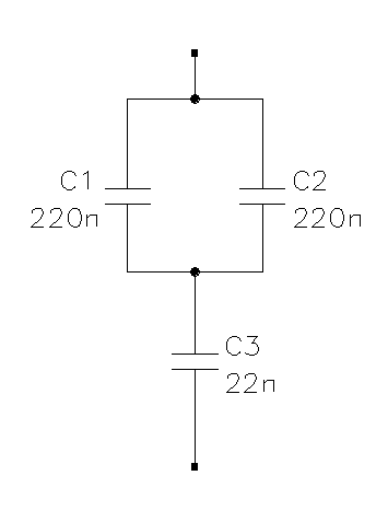
- A~20.95 nF
- B22 nF
- C132 nF
- D220 nF
- E242 nF
16NTC is a type of:
- ACapacitor with negative temperature coefficient
- BInductor with negative temperature coefficient
- CResistor with negative temperature coefficient
- DTransistor with negative temperature coefficient
17PTC is a type of:
- ACapacitor with positive temperature coefficient
- BInductor with positive temperature coefficient
- CResistor with positive temperature coefficient
- DTransistor with positive temperature coefficient
18What is E24, E96, E192?
- ACodes of capacitors from different classes
- BPackage codes of inductors
- CStandard resistor series
- DTransistor current gain codes
19What is C0G, X7R, Y5V?
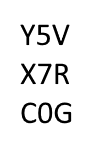
- ACodes of capacitors from different classes
- BPackage codes of inductors
- CStandard resistor series
- DTransistor current gain codes
20Assign capacitor types to given chart:
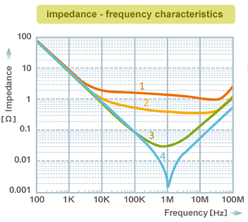
- A1 (red) - Ceramic,
2 (orange) - Electrolytic,
3 (green) - Polymer,
4 (blue) - Tantalum. - B1 (red) - Tantalum,
2 (orange) - Polymer,
3 (green) - Electrolytic,
4 (blue) - Ceramic. - C1 (red) - Ceramic,
2 (orange) - Polymer,
3 (green) - Tantalum,
4 (blue) - Electrolytic. - D1 (red) - Electrolytic,
2 (orange) - Tantalum,
3 (green) - Polymer,
4 (blue) - Ceramic.
- A1 (red) - Ceramic,
21What is voltage gain of circuit shown (equal resistances)?
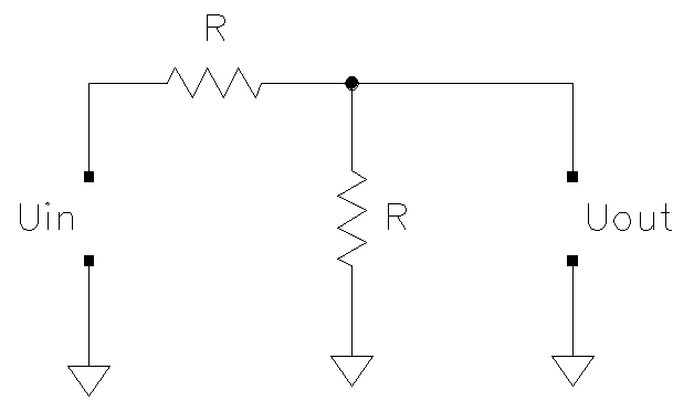
- A0.5 that is - 3 dB
- B0.5 that is - 6 dB
- C1.0 that is 3 dB
- D1.0 that is 6 dB
- E2.0 that is 3 dB
- F2.0 that is 6 dB
22What will be the voltage value at output after 10 ms for first order RC filter (R = 10 kOhm, C = 100 nF, at t = 0 Uin changes from 0 V to 12 V)?
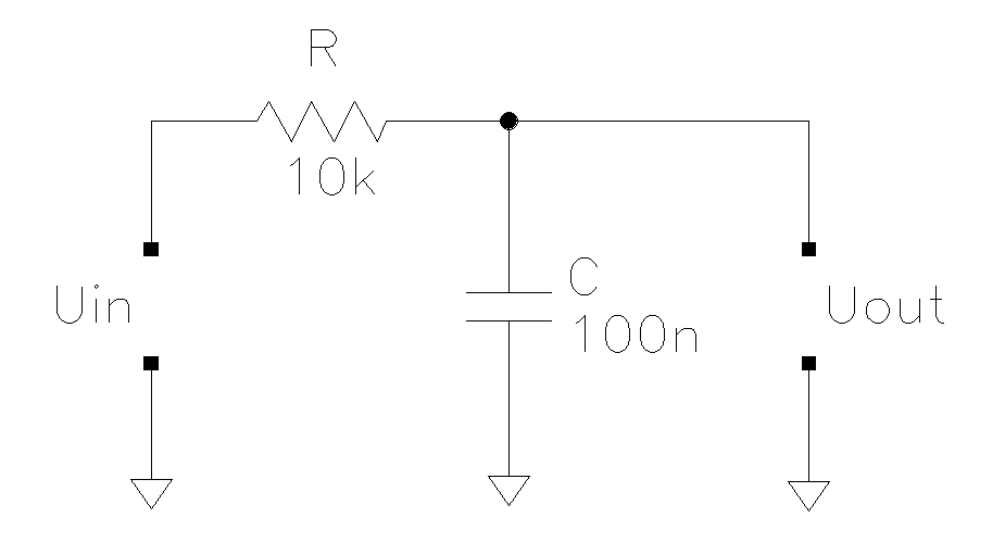
- A0 V
- B~6 V
- C~12 V
- DInfinite
- EUnknown
23Is it possible to check with multimeter if bipolar transistor is working or damaged?
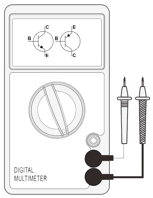
- AYes
- BNo
- CMaybe
24When thinking of PCB design, the bigger current:
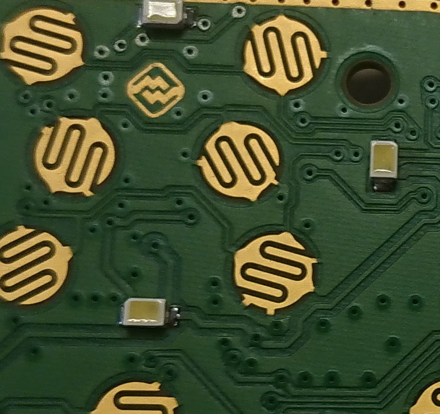
- Athinner trace
- Bbigger clearance
- Cwider trace
25When thinking of PCB design, the higher voltage:
- Athe smaller clearance
- Bthe wider traces
- Cthe bigger clearance
26What you see on picture are probably:
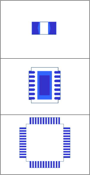
- ASOT23, SOIC, QFP
- BChip Resistor, Chip Transistor, QFP
- CChip Resistor, SON IC, QFP
27What is typical (commercial) electronic temperature range?
- A0°C to 70°C, sometimes specified to 85°C
- B-40°C to 85°C, sometimes specified to 150°C
- C-55°C to 125°C
28What is automotive (Grade 3) temperature range?
- A0°C to 85°C
- B0°C to 150°C
- C-40°C to 85°C
- D-80°C to 225°C
29What you associate EMC with:
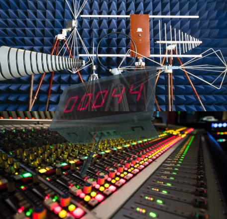
- AElectromagnetic Music Counter
- BElectromagnetic Compatibility
- CElectro Media Console
30What is general rule for placing capacitors on power supply lines on circuit board?
- APlace all capacitors (regardless capacitance) together in one place on board
- BPlace capacitors as close as possible to supply pin of the IC’s that cap is dedicated
- CPlace all capacitors close to the main connector
- DIt does not matter where to place them as long as electrical connection is present
31Single Ended trace impedance depends on:
- ATrace width
- BCopper thickness
- CDielectric relative permittivity
- DDielectric thickness (distance to next solid reference plane layer)
- EReference plane (distance, shape, breaks, etc.)
- FAll of the above
32Copper thickness on printed board affects:
- ATrace conductivity
- BMaximum allowable current (current capacity)
- CThermal behavior
- DCosts
- ETrack/trace spacing
- FAll of the above
33What we see on picture is cross section of:
- ANTC
- BPCB
- CRTD
34What are tracks/traces and what is their purpose:
- APrinted or etched wire on a printed circuit board, electrically connects electronic components
- BAre made of dielectric to protect components
- CPrinted with special non-conductive ink notes on board that describes how components should be placed on board
35Tombstone effect is:
- ADeath of soldering station operator due to flux fumes
- BMounting condition whereby a leadless device has only one of its metallized terminations soldered
- CFailure of component during ESD test
36Component on picture marked with red circle is probably:
- ALED
- BResistor
- CCeramic capacitor
- DElectrolytic capacitor
- EIC
37Component on picture marked with red circle is probably:
- ALED
- BResistor
- CCeramic capacitor
- DElectrolytic capacitor
- EIC
38Component on picture marked with red circle is probably:
- ALED
- BResistor
- CCeramic capacitor
- DElectrolytic capacitor
- EIC
39Component on picture marked with red circle is probably:
- ALED
- BResistor
- CCeramic capacitor
- DElectrolytic capacitor
- EIC
40Component on picture marked with red circle is probably:
- ALED
- BResistor
- CCeramic capacitor
- DElectrolytic capacitor
- EIC
410x1F equals in decimal:
- A16
- B25
- C31
- D271
42What is the reason to place fiducials on PCB?
- AFiducials are kind of test coupons used to check if PCB meets manufacturing requirements
- BFiducials acts as reference points for stencil and automated component placement
- CFiducials are used to check solder mask breakdown voltage
- DThere is no need to place fiducials on PCB
43Calculate resistor value knowing that desired luminous flux can be achieved by I = 10 mA and that current causes U = 2 V voltage drop on LED.
- A1 Ω
- B1.2 Ω
- C1 kΩ
- D1.2 kΩ
- E12 kΩ
- F1000 kΩ
44What is SMT?
- ATechnology in which the electrical components are mounted into drilled holes in a PCB.
- BMethod in which the electrical components are mounted directly onto the surface of a PCB.
- CSpecial marks technology that is used for automated electrical PCB check.
45What is ESD?
- ASudden flow of electricity between two electrically charged objects
- BType of ceramic chip antenna
- COne of destructive electronic system tests that electronics are subjected to
46What is DRC?
- AOne of capacitor electrical parameter
- BLeakage current caused by drain resistance
- CType of automated PCB design verification
47Select better routing technique for bend geometry
- AA
- BB
48Select best method of connecting traces to pads:
- AA
- BB
- CC
- DD
49Choose best solution of connecting power supply to IC (VCC+GND)
- AA
- BB
- CC
- DD
50Which of periodic waveforms has wider frequency spectrum?
- AA
- BB
51What is thermocouple?
- ACouple of electrical elements used to heat up electronic module in low temperatures
- BElectrical device that produces temperature dependent voltage
- CElectrical device that analyzes composition of vapor
52What value meter will show (ammeter)
- A1
- B2
- C3
53What value meter will show (voltmeter)
- A1
- B2
- C3
54What is dB?
- ADummy board used during prototyping
- BUnit of measurement used to express the ratio of one value to another on a linear scale
- CRelative unit of measurement used to express the ratio of one value to another on a logarithmic scale
55Symbol on a picture is for:
- ATwo input NAND gate
- BTwo input NOR gate
- CTwo input NOT gate
56Symbol on a picture is for:
- ATwo input NAND gate
- BTwo input NOR gate
- CTwo input NOT gate
57What is typical inductance for single via?
- AUsually below 2nH
- BUsually between 12 and 100 nH
- CUsually above 120 nH
58What is PCB via?
- AAn electrical connection between layers
- BA trace connecting connecting two connectors
- CA type of tooling hole used during automatic component placement
59What is cross talk?
- AFull duplex communication interface between microcontrollers
- BOfficial communication way agreed between supplier and electronic designer
- CUnwanted transfer of energy from one transmission line to another
60What kind of circuit is presented on picture?
- ALow pass filter
- BHigh pass filer
- CBand pass filter
- DBand stop filter
61What kind of circuit is presented on picture?
- ALow pass filter
- BHigh pass filer
- CBand pass filter
- DBand stop filter
62What kind of circuit is presented on picture?
- ALow pass filter
- BHigh pass filer
- CBand pass filter
- DBand stop filter
63What kind of circuit is presented on picture?
- ALow pass filter
- BHigh pass filer
- CBand pass filter
- DBand stop filter
64What kind of circuit is presented on picture?
- AInverting amplifier
- BNon-Inverting amplifier
- CDifferential amplifier
65What kind of circuit is presented on picture?
- AInverting amplifier
- BNon-Inverting amplifier
- CDifferential amplifier
66What kind of circuit is presented on picture?
- AInverting amplifier
- BNon-Inverting amplifier
- CDifferential amplifier
67What kind of circuit is presented on picture?
- ACurrent source
- BVoltage regulator
- CBuck converter
- DBoost converter
68What kind of circuit is presented on picture?
- ACurrent source
- BVoltage regulator
- CBuck converter
- DBoost converter
69What kind of circuit is presented on picture?
- ACurrent source
- BVoltage regulator
- CBuck converter
- DBoost converter
70What kind of circuit is presented on picture?
- ACurrent source
- BVoltage regulator
- CBuck converter
- DBoost converter
71RTD can be used to measure temperature.
- AVerdadeiro
- BFalso
72Thermocouple can be used to measure temperature.
- AVerdadeiro
- BFalso
73Diode can be used to measure temperature.
- AVerdadeiro
- BFalso
74Thermistor can be used to measure temperature.
- AVerdadeiro
- BFalso
75Transistor can be used to measure temperature.
- AVerdadeiro
- BFalso
76Linear voltage regulator in comparison with switching mode power supply is more noisy.
- AVerdadeiro
- BFalso
77Linear voltage regulator in comparison with switching mode power supply is more efficient.
- AVerdadeiro
- BFalso
78Linear voltage regulator in comparison with switching mode power supply requires more components (inductors, capacitors, etc.).
- AVerdadeiro
- BFalso
79Symbol on a picture is for:
- ALED
- BTVS
- CZener diode
80Symbol on a picture is for:
- ALED
- BTVS
- CZener diode
81Symbol on a picture is for:
- ALED
- BTVS
- CZener diode
82Symbol on a picture is for:
- AOperational amplifier
- BAdder
- CAND gate
83Symbol on a picture is for:
- AResistor
- BFuse
- CVaristor
84Symbol on a picture is for:
- ACrystal oscillator
- BElectrolytic capacitor
- CFuse
85Testing the NPN transistor
Using ohmmeter, connecting positive terminal to base and negative to emitter, the reading will be:- AShort circuit (0Ω)
- BLow resistance
- COpen circuit
86Testing the NPN transistor
Using ohmmeter, connecting negative terminal to base and positive to emitter, the reading will be:- AShort circuit (0Ω)
- BLow resistance
- COpen circuit
87Testing the NPN transistor
Using ohmmeter, connecting positive terminal to collector and negative to base, the reading will be:- AShort circuit (0Ω)
- BLow resistance
- COpen circuit
88Testing the NPN transistor
Using ohmmeter, connecting negative terminal to collector and positive to base, the reading will be:- AShort circuit (0Ω)
- BLow resistance
- COpen circuit
89Testing the NPN transistor
Using ohmmeter, connecting positive terminal to collector and negative to emitter, the reading will be:- AShort circuit (0Ω)
- BLow resistance
- COpen circuit
90Testing the NPN transistor
Using ohmmeter, connecting negative terminal to collector and positive to emitter, the reading will be:- AShort circuit (0Ω)
- BLow resistance
- COpen circuit
91Testing the PNP transistor
Using ohmmeter, connecting positive terminal to base and negative to emitter, the reading will be:- AShort circuit (0Ω)
- BLow resistance
- COpen circuit
92Testing the PNP transistor
Using ohmmeter, connecting negative terminal to base and positive to emitter, the reading will be:- AShort circuit (0Ω)
- BLow resistance
- COpen circuit
93Testing the PNP transistor
Using ohmmeter, connecting positive terminal to collector and negative to base, the reading will be:- AShort circuit (0Ω)
- BLow resistance
- COpen circuit
94Testing the PNP transistor
Using ohmmeter, connecting negative terminal to collector and positive to base, the reading will be:- AShort circuit (0Ω)
- BLow resistance
- COpen circuit
95Testing the PNP transistor
Using ohmmeter, connecting positive terminal to collector and negative to emitter, the reading will be:- AShort circuit (0Ω)
- BLow resistance
- COpen circuit
96Testing the PNP transistor
Using ohmmeter, connecting negative terminal to collector and positive to emitter, the reading will be:- AShort circuit (0Ω)
- BLow resistance
- COpen circuit
97UART is a:
- ADifferential communication interface
- BCommunication standard where logic 1 is voltage +12 V and logic 0 is -12 V
- CAsynchronous serial communication
98SPI in comparison with I2C:
- ARequires only two (2) lines vs. minimum four (4) for I2C
- BCan be much faster than I2C
- CIs half-duplex vs. full duplex for I2C
99LIN in comparison with CAN is:
- AMuch faster
- BSingle wire vs. twisted pair required in CAN
- CMuch complex
Informações
- Descrição
- Electrical Engineering Quiz sobre Electrical Engineering Pre-Interview Quiz, criado por Piotr Orlik em 02-10-2020.
- Autor
- Piotr Orlik
- Idioma
- English
- Visualizações
- 19
- Histórico
- Criado em 2 out 2020 · atualizado em 20 out 2020
- Etiquetas
- Avaliação
- Ainda sem avaliações Avalie este quiz