4252367
Computed Radiography & Digital Radiography
Description
No tags specified
Slide Set by Rutendo Chingomb, updated more than 1 year ago
More
Less
|
|
Created by Rutendo Chingomb
over 8 years ago
|
|
Resource summary
Slide 1
CR and DR
Image
Receptor:–Film
screen–Computed
Radiography
–Direct
Digital Radiography (DDR/DR)The
computer processing means that systems have a far greater latitude compared to
film/screen. But
knowing what happens when you set/manipulate exposure factors still mattersIncreasing kVp also
increases beam quantity to a
certain extent: because the electrons with more energy are more efficient at
removing K-shell electrons. Intensity
∝ kVp2CR has a tube potential (kVp) that determines the subject contrast in the resultant image - this is connected to K- edge of the receptors
Anatomical tissues vary in absorption and
transmission create a range of dark and light areas
Remember it is the degree of
photoelectric absorption that determines the range of greys visible on the
radiographic image. This degree of absorption is strongly dependent on both the
density and inversely proportional to beam energy
This is what creates the radiographic
image. Since it is the interaction of the outer electrons that usually
influence the degree of absorption, transmission, or scatter, the radiographic
can be thought of as a map of electron density
And whilst CR and DR has a wide exposure latitude if there isn't enough information to make a diagnostic image then there isn't enough!
Slide 2
Formally
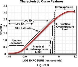
it is the tonal range generated within an exposure.
Sometimes
called a characteristic curve, that has axes of transmitted light (ie
range of greys very light to very dark), and exposure (logarithmic
Sometimes
called the dynamic range
In
digital imaging, changing kVp affects the amount of
radiation reaching the image receptor and
affects subject
contrast (differential attenuation or inherent contrast)
In
digital imaging, brightness and image contrast are primary
controlled during computer processing – but you still need to be aware of the
effect of kVp on
subject (inherent) contrast
Exposure Latitude
Caption: : Speed of ‘film’ is related to the gradient – a faster film has a steeper gradient, historically because the crystals which made up the film were bigger, requiring less exposure to oxidise to silver. A slower film therefore had smaller crystals requiring more exposure per unit time to generate the same degree of oxidation
Slide 3
Film screen vs CR
CR
and DR are digital imaging modalities. Both CR and DR are relative newcomers to
x-ray imaging
Film-screen
uses a cassette similar to the cassette used in CR
Film-screen
uses a processor with chemicals where as CR uses a digital processor
In
CR the film and intensifying screen is replaced with a phosphor plate
CR equipment:Cassette
and phosphor plate, Laser
Image Reader, PACSCR Advantages
–A
digital image is generated–Ability
to retrofit to existing radiography equipment –Mobile
radiography is easily accomplished –Excellent
image quality –Initially
less expensive than DR CR disadvantages –Still
have to use an imaging plate–No
real time saving benefit over traditional radiography–Need
to purchase an imaging reader
Imaging Plate
Average
life cycle over 10000 uses
Two
year warranty
Average
cost £ 1000 each
Flexible
Durable
High
Absorption efficiency - high
% of incoming x-rays effectively contribute to information capture, therefore
enabling x-ray dose reduction
Smooth
Shiny surface
Correct
& Incorrect sides? TUBE side
35 x 43 cm, 35 x 35 cm, 24 x 30 cm, 18 x 24 cm, 15 x 30 cm Storage: Upright ( NOT flat) to prevent pressure on the Phosphor plate. Must not be left unprotected in the x-ray room, sensitive to scatter. Cleaning: Every TWO weeks and erased. If not there is an increased risk of becoming stuck in the digitizer. Cassette Erasure –Erased ONCE a week at least, UHL it is done first thing every day. Reduce risk of ghost image.
Slide 4
Phosphor Plate
Phosphor plate: Photo-stimulable storage phosphor plate, that stores the
latent image, is a re-usable detector.Two
part process:
1.converting incoming x-rays to light
photons - image capture
2.converting light into electrical signal - image readoutLaser Image Reader: Scanning mechanism to
extract the latent image from the plate.
Transmitted to network for
review/reporting etc
Through the PACS systemPhosphor
plate is analogous to film – it is sensitive to x-ray irradiation, whereas film
is not; BUT to demonstrate what happens during an x-ray exposure instead of an intensifying screen – a scintilator
which converts x-ray to visible light which exposes a film, the light is
trapped within the plate to be read out later
Slide 5
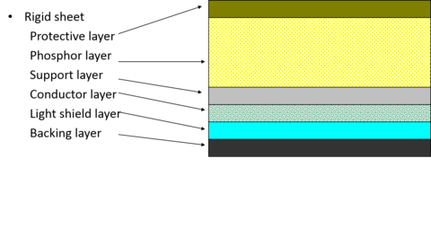
Protective layer - thin
& transparent, tough
and clear. Protects the phosphor layer during handling
from damage.Phosphor layer - active
component, barium fluorohalide
crystals doped with europium, contains
colour centres or F centres, which trap electrons during an exposure.Support
layer - semi
rigid, give
strength to the plateConductor
layer - absorbs
and removes static electricity Light
shield layer - reflective
layer, sends
light in forward direction when released in the reader, ensuring as much light
as possible is recordedBacking
layer - protects the back of the cassette.
Slide 6
Latent Image Acquisition
•Exit
photons are absorbed by the atoms of the phosphor and europium
•This
is by the photoelectric effect
Phosphor plate - image capture
The absorbed energy excites the electrons
They are raised to a higher energy state
Here they become stored/trapped in colour (F) centres
This is what forms the latent image
The number of electrons trapped in the F centres is directly related to X-ray beam intensity
This energy ( latent image ) can be stored for several hours
However the image will lose about 25%of its energy in 7-8 hours
The latent image is processed by loading the cassette into an image reader.
Image reader unit (digitiser)
The cassette is placed into the reader
unit
The imaging plate is extracted and
scanned
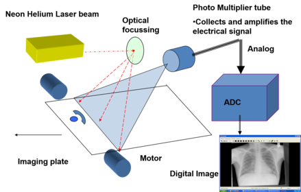
The image plate is scanned with a finely
focussed helium-neon laser
beam.
The laser releases the trapped electrons
and they return to a lower energy state.
This releases energy as visible light.
Slide 7
Digitiser
The
varying electrical signals are analogue, converted by an ADC to a digital image.
Once
the plate is read it is erased to remove all trace of the latent image
By
exposing the plate with intense white light to release any trapped electrons.
Imaging
plates are sensitive to `Scatter radiation` and should be erased once a week to
prevent background signal build up. The readers have an erase mode
The scanning of the plate results in a
continuous pattern of light intensities sent to a photomultiplier tube (which
is a photo detector)
Photomultiplier tube
collects, amplifies and coverts the light to an electrical signal
The electrical signal is proportional to
the range of energies stored in the image plate.
Slide 8
Matrix
A
digital image is made up of a 2D array of numbers called a MatrixBit depth - A
descriptor of the grey scale value attributed to each picture elementPixels are the smallest component of a matrixThe density of each Pixel ( picture
element) has to be a whole number. Each pixel has a bit depth or a number of
bits which controls the brightness of the pixel – 4bit, 8 bit, 10 bit or 12 bitThe greater the bit depth the more the
precise digitalization of the analogue signal, and the greater the various
shades of grey
This is turn improves its contrast
resolution - a previous slide suggested
that 1024 discrete shades of grey can be displayed - but we should consider actually how shades of
grey can the eye distinguish under optimum image display conditions?It
is now established that the human eye can discriminate 'between 700 and 900
simultaneous shades of gray for
the available luminance range of current medical displays and in optimal
conditions.' It is presently felt that it is of 'no use to simultaneously
display more than 10 bits of gray (1,024 gray shades) because this already exceeds the
capabilities of the human visual systemLarger the matrix size, greater the
number of pixels, better the image quality
Slide 9
What next
Now we have an image, what happens next?
PACS – Picture Archiving and
Communication System
Images are captured by a “ Image Server
”. PACS does not generate any images, simply handles the data.
The Server is the primary point of entry. It
receives digital signals from all radiology modalities, CT, MR, NM, C-arm, DSA,
digitisers…
The language of medical digital imaging is
called “DICOM”.
DICOM allows various components to communicate
with each other.
In PACS these images are captured as data
frames and routed through a server to digital display monitor.
For more information please see resources
on blackboard
Slide 10
CR imaging screens are ‘doped’ usually
Barium Fluorohalide;
with a small quantity of Europium.
The addition of Eu
causes defects within the crystal lattice which allows electrons to become
trapped more efficiently (F-Centre)
Incident x-ray is absorbed by the BaFH:Eu
phosphor – which oxidises the Eu atoms, the electrons liberated by this
process become trapped in a higher energy metastable
state
This is the ‘latent’
image
The number of trapped electrons is
proportional to the intensity of the incident x-ray beam
Flat panel: Caesium Iodide or Selenium
detector ( FPD)
Absorbs x-rays directly and converts into
a digital signal in 4 - 8 seconds
Indirect flat panel detectors use an intensifying screen or scintillator to convert x-rays to visible light, and then to a photodetector to produce a visible image
Direct flat panel detectors use incident
x-rays to generate free electrons which generate the ‘latent’ image directly.
Selenium is commonly used as a
photoconductor
A large voltage difference is applied
across the array at the same time, which causes the electrons to move to their
detectors.
CR vs DR
Slide 11
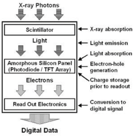
Indirect Digital Radiography
Caesium Iodide doped detectors are used as indirect flat panel detectors – there is a intermediate step in the generation of a digital signal.
Incident x-ray photons interact via photoelectric absorption
This leads to scintillation
The light is detected by a photodiode
The intensity of the light is directly
proportional to the number of incident x-ray photons
Slide 12
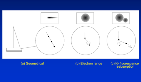
a)Internal
reflection and diffusion processes
b) the electron can wander about ionising
as it goes and losing energy, or
c)Can be absorbed by another atom leading
to another ionisation type event, with corresponding re-emission of light. This
would simulate x-ray incidence additional to the primary point
d)How can you tell which is which – You
cant, since the number of interactions is a phenomenal amount (259 * 6.023
x10exp23) ions present in 1 mole of CsI
e)Approx ten times the number of stars in the known
universe (1 x 10 exp 24)
Blurring and spatial resolution
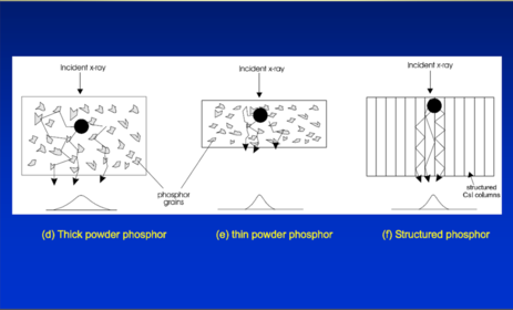
Caption: : d) Wide range of intensity e) Narrower range, but decreased amplitude –so less light available f) So structured phosphor is the way to go
Slide 13
Solutions
Have a thin phosphor plate (0.5 to 2 mm thick)
Have detectors parallel to the incident
x-ray
Each crystal needle is very fine between
5 and 20 µm in width
The edges of the crystals act as light
guides, the detector can either be on top of the crystals or below
Slide 14
Direct Digital Radiography
Selenium is a metalloid material,
exhibiting both insulator and conductor properties depending on it’s state – it
has several allotropes (cf
sulphur or carbon).
The
selenium-based technology uses an amorphous selenium-coated
thin-film-transistor (TFT) array to capture and convert X-ray energy directly
into digital signals.
Incident X-rays directly generate electron-hole
pairs in the selenium layer
via photoelectric absorption.
These charges are collected by individual
storage capacitors associated with each detector element for readout by
customised electronics within the array.
A Bias voltage is applied across the detector
structure during the exposure
When the exposure is terminated the
individual detector elements are read, which generates the x-ray image
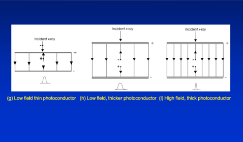
Caption: : g) Low Potential, electrons can ‘easily’ accumulate on adjacent capacitor plates h) Thicker photoconductor means more electron/hole pairs generated, but still low potential so see above i) High field constrains electrons to discrete capacitor plates, thick photoconductor ensures plenty on electron/hole pairs
Slide 15
Software
converts to appropriate grey scale pixels according to voltage (proportional
to intensity of incident x-ray photons)
Higher
spatial
resolution - mammography applications down to 50 microns
Direct
conversion of x-rays to an electrical charge
Can
have in excess of 7 million detectors on a 40cm x 40cm plate.
Images
are available within 3-8 seconds
DDR image receptor
DDR Advantages
No processing time and almost immediate
image acquisition
Excellent image quality
Pre readout info attributes appropriate
image algorithm
Immediate transfer to PACS / ER / Review
terminal
DDR Disadvantages
More expensive than CR
The imaging sensor is more expensive to
replace than an imaging plate or cassette (of the order of ~ £20,000 each c/w
~£1-2000 each for 35 x 43 CR plate)
Cannot usually
retrofit to existing x-ray equipment – but some companies offer stand alone
solutions
Slide 16
Dose
Slightly
reduced with DR – depending on whose literature you read, upto 50%
dose saving
Resolution
CR and DR are similar, DR is better for very
high resolution applications
Speed
/ throughput
DDR
is faster as there is no intermediate steps before next image acquisition
Can
use ‘tomosynthesis’ –
repeated acquisition in plane at different projection angle to enhance lesion
detection – lower dose than standard multi-planar projection
Cost
CR is
cheaper than DDR
CR vs DDR
Caption: : Amorphous selenium–based direct conversion DR systems. (a) Drawing illustrates a selenium drum–based system. A rotating selenium-dotted drum with a positive electrical surface charge is exposed to x-rays. Alteration of the charge pattern of the drum surface is proportional to the incident x-rays. The charge pattern is then converted into a digital image by an analog-to-digital (A/D) converter. (b) Drawing illustrates a selenium-based flat-panel detector system. Incident x-ray energy is directly converted into electrical charges within the fixed photo-conductor layer and read out by a linked TFT array beneath the detective layer.
Slide 17
These are variants to flat panel
detectors – used in cameras, video cameras, telescopes, and some mobile
phones*.
Electrons are liberated through the same
process as CR, but using visible light instead of x-ray photons.
The principle difference is that the
detector is itself an integrated circuit made of crystalline silicon.
The pixel electronics are etched onto the
surface of the chip.
The images produced in this way are of
high quality.
They are used in video fluoroscopy and
cine radiography applications, and for very small field radiography such as
dental applications.Quip about CMOS detectors and infra red
detector (remote control)
cheaper cameras use CMOS detector chips – lower resolution lower cost
CCD
cameras – higher resolution, higher cost
Charge Coupled Devices (CCD)
Want to create your own Slides for free with GoConqr? Learn more.