
Flussdiagramm
Forces
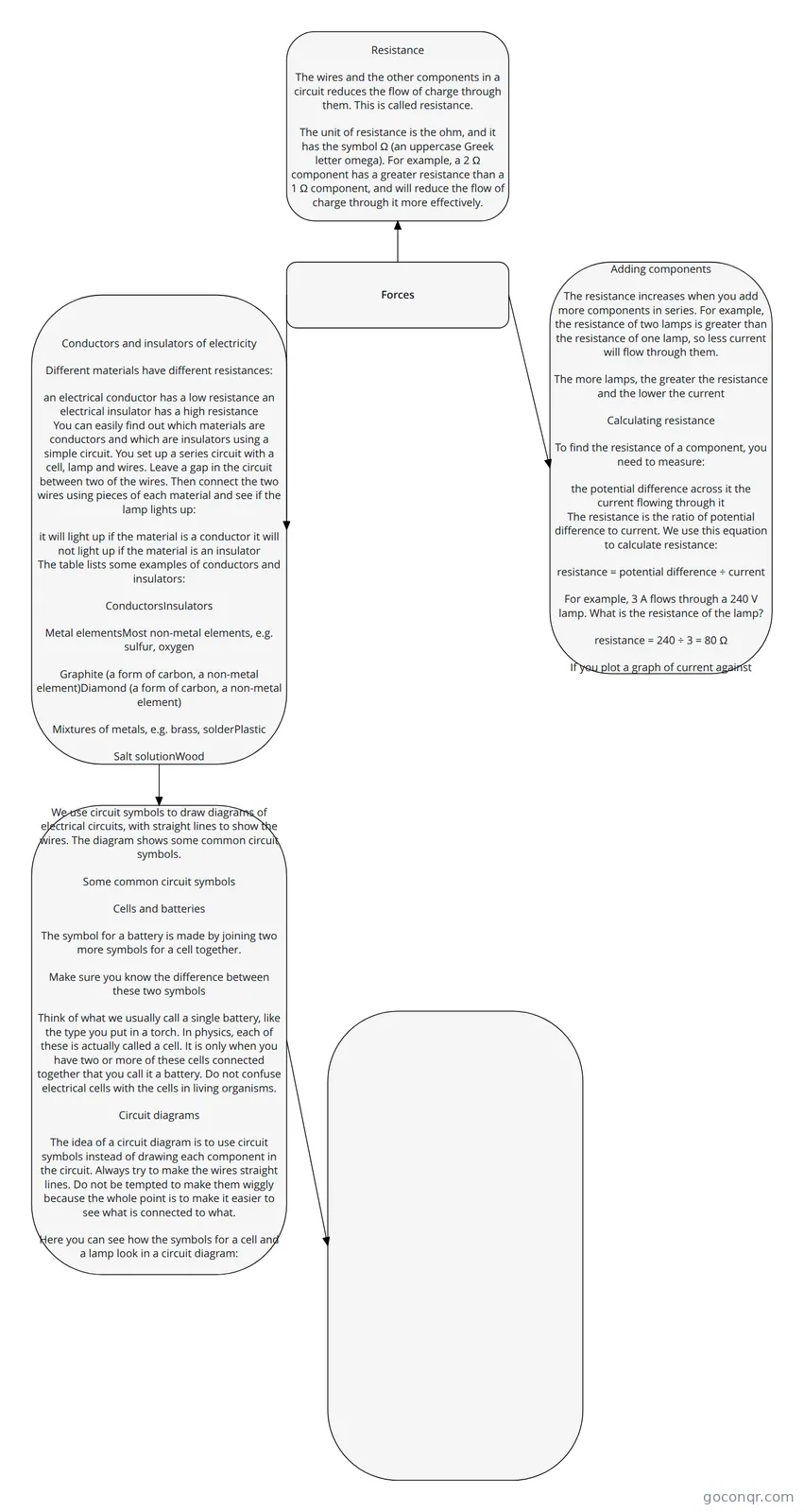
Flowchart: electrical resistance
Inhalt des Flussdiagramms
Forces
Resistance
The wires and the other components in a circuit reduces the flow of charge through them. This is called resistance.
The unit of resistance is the ohm, and it has the symbol Ω (an uppercase Greek letter omega). For example, a 2 Ω component has a greater resistance than a 1 Ω component, and will reduce the flow of charge through it more effectively.
Adding components
The resistance increases when you add more components in series. For example, the resistance of two lamps is greater than the resistance of one lamp, so less current will flow through them.
The more lamps, the greater the resistance and the lower the current
Calculating resistance
To find the resistance of a component, you need to measure:
the potential difference across it
the current flowing through it
The resistance is the ratio of potential difference to current. We use this equation to calculate resistance:
resistance = potential difference ÷ current
For example, 3 A flows through a 240 V lamp. What is the resistance of the lamp?
resistance = 240 ÷ 3 = 80 Ω
If you plot a graph of current against potential difference for a wire, you get a straight line.
Conductors and insulators of electricity
Different materials have different resistances:
an electrical conductor has a low resistance
an electrical insulator has a high resistance
You can easily find out which materials are conductors and which are insulators using a simple circuit. You set up a series circuit with a cell, lamp and wires. Leave a gap in the circuit between two of the wires. Then connect the two wires using pieces of each material and see if the lamp lights up:
it will light up if the material is a conductor
it will not light up if the material is an insulator
The table lists some examples of conductors and insulators:
ConductorsInsulators
Metal elementsMost non-metal elements, e.g. sulfur, oxygen
Graphite (a form of carbon, a non-metal element)Diamond (a form of carbon, a non-metal element)
Mixtures of metals, e.g. brass, solderPlastic
Salt solutionWood
Liquid calcium chlorideRock
We use circuit symbols to draw diagrams of electrical circuits, with straight lines to show the wires. The diagram shows some common circuit symbols.
Some common circuit symbols
Cells and batteries
The symbol for a battery is made by joining two more symbols for a cell together.
Make sure you know the difference between these two symbols
Think of what we usually call a single battery, like the type you put in a torch. In physics, each of these is actually called a cell. It is only when you have two or more of these cells connected together that you call it a battery. Do not confuse electrical cells with the cells in living organisms.
Circuit diagrams
The idea of a circuit diagram is to use circuit symbols instead of drawing each component in the circuit. Always try to make the wires straight lines. Do not be tempted to make them wiggly because the whole point is to make it easier to see what is connected to what.
Here you can see how the symbols for a cell and a lamp look in a circuit diagram:
You could make the circuit by laying out the cell and lamp on the table as shown in the circuit diagram, then joining them using wires
If you have to draw a circuit diagram:
draw the circuit symbols first, then
draw all the wires
If you have to draw wires to join circuit symbols that have been drawn for you already, use a ruler and do not let the wires cross each other.
1
2
3
4
5
6
7
Glossary
More Guides
Static electricity
Electric current and potential difference
Informationen
- Beschreibung
- Flussdiagramm am Forces, erstellt von Catherine Pizzey am 25/05/2019.
- Erstellt von
- Catherine Pizzey
- Aufrufe
- 3
- Bewertung
Mehr zu Resistance and Ohm's Law