
Mindmap
Logic Gates
Inhalt der Mindmap
Logic Gates
They represent digital switches in the CPU
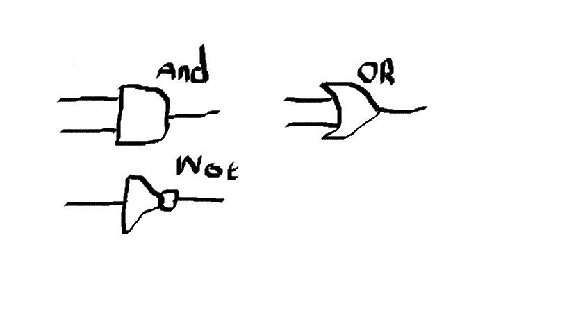
A U represent an OR Gateand a upside down U represents and AND Gate
For an AND Gate, both inputs must be on for the output to be on.
For an OR Gate, only one input or both need to be turned on for the output to be on.
For a NOT Gate, if the input is on then the output is off.
Logic gates can be represented by notation such as Q = A U B would represent Q = A or B
Make sure that all logic gates are clearly drawn differently from each other
When drawing logic gates, whats in brackets goes first in the sequence
Always label inputs and outputs
Always draw the circle on the not gate
A circle after an AND / OR makes it a NAND / NOR
Always use BIDMAS for logic gates
Bilder und Dateien der Mindmap
Informationen
- Beschreibung
- Mindmap am Logic Gates, erstellt von Andrew Neasom am 03/04/2019.
- Erstellt von
- Andrew Neasom
- Aufrufe
- 1
- Bewertung