
Mindmap
SOLAR
Inhalt der Mindmap
SOLAR
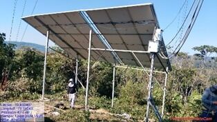
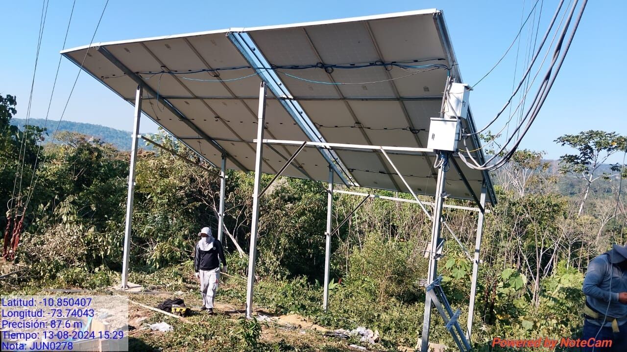
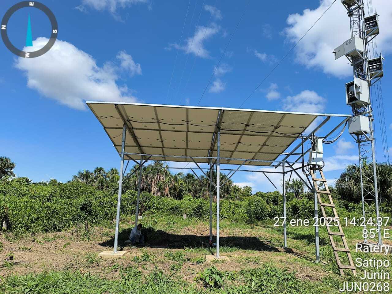
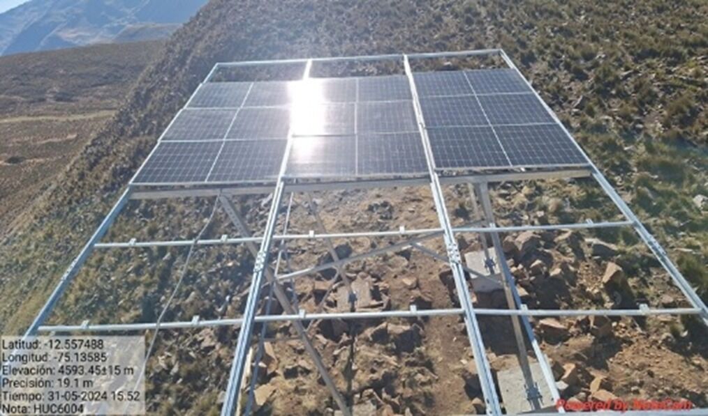
Frame & structure
- Position and Orientation Errors
- Incorrect orientation
- Change orientation to the north side
- Incorrect tilt angle (typically 10° - 35°)
- Adjust the tilt angle according to the geographic location (typically 10° - 35°)
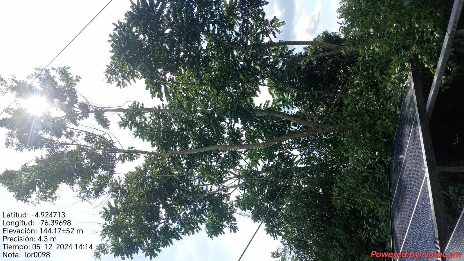
- Shading from surrounding obstacle
- Trim trees, relocate obstacles, or reposition panels to avoid shading
- Incorrect orientation
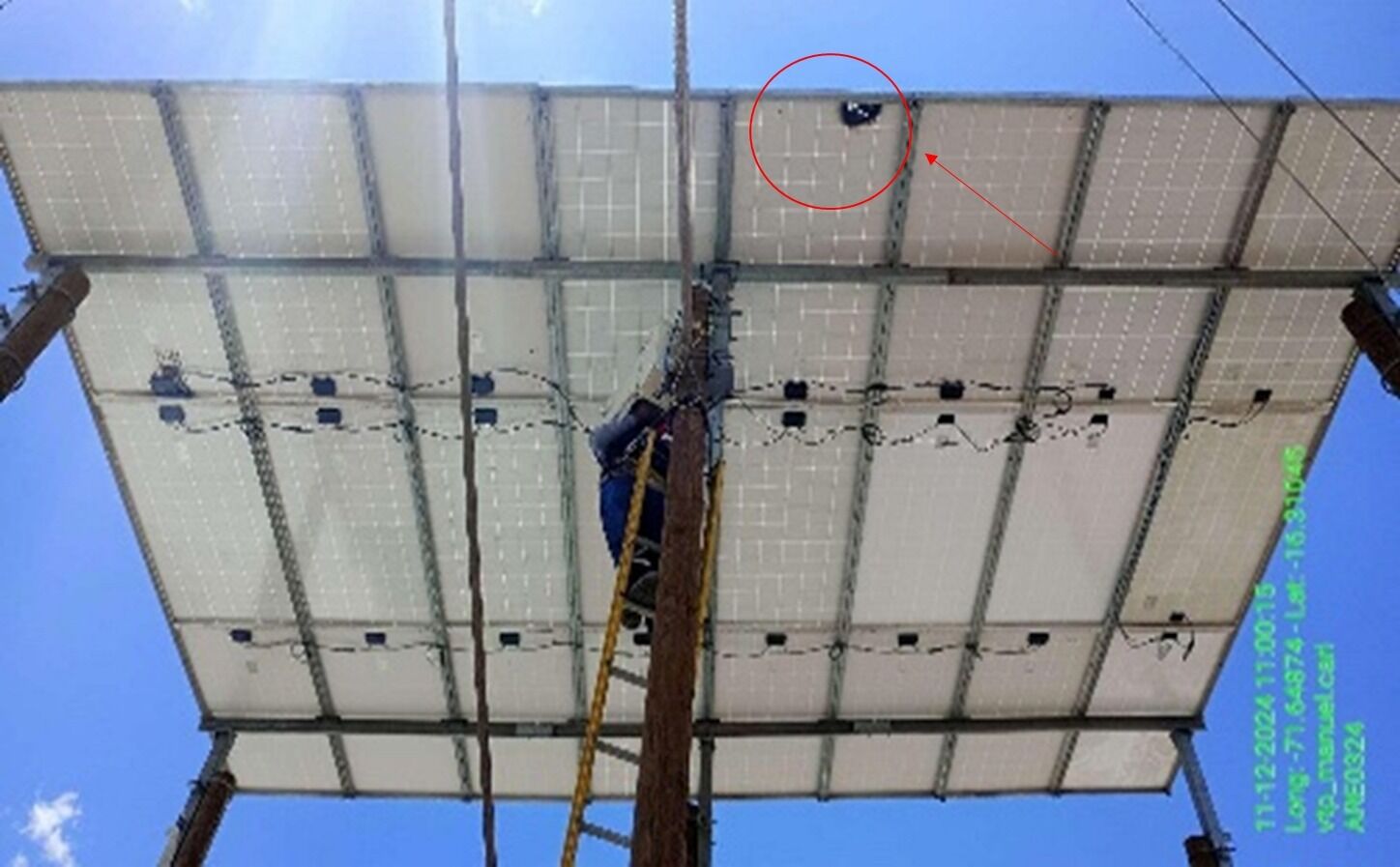
- Structural Frame Errors
- The frame is bent
- Realign the frame to ensure straightness and secure any displaced parts
- Frame not strong enough for wind load
- Reinforce the frame structure or add supports to improve wind resistance
- No grounding system
- Install a proper grounding system in compliance with electrical safety standards
- The frame is bent
- Position and Orientation Errors
Solar Panels
- Mechanical Installation Errors
- Incorrect placement of panel clamps
- Eposition the clamps properly, ensuring they do not damage sensitive parts of the panel
- Loose bolts and nuts
- Tighten bolts and nuts to the required torque specifications
- Incorrect placement of panel clamps
- Electrical System Errors
- Incorrect polarity (+ and -) connections
- Reconnect the cables with the correct polarity according to the wiring diagram
- Faulty or loose connection cables
- Replace damaged cables, tighten loose connections
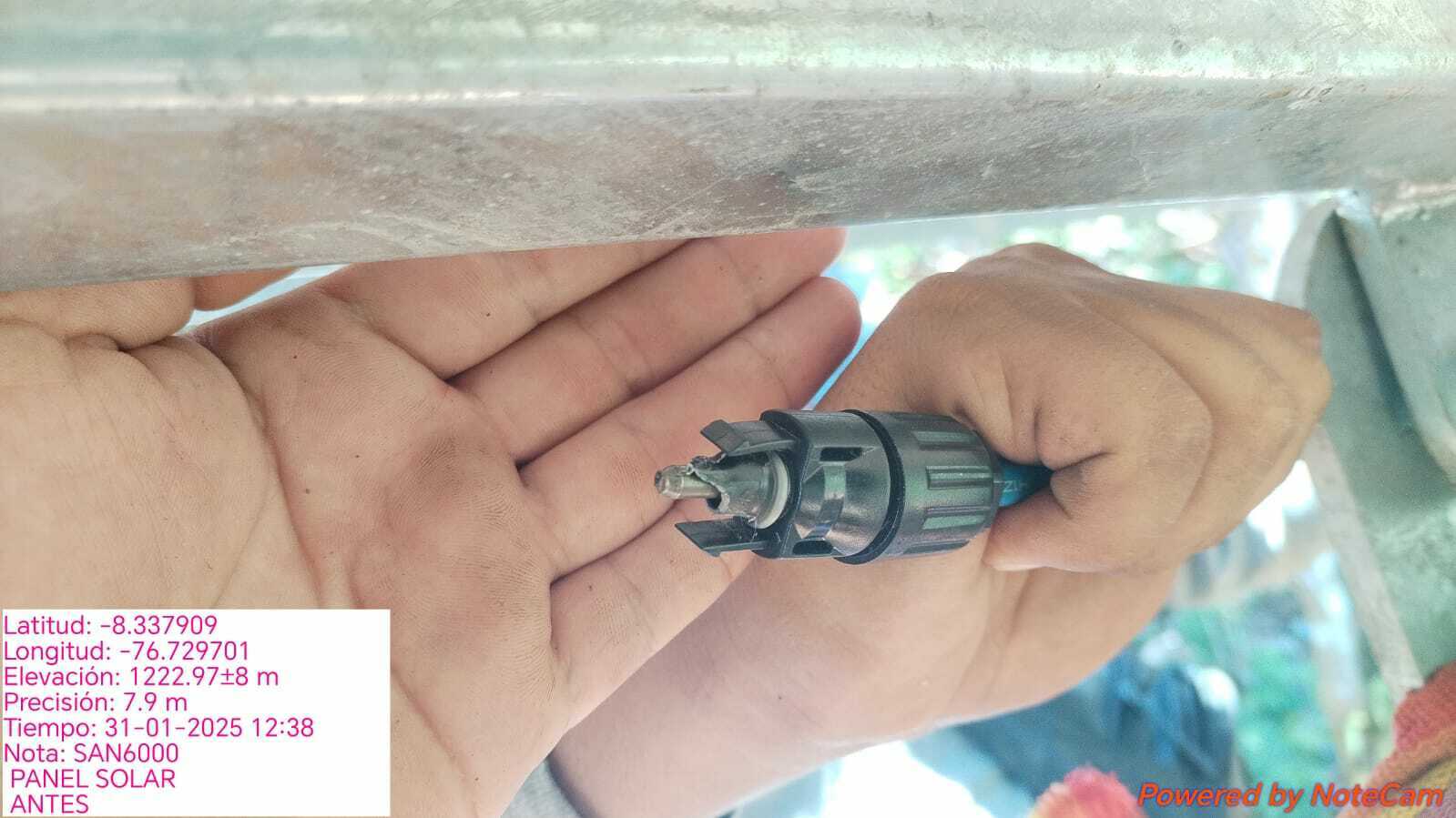
- MC4 burning
- Replace MC4
- Incorrect polarity (+ and -) connections
- Maintenance Errors
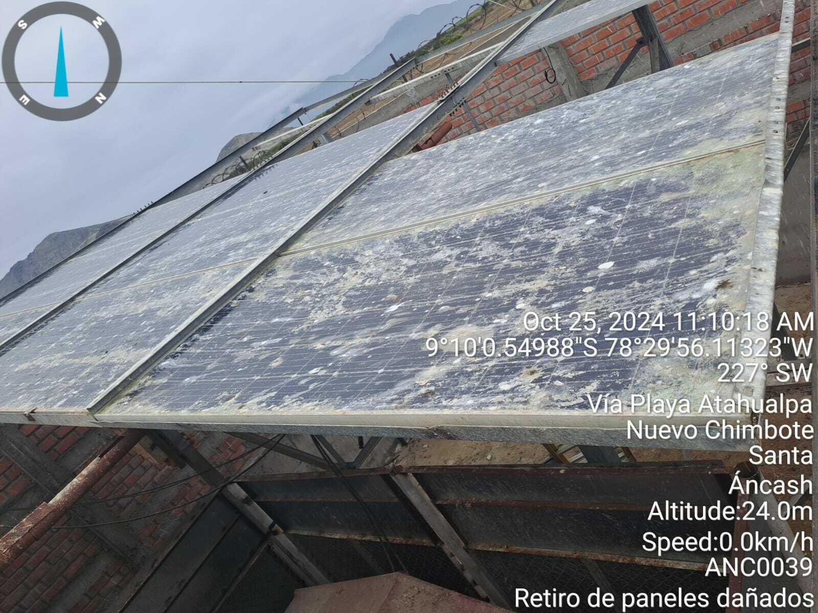
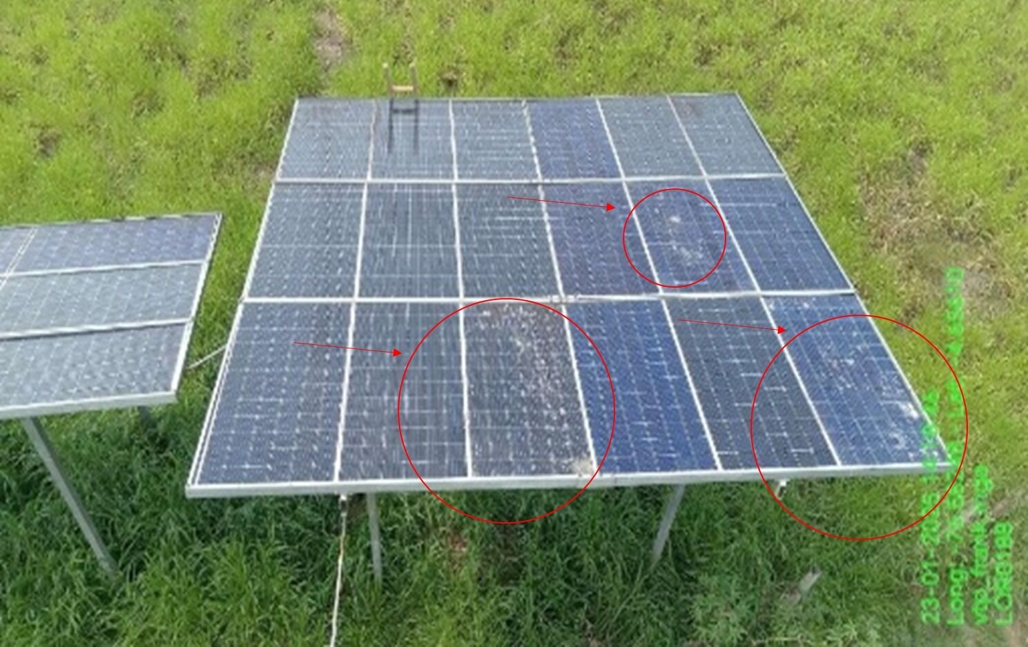
- Dust, bird droppings, or algae
- Clean the panels regularly with water and a soft cloth, avoid harsh chemicals
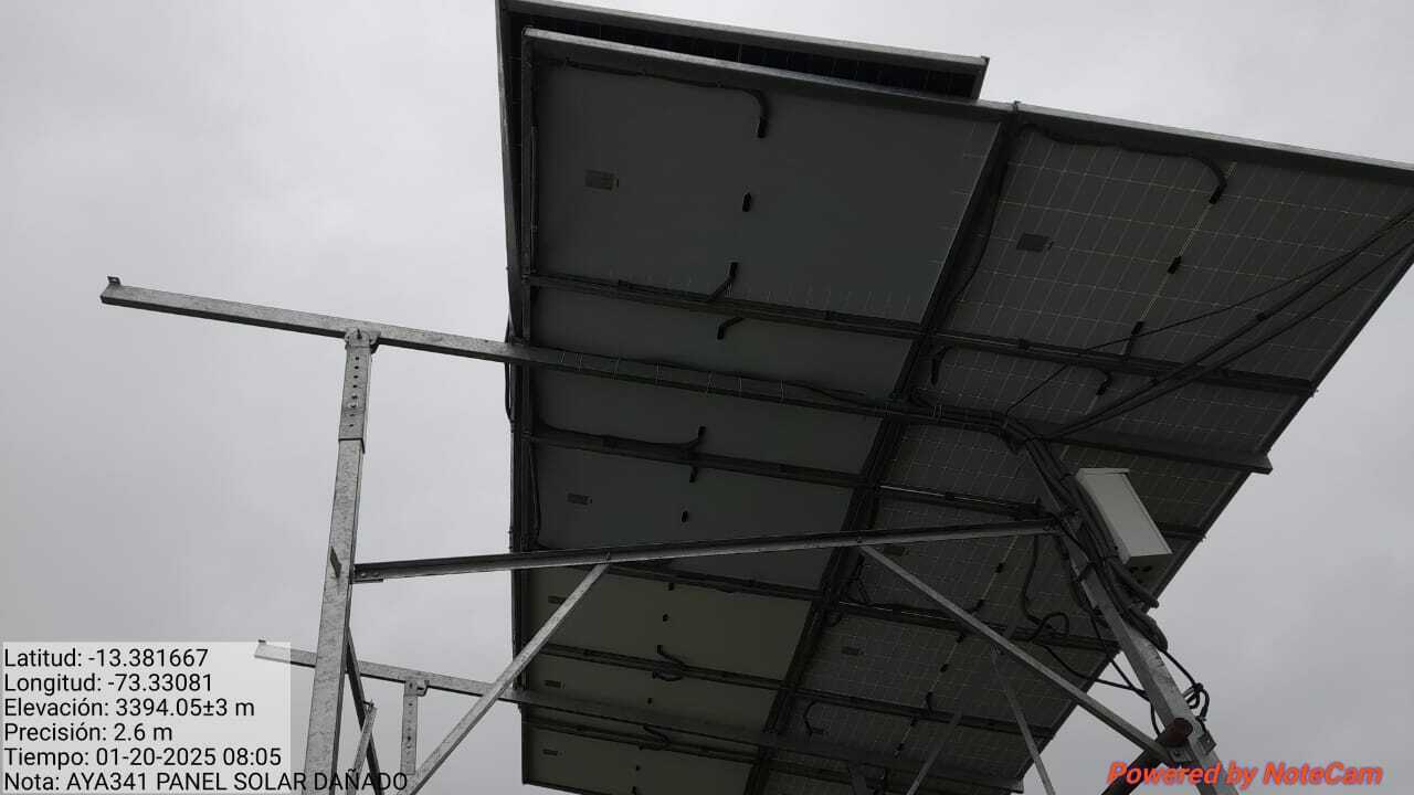
- Failure to detect panel damage, solar crack, broken
- Replace damaged panels or repair them if possible
- Burning solar panel
- Replace
- Dust, bird droppings, or algae
- Mechanical Installation Errors
Solar Box
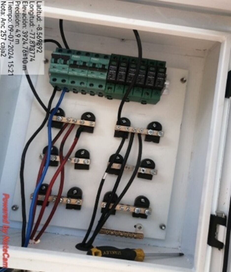
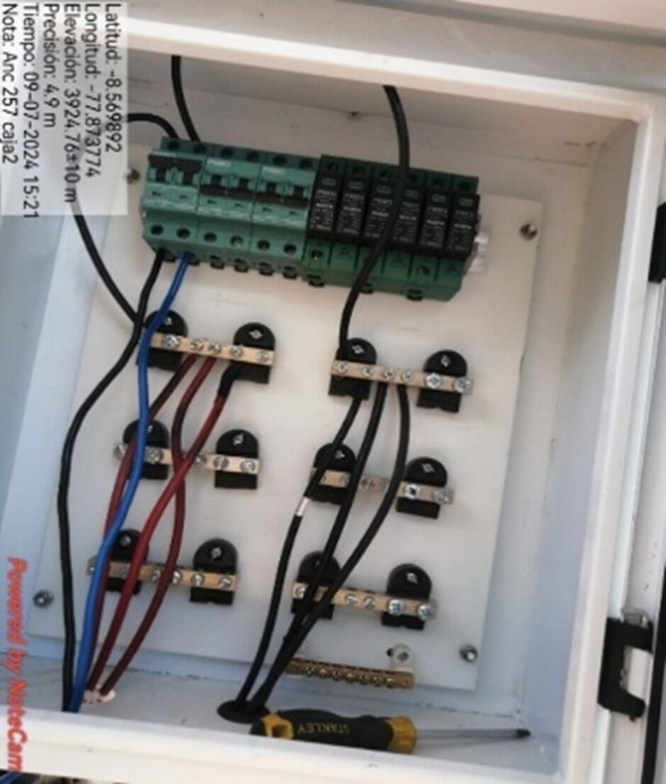
- Electrical Connection Errors
- Loose or insecure connections
- Check each connection point inside the box using a multimeter to measure voltage
- Tighten the connections or replace damaged wire
- Check each connection point inside the box using a multimeter to measure voltage
- Missing Labeling of solar groups.
- Label each solar PU groups
- Incorrect polarity (+) and (-) connections
- Use a voltmeter to check the voltage at connection points
- Reconnect the wires correctly according to the wiring diagram
- Use a voltmeter to check the voltage at connection points
- Damaged or cut wires
- Replace damaged wires or reconnect at the cut points
- Lack of grounding system
- Ground connections must be well made to each SPD to the grounding system.
- Loose or insecure connections
- Material and Quality Issues
- Broken or cracked Solar Box
- Replace the broken or damaged Solar Box with a high-quality one
- Box not securely fastened
- Secure the box firmly with screws or an appropriate protective frame
- Broken or cracked Solar Box
- Electrical Connection Errors
Battery
- Battery Lifespan Issues
- Difrent type of battrery
- Change the same model (shoto, ZTT or VMC)
- Battery swelling or bloating
- Visually inspect the battery or feel for swelling signs
- Replace the swollen battery immediately, avoid using a swollen battery
- Visually inspect the battery or feel for swelling signs
- No light run battery, Battery has red Alarm
- Push reset battery, measure Voltage and Current of DC
- Voltage, Current = 0
- Replace Battery
- Voltage, Current = 0
- Push reset battery, measure Voltage and Current of DC
- Capacity Battery lack
- Calculator number battery need follow load
- Add more battery
- Calculator number battery need follow load
- Stolen Battery
- Request Branch Police report to Shiftleader
- Reinforce battery cabinet and install new battery
- Request Branch Police report to Shiftleader
- Incorrect battery capacity configuration
- Check the settings on the DC power cabinet
- Change battery capacity setting according to CB
- Check the settings on the DC power cabinet
- Difrent type of battrery
- Connection and Cable Issues
- Loose connection cables
- Check all connections between the battery and device by gently pulling on the cables
- Tighten all connectors, replace cables if damaged
- Check all connections between the battery and device by gently pulling on the cables
- Damaged connection cables
- Inspect the entire wiring system and connection cables
- Replace damaged cables or reconnect them to ensure uninterrupted current flow
- Inspect the entire wiring system and connection cables
- Bad Battery connection
- Battery connections must be in parallel
- Loose connection cables
- Battery Lifespan Issues
5.- DC System
- SPD
- Burning
- Replace
- Damage
- Color of "indicator" is RED
- Change SPD
- Color of "indicator" is RED
- Burning
- Wrong Electrical connections
- Negative cable (blue) to CB, positive cable (black/red) to positive bus or PT
- Cables must be properly adjusted
- CSU
- Alarm red in CSU
- PU Communication Fail#4, PU have red Alarm
- Burning
- Replace
- PU not working
- Change slot PU, Check Voltage Input of PU 70-130
- PU Not working
- Replace PU
- PU Working
- Change slot PU
- PU Not working
- Change slot PU, Check Voltage Input of PU 70-130
- Burning
- Battery Loop Broken#1
- Sensor disconnected
- Reconnect sensor
- Bad configuration of Capacity breaker
- Set capacity according quantity of batteries
- Breaker empty
- Turn off
- CB Battery off
- Turn on
- Sensor disconnected
- SMR Communication Fail
- Red alarm rectifier
- Burn
- See phisically is broken or burned internally
- Replace Rectifier
- See phisically is broken or burned internally
- Check "Work mode"
- Set in "Free mode"
- Recitfier not Working
- Test in other slot
- Recitfier not Working
- Change rectifier
- Recitfier not Working
- Test in other slot
- Recitfier not Working
- Set in "Free mode"
- Alarm Rectifier Overload
- Caculator add more rectifier
- Burn
- Red alarm rectifier
- PU Communication Fail#4, PU have red Alarm
- Not Mornitoring DC cabinet
- Mornitoring DC
- Config wrong parameter in CSU
- Battery Capacity
- Only define Batt capacity at the connected battery_CB
- Battery Shunt
- Set to 300 mV
- Float Charge Voltage
- 53.2 V, Enable
- Equalized Charge Voltage
- 56.4 V, Enable
- LLVD1 Voltage
- 45 V, Enable
- LLVD2 Voltage
- 44.5 V, Enable
- BLVD Voltage
- 44 V, Enable
- Battery Capacity
- Burning
- Replace
- Alarm red in CSU
- Breaker
- AC
- Measure with Multimeter Output Voltage in 0VAC
- Turn off and turn on again, not turn on
- Replace CB
- Turn off and turn on again, not turn on
- Measure with Multimeter Output Voltage in 0VAC
- Load
- Load no connected
- Turn off the not used breaker
- Measure with Multimeter Output Voltage in 0VAC
- Check again
- Load no connected
- Burning
- Replace
- AC
- SPD
6.-Generator
- Imformation of generator
- Power, 1P/3P, Vendor, Gasoline/Diesel
- The last maintainance
- Quality maintainance
- The last time run generator
- Total time run generator 1 day in netnument
- Battery Generator
- Battery low power
- Check battery voltage with a multimeter (below 12V indicates a weak battery).
- Recharge the battery or replace it if it's worn out.
- Check battery voltage with a multimeter (below 12V indicates a weak battery).
- Battery casing cracked or leaking acid
- Replace the battery to prevent safety hazards.
- Battery swollen or deformed
- - Stop using immediately and replace the battery.
- Loose or corroded battery terminals
- - Clean battery terminals with a specialized cleaner. - Tighten battery terminal connections.
- Battery low power
- Check alarm in CSU
- Fail to start Alarm
- Lack of fuel
- Refill fuel
- Clogged fuel filter or faulty fuel pumpl
- Generator does not start or stalls after a short run.
- - Inspect and clean or replace the fuel filter. - Check the fuel pump and fuel lines for blockages.
- Generator does not start or stalls after a short run.
- Starter system failure (relay, faulty starter motor)
- - No response when pressing the start button, Or Clicking sound ("tick tick") but no engine rotation
- - Check the starter relay and wiring connections. - Replace the starter motor if defective.
- - No response when pressing the start button, Or Clicking sound ("tick tick") but no engine rotation
- Lack of fuel
- Fail to start Alarm
- Imformation of generator
Check solar panel in system software
- Imformation station
- Name station, Problem of stie, Type of energy, Power consumption max, status.
- Number Solar panel, Number battery
- Check information interruption history
- Number of days of information interruption per week?
- Number of cells*h in a week?
- Regular maintenance
- Last maintenance date
- Quality of maintenance
- Maintenance cycle
- Check for sizing solar
- Check design with station load current
- Give Soltuion Short Term
- Check design with max load
- Give solution long term
- Check design with station load current
- Mornitoring
- Not mornitoring
- Connection mornitoring
- Have mornitoring
- Check current, Voltage Input and Output of PU
- Compare Voltage and Curent of PU, if Voltage out range 70-140
- Suspected PU fault or solar panel needs replacement
- TM come to site check
- Suspected PU fault or solar panel needs replacement
- Compare Voltage and Curent of PU, if Voltage out range 70-140
- Check Warning of device
- Alarm PU Communication Fail#4, Battery Loop Broken#1, SMR Communication Fail
- Suspected PU fault or solar panel needs replacement
- TM come to site check
- Suspected PU fault or solar panel needs replacement
- Alarm PU Communication Fail#4, Battery Loop Broken#1, SMR Communication Fail
- Check config of Parameter
- Wrong parameter Battery Capacity, Battery Shunt, Float Charge Voltage, Equalized Charge Voltage, Battery Charge Current Coefficient, LLVD1 Voltage, LLVD2 Voltage, BLVD Enabled
- Change config
- Wrong parameter Battery Capacity, Battery Shunt, Float Charge Voltage, Equalized Charge Voltage, Battery Charge Current Coefficient, LLVD1 Voltage, LLVD2 Voltage, BLVD Enabled
- Check current, Voltage Input and Output of PU
- Not mornitoring
- Imformation station
Bilder und Dateien der Mindmap
Informationen
- Beschreibung
- Mindmap am SOLAR, erstellt von Luis Arturo Membrillo Pillpe am 27/01/2025.
- Erstellt von
- Luis Arturo Membrillo Pillpe
- Aufrufe
- 17
- Bewertung