
Diagrama de flujo
NEA manufacturing plan
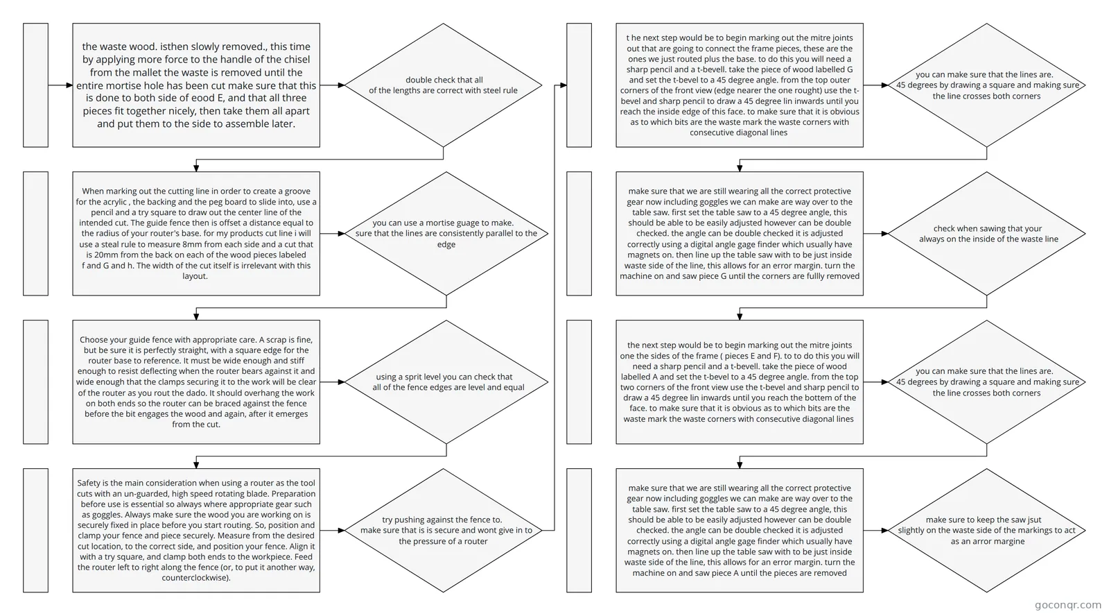
Flowchart: NEA manufacturing plan
Contenido del diagrama
double check that all of the lengths are correct with steel rule
When marking out the cutting line in order to create a groove for the acrylic , the backing and the peg board to slide into, use a pencil and a try square to draw out the center line of the intended cut. The guide fence then is offset a distance equal to the radius of your router's base. for my products cut line i will use a steal rule to measure 8mm from each side and a cut that is 20mm from the back on each of the wood pieces labeled f and G and h. The width of the cut itself is irrelevant with this layout.
you can use a mortise guage to make. sure that the lines are consistently parallel to the edge
Choose your guide fence with appropriate care. A scrap is fine, but be sure it is perfectly straight, with a square edge for the router base to reference. It must be wide enough and stiff enough to resist deflecting when the router bears against it and wide enough that the clamps securing it to the work will be clear of the router as you rout the dado. It should overhang the work on both ends so the router can be braced against the fence before the bit engages the wood and again, after it emerges from the cut.
using a sprit level you can check that all of the fence edges are level and equal
t he next step would be to begin marking out the mitre joints out that are going to connect the frame pieces, these are the ones we just routed plus the base. to do this you will need a sharp pencil and a t-bevell. take the piece of wood labelled G and set the t-bevel to a 45 degree angle. from the top outer corners of the front view (edge nearer the one rought) use the t-bevel and sharp pencil to draw a 45 degree lin inwards until you reach the inside edge of this face. to make sure that it is obvious as to which bits are the waste mark the waste corners with consecutive diagonal lines
make sure that we are still wearing all the correct protective gear now including goggles we can make are way over to the table saw. first set the table saw to a 45 degree angle, this should be able to be easily adjusted however can be double checked. the angle can be double checked it is adjusted correctly using a digital angle gage finder which usually have magnets on. then line up the table saw with to be just inside waste side of the line, this allows for an error margin. turn the machine on and saw piece G until the corners are fullly removed
the next step would be to begin marking out the mitre joints one the sides of the frame ( pieces E and F). to to do this you will need a sharp pencil and a t-bevell. take the piece of wood labelled A and set the t-bevel to a 45 degree angle. from the top two corners of the front view use the t-bevel and sharp pencil to draw a 45 degree lin inwards until you reach the bottem of the face. to make sure that it is obvious as to which bits are the waste mark the waste corners with consecutive diagonal lines
you can make sure that the lines are. 45 degrees by drawing a square and making sure the line crosses both corners
check when sawing that your always on the inside of the waste line
you can make sure that the lines are. 45 degrees by drawing a square and making sure the line crosses both corners
Safety is the main consideration when using a router as the tool cuts with an un-guarded, high speed rotating blade. Preparation before use is essential so always where appropriate gear such as goggles. Always make sure the wood you are working on is securely fixed in place before you start routing. So, position and clamp your fence and piece securely. Measure from the desired cut location, to the correct side, and position your fence. Align it with a try square, and clamp both ends to the workpiece. Feed the router left to right along the fence (or, to put it another way, counterclockwise).
try pushing against the fence to. make sure that is is secure and wont give in to the pressure of a router
make sure that we are still wearing all the correct protective gear now including goggles we can make are way over to the table saw. first set the table saw to a 45 degree angle, this should be able to be easily adjusted however can be double checked. the angle can be double checked it is adjusted correctly using a digital angle gage finder which usually have magnets on. then line up the table saw with to be just inside waste side of the line, this allows for an error margin. turn the machine on and saw piece A until the pieces are removed
make sure to keep the saw jsut slightly on the waste side of the markings to act as an arror margine
the waste wood. isthen slowly removed., this time by applying more force to the handle of the chisel from the mallet the waste is removed until the entire mortise hole has been cut make sure that this is done to both side of eood E, and that all three pieces fit together nicely, then take them all apart and put them to the side to assemble later.
Información
- Descripción
- Diagrama sobre NEA manufacturing plan, creado por ruby waller el 01/03/2022.
- Creado por
- ruby waller
- Visitas
- 4
- Valoración