9830339
Description
Flashcards by Simon Leblanc, updated more than 1 year ago
|
|
Created by Simon Leblanc
over 6 years ago
|
|
| Question | Answer |
| Exhaust Temperatures | Light: 600-700 F Idle: 800-900 F WOT: 1600-1700 F The Te increases as we increase velocity since the F/a density increases and it releases more heat |
| Heat Energy Distribution | Power: 30% Exhaust: 30% Friction Loss: 10% Coolant: 30% However, as RPM increases, 50% goes into exhaust |
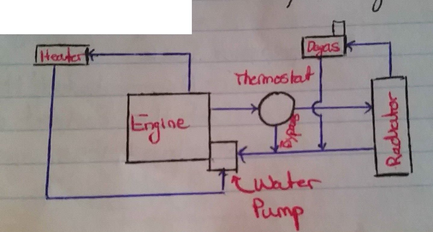
| Cooling System Essential Components | Water Jackets Water Pump Cooling Fan Coolant Heater Core Expansion Tank Radiator Thermostat Operates between 185-205 F |
| Thermostat; Details & Purposes | Purpose: To speed up engine warm up and control the operating temperatures Details: Near 185 F it opens and around 205-218 F it is wide open (T.W.O.). Contains a bypass between engine and radiator |
| Coolant; Purpose & Additives | Purpose: Fluid to transfer heat Additives: Ethylene Glycol (increases boiling point, reduces f.p., prevents rust). 50/50 is recommended. (60-67% for extreme cold areas) Higher viscosity = Lower thermal conductivity and specific heat (<50% h.t.) |
| Coolant Pump; Details | Machine that adds energy to a fluid (liquid) Operates at 4500-5000 rpm Can reach 150 gpm |
| Cooling fan; Purpose & Details | Purpose: Ensures good air flow in the radiator at low speeds Details: RWD uses 4 blades (5-6 if A/C) FWD uses 1-2 electric fans |
| Radiator; Purpose & Types | Purpose: Transfer heat from coolant into the air by forced convection Types: Downflow - Distributes coolant evenly but needs a higher hood line Crossflow - Side to side flow |
| Heater Core; Purpose | Purpose: To heat the cabin of a car It is a tiny radiator |
| Gas moving machines (with flow characteristics) | Fan: Low pressure rise & high flow rate Blower: Moderate pressure & flow rate Compressor: High pressure rise & low flow rate |
| Horsepower; Water and Brake | Water Horsepower: Useful power delivered by the pump to the fluid. Proportional to the net head. Brake Horsepower: Power delivered to the pump in order to compensate for losses due to friction, leaks, etc... |
| Pump Operating Point | Intersection between the pump and system performance curves. (Pump Performance vs. System resistance) |
| Head increases due to... | Too long of a pipe |
| Pressure Loss increases due to... | Friction losses Cooler coolant (higher viscosity) Thermostat position (closed) Age Flow characteristic (laminar vs. turbulent) |
| Increasing Pump RPM causes... | Higher flow rate Higher pressure head (lower inlet, high outlet pressures) |
| Cavitation in a Pump | When the NPSH required is higher than that available by the pump; causing bubbles in the fluid. (Intersection: The maximum volume flow rate that the pump can deliver) |
| To avoid Cavitation | Ensure suction pressure (P in) is greater than the saturation pressure (P vapor). If pump is too big --> Cavitation If pump is too small --> Not enough flow |
| Sizing a Pump; Needed information | 1. Engine HP & Torque curves 2. Engine full load heat rejection 3. Pump Curves 4. Air & Coolant side heat transfer 5. Ram air flow (air in without fan) 6. Fan performance 7. Automatic transmission heat rejection |
| Boiling vs. Evaporation | Boiling: The liquid to solid interface Pool- Natural convection & bubbles (no motion) Flow- External means (ie. Pump) (motion) Evaporation: The liquid to gas interface Dry air absorbs the liquid molecules |
| When inner tube wall temperature > critical flux temperature... | 1. Physical Damage 2. Decrease of lubrication film 3. Higher fuel consumption 4. Thermal decomposition |
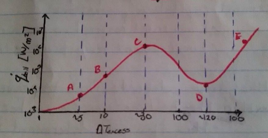
| A-B: Convection (no bubbles) B-C: Nucleate Boiling (small visible bubbles) C-D: Critical Heat Flux (At pt. D, Higher wall Temperature = Lower heat transfer) D-E: Transition Boiling Zone E-F: Film Boiling Regime (Not tolerated in engines) | |
| To reach required flow rate... | 1. Reduce hydraulic resistance (ie. hose bends) 2. Increase pump output 3. Decrease flow requirements |
| Thermostat Curves | Open: Should be at BEP Closed: Flow rate no less than 80% of open (BEP) flow rate |
| Radiator; Design & Considerations | As square as possible (optimal "footprint") Coolant velocity between 2~3 - 10 ft/s (too low leads to scale formation) Exist temperature between Air & Coolant is 15~20 F (if less than radiator is oversize or path is too long) |
| Types of Extended Surfaces | 1. Tube and Plate fin (heavy trucks) Max FPI = 14 or less 2. Tube and Spacer (cars and light trucks) Max FPI = 21 |
| How to Improve Duty of a Radiator | Increase the FPI (Fins per Inch), leading to an increase in Outside Surface Area |
| Materials of a Radiator | Brass/Copper: Copper transfers heat well but is brittle (ie. Easily damaged) Aluminum: Lighter (1/3rd), no lead to join Cheaper (less efficient) Can use thicker cores |
| Rating vs. Sizing | Rating: Evaluating performance when size is specified (ie. e-NTU) Sizing: Determining the dimensions of a HEX to meet specified performance (ie. LMTD or e-NTU) |
| How to improve heater transfer coefficient of the coolant ('h'i) | 2 pass will have higher velocity, leading to turbulent flow (rather than laminar) However, as rows increases, pressure drop increases and the temperature between air and coolant decreases.. (2 is typical) |
| Assumptions made in Radiator Calculations | 1. Cross-flow with 2 unmixed fluids 2. Correction factor ~ 1 3. Uniform flow (in reality, false because of A/C heat load resistance, radiator grill) |
| Dimples in Tubes | Holes used to create turbulence by breaking the boundary layer (more effective at low Reynolds, because at high velocity it is already turbulent) |
| Air Side Boundary Layer | Thinner the better (it is resisting the heat transfer) Add louvers; creates discontinuities on the surface (3-4x more h.t. and increases pressure drop and friction thus needs a bigger fan) |
| Heat Exchangers; Required for Fin Density | 1. 16 to 18 FPI common in 2 row rads 2. Less FPI if core is thicker (4 row ~ 12 FPI) 3. Airflow is a function of pressure drop and radiator density (High pressure drop can lead to no possible air flow) 4. Good exit flow (2 row rad w/ poor exit flow = 4 row w/ good exit flow) |
| Vehicle to Radiator Air Velocity | Radiator inlet velocity ~ 30-40% Car Speed Airside heat transfer coefficient 'h'f = 38 x sqrt(V_car) |
| Purpose of Engine Cooling System | 1. Remove excess heat from the engine 2. Maintain the correct temperature 3. Get to the correct temperature ASAP |
| Air Conditioning Components; Major | 1. Compressor 2. Evaporator 3. Expansion Valve 4. Condenser |
| Air Conditioning Components; Minor | 1. Accumulator 2. Receiver 3. Magnetic Clutch 4. Filter 5. Oil Separator |
| Radiator Model Temperature Guidelines | Maximum air temp out of radiator ~ 190 F Maximum under-hood temp ~ 225 F |
| Viscous Coupling | A fluid movement causes another component to move |
| Condenser and Evaporator | Condenser: In front of engine radiator Evaporator: Beside heater core assembly (dash board of the vehicle) Refrigerant enters evap. tube with low fraction as vapor, and becomes vaporized. (NOTE: Graph, not bell-curve of "Along Evaporator vs. Heat Transfer Coefficient 'h' " |
| A/C compressor; Purpose & Operating Point | 1. Compress gas refrigerant from low to high pressure 2. Pump refrigerant through condense, flow device and evaporator Operating Point: Intersection of compressor RPM and refrigerant system |
| Expansion Valve; Purpose & Details | Purpose: Throttles and Modulates/Controls Details: Meters the systems needs to maintain cooling, modulates from W.O. to closed. (Separates the high side to the low side) |
| Scroll & Piston Compressor; Displacements (ie. Fixed, Variable, Variable Capacity Scroll), Details | Fixed: 6.1 - 12.6 cubic inches Variable: 1 - 10 cubic inches Variable Capacity Scroll: Max of 7.3 cubic inches with a minimum of ~3% of max Details: Sustain 500-6000 RPM, CR of 5:1 - 8:1, any higher increases piston load and breaks down oil (High Temp). Driven by crankshaft |
| Vehicle Operating Conditions; 2 major operating curves & How to size the radiator | 1. Peak Torque Curves 2. Peak HP Curves Sizing the radiator at the peak HP can protect engine at any driving condition. (May be costly due to higher design) |
| Transmission; Heat loss of Oil, Slip | 65% of heat loss by transmission is absorbed by the coolant Transmission slip: Difference of input and output RPM of the transmission |
| Conditioned Air | Typically: 15~17 C, 200~300 CFM The A/C outlet location and flow rate influence thermal comfort |
| Thermal Comfort; Definition | Humans do not feel temperature, we feel energy loss from the body. Cooling load in vehicles is heat from solar radiation and in buses, heat from people. |
| Thermal Comfort; Influencing Factors | 1. Insulating Factor: Clothing 2. Physiological Factor: Age, Activity, Health 3. Environmental Factor: Air temp, Mean radiant temp, humidity, air velocity |
| Air Management System; Sections | 1. Air intake 2. Heater and A/C evaporator (Plenum) 3. Air distribution section |
| Air Conditioning System; Cooling Capacity | Total flow rate into passenger compartment is crucial in transient cool down (less important in steady-state) Typically, over estimate cooling capacity for quick cooling. |
| Coolant Flow Schematic |
Want to create your own Flashcards for free with GoConqr? Learn more.