Internal and external communication

Description

Mind Map on Internal and external communication, created by Daniel Lugo on 13/11/2015.
Daniel Lugo
Mind Map by Daniel Lugo, updated more than 1 year ago
Daniel Lugo
Created by Daniel Lugo about 10 years ago
18
0

Resource summary

Internal and external communication
  1. Port
    1. Is a connection
      1. Is used to conect some devices
        1. Allows exchange data
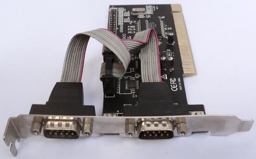
          1. Serial Ports
            1. Asynchronous adapter
              1. Intercomunicar several computers together
                1. Receives and sends information
                  1. 25 pin
                    1. Serial interface connector
                      1. DTE (Data terminal Equipment)
                        1. DCE (Data Comunication Equipment)
                          1. 1 Pin - P.G. - Safety Ground
                            1. 2 Pin - TD -> DCE - DTE output
                              1. 3 Pin - RD -> DTE - DTE input data
                                1. 4 Pin RTS -> DCE - Request to Send DTE
                                  1. 5 Pin - CTS -> DTE - DCE ready to transmit
                                    1. 6 Pin - DSR-> DTe - CE ready to com . DTE
                                      1. 7 Pin - GND - Common ground circuit
                                        1. 8 Pin - DCD -> DTE - Stopping carrier
                                          1. 20 Pin - DTR -> DCE - Terminal Signal available
                                            1. 23 Pin - DSRD - Speed ​​indicator TX
                                              1. COM1 and COM2
                                                1. Chip UART
                                                  1. Communication in one direction
                                                    1. Used addresses and a signal line
                                                    2. Parallel Port
                                                      1. I/O
                                                        1. Type D-25
                                                          1. 25 Pin
                                                          2. It is used by printers
                                                            1. LPT (online printer)
                                                              1. DB25
                                                                1. Socket
                                                                  1. 36 Pin
                                                                  2. 8 bits = 1 byte
                                                                    1. 5 inputs "Steady-State Input points"
                                                                      1. DATA
                                                                        1. STATUS
                                                                          1. CONTROL
                                                                            1. 17 signal lines and 8 ground lines
                                                                              1. 4. Control lines
                                                                                1. 5. state lines
                                                                                  1. 8. Data lines
                                                                              Show full summary Hide full summary

                                                                              Similar