Description
|
|
Created by Isaac Farias
over 8 years ago
|
|
Page 1
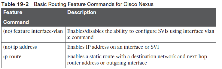
When routers and Layer 3 switches configure IP addresses on their interfaces, the device knows about the subnets connected, based on what has been configured. The devices then use these subnets to build a routing table for any subnet that is directly connected to one of its interfaces. Although Cisco Nexus switches enable IPv4 routing globally, you must enable particular routing features in Nexus L3-enabled products to enable the appropriate feature
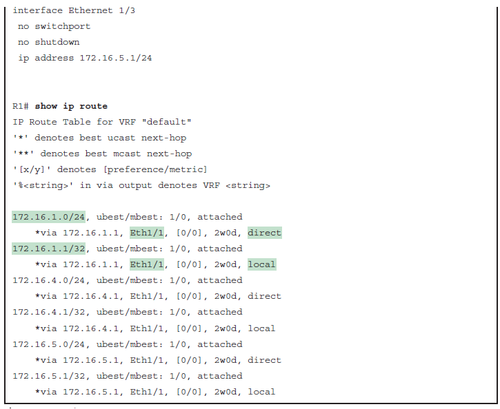
To make the router be ready to route packets on a particular interface, the router must be configured with an IP address, and the interface must be configured such that it comes up, reaching a “line status up, line protocol up” state.Routers can add routes to their routing tables through three methods:■ Connected routes: Added because of the configuration of the ip address interface subcommand on the local router■ Static routes: Added because of the configuration of the ip route global command on the local router■ Routing protocols: Added as a function by configuration on all routers, resulting in a process by which routers dynamically tell each other about the network so that they all learn routes.Direct and Local Routes and the ip address Command A Cisco Nexus L3 switch automatically adds two routes to its routing table based on theIPv4 address configured for an interface, assuming that the following two facts are true:■ The interface is in a working state—in other words, the interface status in the show interfaces command lists a line status of up and a protocol status of up. ■ The interface has an IP address assigned through the ip address interface subcommand.The two routes, called a direct and a local route, route packets to the subnet directly connected to that interface. The router, of course, needs to know the subnet number used on the physical network connected to each of its interfaces, so the router can route packets to that subnet. The router can simply do the math, taking the interface IP address and mask, and calculate the subnet ID.
Page 3
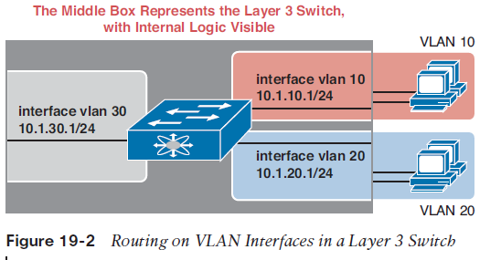
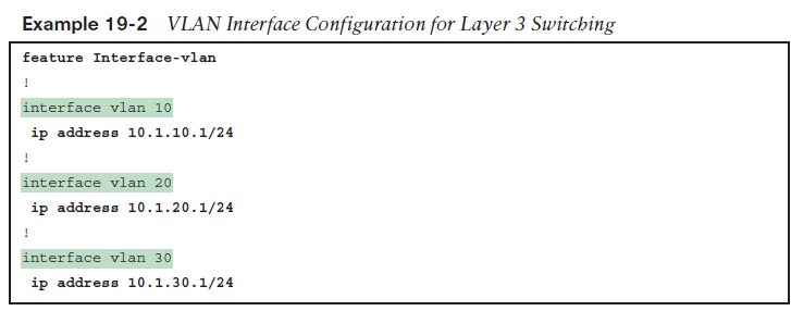
Focus on the lists with highlights, which focus on the direct and local routes related to R1’s E1/1 interface. First, the output shows a route to subnet 172.16.1.0/24—the subnet off R1’s E1/1 interface—with an ending word of direct. This route represents the entire directly connected subnet. R1 will use this route when forwarding packets to other hosts in subnet 172.16.1.0/24.In the configuration in Example 19-1, notice the no switchport command, which is highlighted under each Ethernet interface. You learned in Chapter 18, “IPv4 Routing Concepts,” that there are two ways to configure routing on a Cisco Nexus switch:■ A routed interface, which is enabled by using the no switchport command. Remember that when using this command, we are disabling any Layer 2 functionality on an interface.■ Switched virtual interface (SVI), which you use when you route between VLANs and support Layer 2 with Layer 3 simultaneously.Routing Between Subnets on VLANsAlmost all enterprise networks use VLANs. To route IP packets in and out of thoseVLANs—or more accurately, the subnets that sit on each of those VLANs—some routerneeds to have an IP address in each subnet and have a connected route to each of those subnets.Then the hosts in each subnet can use the router IP addresses as their default gateways,respectively.Three options exist for connecting a router to each subnet on a VLAN. However, the firstoption requires too many interfaces and links, and is mentioned only to make the listcomplete:■ Use a router, with one router LAN interface and cable connected to the switch for eachand every VLAN (typically not used).■ Use a router, with a VLAN trunk connecting to a LAN switch.■ Use a Layer 3 switch.Configuring Routing to VLANs Using a Layer 3 SwitchThe configuration of a Layer 3 switch mostly looks like the Layer 2 switching configuration,with a small bit of configuration added for the Layer 3 functions. The Layer 3 switchingfunction needs a virtual interface connected to each VLAN internal to the switch. TheseVLAN interfaces act like router interfaces, with an IP address and mask. The Layer 3 switchhas an IP routing table, with connected routes off each of these VLAN interfaces. (Theseinterfaces are also referred to as SVIs.)Figure 19-2 shows the Layer 3 switch function with a router icon inside the switch, toemphasize that the switch routes the packets. The datacenter has three server VLANs, so theLayer 3 switch needs one VLAN interface for each VLAN.
Page 4
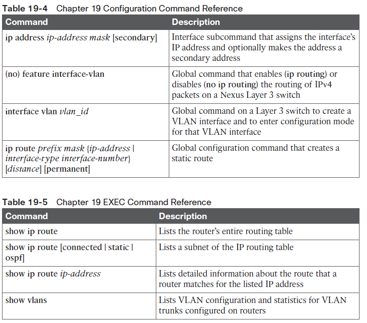
The ability to route IPv4 packets requires the addition of a Layer 3 module with associated licensing, with a reload of the switch required to enable the feature.Step 1. Enable Feature for configuring interface VLANs (feature interface-vlan).Step 2. Create VLAN interfaces for each VLAN for which the Layer 3 switch is routing packets (interface vlan vlan_id).Step 3. Configure an IP address and mask on the VLAN interface (in interface configuration mode for that interface), enabling IPv4 on that VLAN interface (ip address address mask).Step 4. If the switch defaults to place the VLAN interface in a disabled (shutdown) state, enable the interface (no shutdown).
Page 5
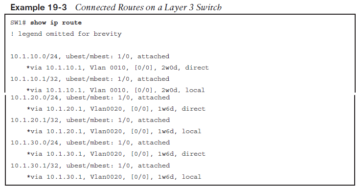
With the VLAN configuration shown here, the switch is ready to route packets between the VLANs, as shown in Figure 19-2. To support the routing of packets, the switch adds connected IP routes, as shown in Example 19-3. Note that each route is listed as being direct to a different VLAN interface.
Page 6
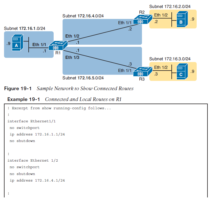
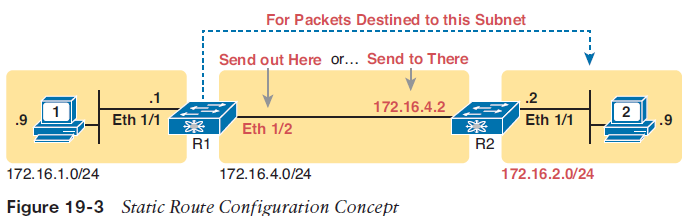
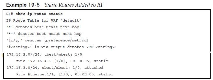
Static Route ConfigurationNX-OS allows the definition of individual static routes using the ip route global configurationcommand. Every ip route command defines a destination that can be matched, usuallywith a subnet ID and mask. The command also lists the forwarding instructions, typicallylisting either the outgoing interface or the next-hop router’s IP address. NX-OS then takesthat information and adds that route to the IP routing table.The figure shows only the details related to a static route on R1, for subnet 172.16.2.0/24, which sits on the far right. To create that static route on R1, R1 will configure the subnet ID and mask, and either R1’s outgoing interface (Ethernet 1/1), or R2 as the next-hop router IP address (172.16.4.2).
Page 7
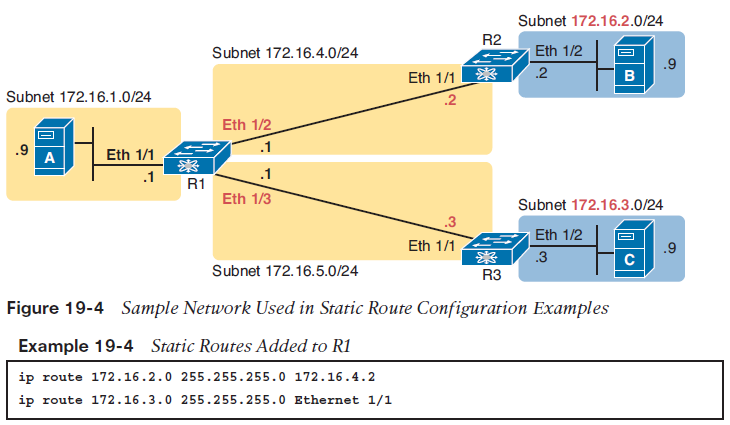
The two example ip route commands show the two different styles. The first command shows subnet 172.16.2.0, mask 255.255.255.0, which sits in the datacenter near Nexus R2. That same first command lists 172.16.4.2, R2’s IP address, as the next-hop router. This route basically says this: To send packets to the subnet off Nexus R2, send them to R2. The second route has the same kind of logic, but instead of identifying the next router by IP address, it lists the local router’s outgoing interface. This route basically states: To send packets to the subnet off router R3, send them out my own local Ethernet 1/1 interface (which happens to connect to R3).
Page 9
NX-OS adds and removes these static routes dynamically over time, based on whether the outgoing interface is working. For example, in this case, if R1’s Ethernet 1/1 interface fails, R1 removes the static route to 172.16.3.0/24 from the IPv4 routing table. Later, when the interface comes up again, NX-OS adds the route back to the routing table.
Page 10
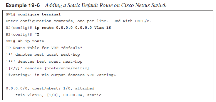
Static Default RoutesWhen a router tries to route a packet, the router might not match the packet’s destination IPaddress with any route. When that happens, the router normally just discards the packet.Routers can be configured so that they use either a statically configured or dynamicallylearned default route. The default route matches all packets, so that if a packet does notmatch any other more specific route in the routing table, the router can at least forward thepacket based on the default route.NX-OS allows the configuration of a static default route by using special values for the subnetand mask fields in the ip route command: 0.0.0.0 and 0.0.0.0. For example, the commandip route 0.0.0.0 0.0.0.0 vlan 16 creates a static default route on Cisco Nexus switch—a routethat matches all IP packets—and sends those packets out SVI VLAN 16.
Want to create your own Notes for free with GoConqr? Learn more.