
Mapa mental
Chapter 5: System modeling (3705)
Conteúdo do mapa
Chapter 5: System modeling (3705)
Context Models
- At an early stage in the specification of a system, you should decide on the system boundaries, that is, on what is and is not part of the system being developed
- Once some decisions on the boundaries of the system have been made, part of the analysis activity is the definition of that context and the dependencies that a system has on its environment
Interaction Models
- All systems involve interaction of some kind. This can be user interaction, which involves user inputs and outputs; interaction between the software being developed and other systems in its environment; or interaction between the components of a software system.
- identify user requirements. Modeling system-to-system interaction
- This section discusses two related approaches to interaction modeling:
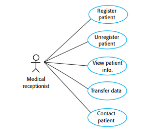
- Use case modeling, which is mostly used to model interactions between a system and external agents (human users or other systems).
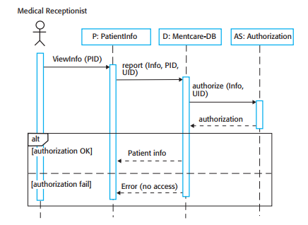
- Sequence diagrams, which are used to model interactions between system components, although external agents may also be included.
- the details of the interactions involved in a high-level use case may be documented in a sequence diagram
- Use case modeling
- Each use case represents a discrete task that involves external interaction with a system
- Sequence diagrams
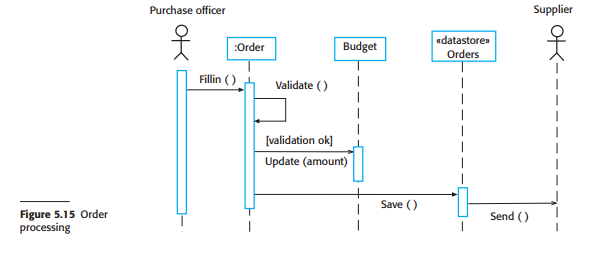
- Sequence diagrams in the UML are primarily used to model the interactions between the actors and the objects in a system and the interactions between the objects themselves
- As the name implies, a sequence diagram shows the sequence of interactions that take place during a particular use case or use case instance
Structural Models
- Structural models of software display the organization of a system in terms of the components that make up that system and their relationships.
- Focus is on the use of class diagrams for modeling the static structure of the object classes in a software system
- static models, which show the organization of the system design
- dynamic models, which show the organization of the system when it is executing.
- Class diagrams
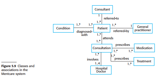
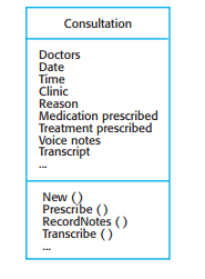
- Class diagrams are used when developing an object-oriented system model to show the classes in a system and the associations between these classes.
- As an implementation is developed, you define implementation objects to represent data that is manipulated by the system.
- Class diagrams in the UML can be expressed at different levels of detail. When you are developing a model, the first stage is usually to look at the world, identify the essential objects, and represent these as classes.
- As you can see from Figure 5.9, other multiplicities are possible.
- At this level of detail, class diagrams look like semantic data models. Semantic data models are used in database design.
- Generalization
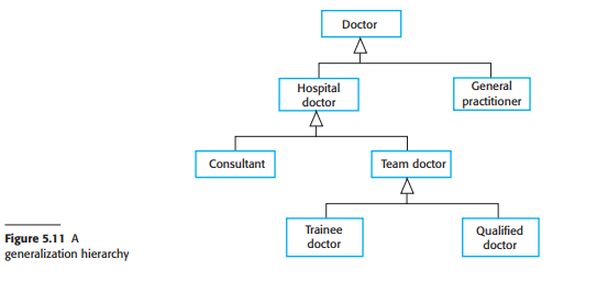
- Generalization is an everyday technique that we use to manage complexity.
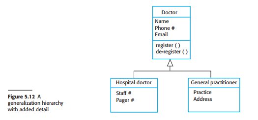
- The lower-level classes are subclasses that inherit the attributes and operations from their superclasses. These lower-level classes then add more specific attributes and operations.
- Aggregation
- Objects in the real world are often made up of different parts.
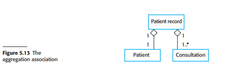
- The UML provides a special type of association between classes called aggregation, which means that one object (the whole) is composed of other objects (the parts).
- Figure 5.13 shows that a patient record is an aggregate of Patient and an indefinite number of Consultations.
Behavioral models
- Behavioral models are models of the dynamic behavior of a system as it is executing.
- what happens or what is supposed to happen when a system responds to a stimulus from its environment.
- These stimuli may be either data or events:
- Data becomes available that has to be processed by the system. The availability of the data triggers the processing.
- An event happens that triggers system processing. Events may have associated data, although this is not always the case.
- These stimuli may be either data or events:
- Many business systems are data-processing systems that are primarily driven by data
- Data-driven modeling
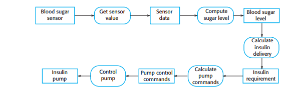
- Data-driven models show the sequence of actions involved in processing input data and generating an associated output.
- used during the analysis of requirements as they show end-to-end processing in a system
- structured design methods used data-flow diagrams (DFDs)
- Data-flow models are useful because tracking and documenting how data associated with a particular process moves through the system help analysts and designers understand what is going on in the process
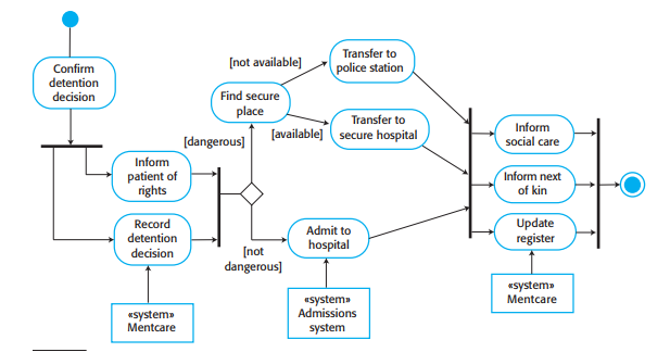
- You can see the processing steps, represented as activities (rounded rectangles), and the data flowing between these steps, represented as objects (rectangles)
- An alternative way of showing the sequence of processing in a system is to use UML sequence diagrams.
- if you draw these so that messages are only sent from left to right, then they show the sequential data processing in the system
- Data-driven modeling
- By contrast, real-time systems are usually event-driven, with limited data processing
- Event-driven modeling
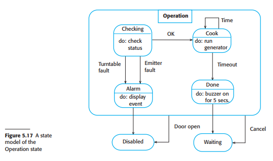
- Event-driven modeling shows how a system responds to external and internal events.
- based on the assumption that a system has a finite number of states and that events (stimuli) may cause a transition from one state to another
- Event-driven modeling is used extensively when designing and documenting real-time systems
- The problem with state-based modeling is that the number of possible states increases rapidly. For large system models, therefore, you need to hide detail in the models. One way to do this is by using the notion of a “superstate” that encapsulates a number of separate states. Example above
- Event-driven modeling
Model-driven engineering
- software development whereby models rather than programs are the principal outputs of the development process
- The programs that execute on a hardware/ software platform are generated automatically from the models
- Model-driven engineering was developed from the idea of model-driven architecture (MDA).
- MDA focuses on the design and implementation stages of software development, whereas MDE is concerned with all aspects of the software engineering process
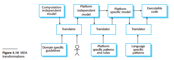
- Model-driven architecture (MDA) is a model-focused approach to software design and implementation that uses a subset of UML models to describe a system.
- The MDA method recommends that three types of abstract system model should be produced:
- A computation independent model (CIM)
- CIMs model the important domain abstractions used in a system and so are sometimes called domain models
- security CIM in which you identify important security abstractions such as an asset
- CIMs model the important domain abstractions used in a system and so are sometimes called domain models
- A platform-independent model (PIM)
- PIMs model the operation of the system without reference to its implementation.
- show the static system structure and how it responds to external and internal events.
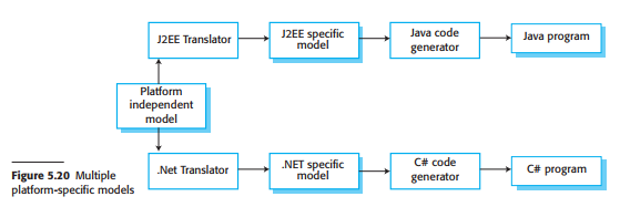
- Platform-specific models (PSM)
- PSMs are transformations of the platformindependent model with a separate PSM for each application platform.
- first level PSM could be middleware-specific but database-independent. When a specific database has been chosen, a databasespecific PSM can then be generated.
- A computation independent model (CIM)
- By using powerful tools, system implementations can be generated for different platforms from the same model.
- to adapt the system to some new platform technology, you write a model translator for that platform
- Fundamental to MDA is the notion that transformations between models can be defined and applied automatically by software tools
- The MDA method recommends that three types of abstract system model should be produced:
- why MDA has not become a mainstream approach to software development
- The translation of high-level CIM to PIM models remains a research problem,
- Although MDA support tools include platform-specific translators, these sometimes only offer partial support for translating PIMS to PSMs
- Companies do not want to develop or maintain their own tools or to rely on small software companies, who may go out of business, for tool development.
- Models are a good way of facilitating discussions about a software design. However, it does not always follow that the abstractions that are useful for discussions are the right abstractions for implementation.
- For most complex systems, implementation is not the major problem— requirements engineering, security and dependability, integration with legacy
- The arguments for platform independence are only valid for large, long-lifetime systems, where the platforms become obsolete during a system’s lifetime
- The widespread adoption of agile methods over the same period
- The success stories for MDA (OMG 2012) have mostly come from companies that are developing systems products, which include both hardware and software. The software in these products has a long lifetime and may have to be modified to reflect changing hardware technologies
System modeling is the process of developing abstract models of a system, with each model presenting a different view or perspective of that system
1. Models are used during the requirements engineering process to help derive the detailed requirements for a system, 2. during the design process to describe the system to engineers implementing the system, and 3. after implementation to document the system’s structure and operation.
develop models of both the existing system and the system to be developed:
- Models of the existing system are used during requirements engineering.
- Models of the new system are used during requirements engineering to help explain the proposed requirements to other system stakeholders.
system model is not a complete representation of system
You may develop different models to represent the system from different perspectives. For example:
- An external perspective, where you model the context or environment of the system.
- An interaction perspective, where you model the interactions between a system and its environment
- A structural perspective, where you model the organization of a system or the structure of the data processed by the system.
- A behavioral perspective, where you model the dynamic behavior of the system and how it responds to events.
There are three ways in which graphical models are commonly used:
- As a way to stimulate and focus discussion about an existing or proposed system.
- Models may be incomplete.
- Cover areas of discussion
- As a way of documenting an existing system
- May be incomplete
- As a detailed system description that can be used to generate a system implementation
- Models must be complete
- As a way to stimulate and focus discussion about an existing or proposed system.
UML modelling diagrams
- Activity diagrams, which show the activities involved in a process or in data processing.
- Use case diagrams, which show the interactions between a system and its environment.
- Sequence diagrams, which show interactions between actors and the system and between system components.
- Class diagrams, which show the object classes in the system and the associations between these classes
- State diagrams, which show how the system reacts to internal and external events.
Imagens e arquivos do mapa
Informações
- Descrição
- Computer Science Mapa Mental sobre Chapter 5: System modeling (3705), criado por Gideon Van em 17-01-2019.
- Criado por
- Gideon Van
- Visualizações
- 0
- Avaliação