
Digital Multimeters (Mod.3 Sect.1 Part 4)
Slides in this set (1)
-
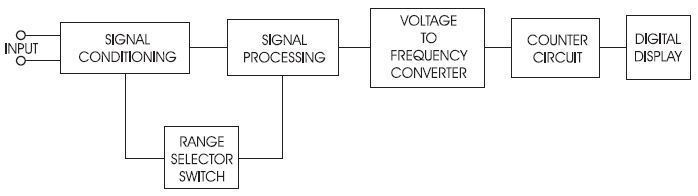
- Caption: Shown here is a simplified block diagram of a digital VOM’s internal circuits.... That's intense -->
- First, note the location of the signal inputs. Incoming signals from the circuit being measured enter the multimeter at the inputs. The signal then transfers to the signal conditioning block, which cleans up any electrical noise or interference from the input signals. Note that the range selector switch is connected to this section of the circuit. The range selector switch is used to connect the proper shunt resistors inside the meter and to select the type of signal conditioning that’s applied to the signal. For example, an incoming AC signal will be rectified (changed to DC) in this circuit.
- Next, the signal is applied to a signal processing circuit. Depending upon the position of the range switch, different types of signal processing will take place. The output of this circuit is an analog DC voltage that will be applied to the next circuit block.
- The next circuit block contains a voltage-to-frequency converter. This block converts the conditioned and processed analog voltage to a frequency. If the incoming voltage is low, the output frequency will be low. If the voltage from the processing section is high, the output frequency of this circuit will be high.
- The frequency output of this stage is then passed on to a counter circuit. This circuit counts the pulses of the output of the voltage-to-frequency converter (over a very short period of time). In the final stage of the process, the counted value is passed on to the digital display and is displayed on the front panel of the digital meter.
Information
- Description
- Even more multimeter stuff. Whoop.
- Created by
- That Yeti Dog Person
- Views
- 0
- Tags
- Rating