
Flowchart
PhotoMOS
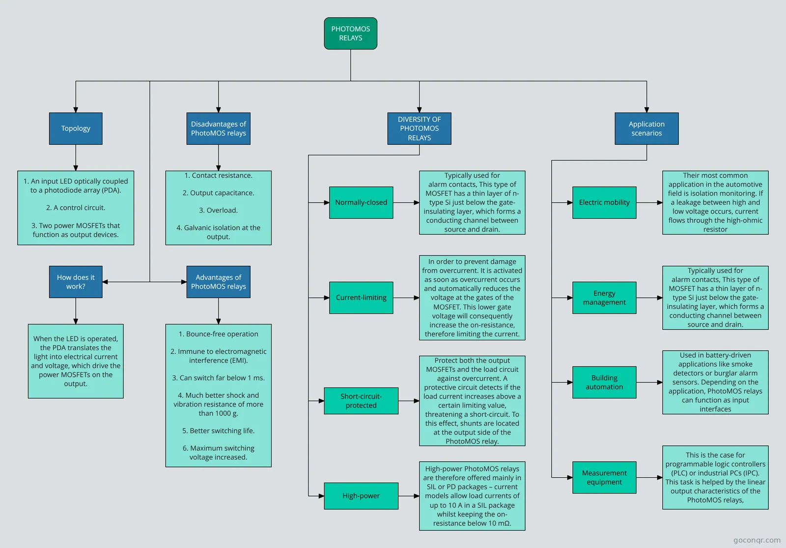
Flowchart: PhotoMOS relays
Flowchart content
Topology
How does it work?
When the LED is operated, the PDA translates the
light into electrical current and voltage, which drive the power MOSFETs on the output.
Advantages of PhotoMOS relays
1. Bounce-free operation
2. Immune to electromagnetic interference (EMI).
3. Can switch far below 1 ms.
4. Much better shock and vibration resistance of more than 1000 g.
5. Better switching life.
6. Maximum switching voltage increased.
Disadvantages of PhotoMOS relays
1. Contact resistance.
2. Output capacitance.
3. Overload.
4. Galvanic isolation at the
output.
PHOTOMOS
RELAYS
DIVERSITY OF PHOTOMOS RELAYS
Typically used for
alarm contacts, This type of MOSFET has a thin layer of n-type Si just below the gate-insulating layer, which forms a conducting channel between source and drain.
Normally-closed
In order to prevent damage from overcurrent. It is activated
as soon as overcurrent occurs and automatically reduces the voltage at the gates of the MOSFET. This lower gate voltage will consequently increase the on-resistance, therefore limiting the current.
Current-limiting
Protect both the output MOSFETs and the load circuit against overcurrent. A protective circuit detects if the load current increases above a
certain limiting value, threatening a short-circuit. To this effect, shunts are located at the output side of the PhotoMOS relay.
Short-circuit-protected
High-power PhotoMOS relays
are therefore offered mainly in SIL or PD packages – current
models allow load currents of up to 10 A in a SIL package whilst keeping the on-resistance below 10 mΩ.
High-power
Application scenarios
Their most common application in the automotive
field is isolation monitoring. If a leakage between high and low voltage occurs, current flows through the high-ohmic resistor
shunts, leading to a voltage drop.
Electric mobility
Typically used for
alarm contacts, This type of MOSFET has a thin layer of n-type Si just below the gate-insulating layer, which forms a conducting channel between source and drain.
Energy management
Used in battery-driven applications like smoke
detectors or burglar alarm sensors. Depending on the application, PhotoMOS relays can function as input interfaces
for system sensors and output interfaces for alarm contacts.
Building automation
This is the case for programmable logic controllers
(PLC) or industrial PCs (IPC). This task is helped by the linear
output characteristics of the PhotoMOS relays,
Measurement equipment
1. An input LED optically coupled to a photodiode array (PDA).
2. A control circuit.
3. Two power MOSFETs that function as output devices.
Information
- Description
- Flowchart on PhotoMOS, created by Daniel Barrera Martinez on 11/03/2022.
- Created by
- Daniel Barrera Martinez
- Views
- 3
- Rating