
Flashcards
cs 2212
Cards in this deck (119)
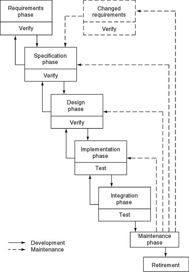
- 1Define Software Life-Cycle Models: Life-cycle model (also, process model)The software development and operation activities and their ordering, like
* Requirements elicitation
* Specification
* Design
* Implementation
* Integration
* Maintenance phase
* Retirement - 2How is waterfall model characterized?* Sequential steps (phases)
* Feedback loops (between two phases in development)
* Documentation-driven - 3Advantages of waterfall model* Documentation
* Maintenance easier - 4Disadvantages of waterfall model* Complete and frozen specification document up-front often not feasible in practice
* Customer involvement in the first phase only
* Sequential and complete execution of phases often not desirable
* Process difficult to control
* The product becomes available very late in the process - 5What is incremental model?* Each release adds more functionality, i.e., a new increment
* (Some call it iterative)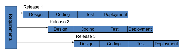
- 6What are the advantages of incremental model?* Generates working software quickly and early during the software life cycle.
* This model is more flexible – less costly to change scope and requirements.
* It is easier to test and debug during a smaller iteration.
* In this model customer can respond to each built.
* Lowers initial delivery cost.
* Easier to manage risk because risky pieces are identified and handled during it’d iteration. - 7What are the disadvantages of incremental model* Needs good planning and design.
* Needs a clear and complete definition of the whole system before it can be broken down and built incrementally.
* Total cost is higher than waterfall. - 8what is evolutionary model?* Evolutionary models are iterative type models.
* They allow to develop more complete versions of the software.
* Following are the evolutionary process models.
1. The prototyping model
2. The spiral model
3. Concurrent development model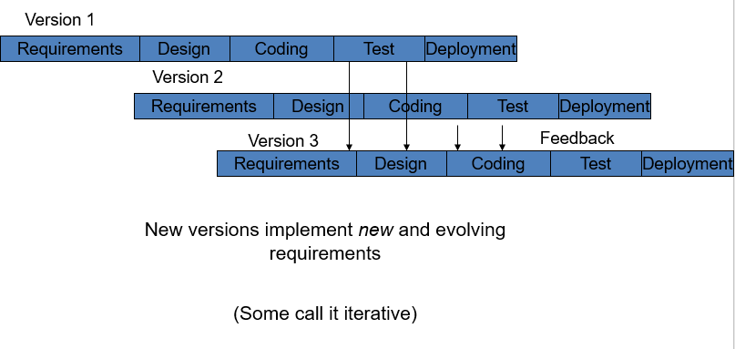
- 9What is a spiral model?* Spiral model is a risk driven process model.
* It is used for generating the software projects.
* In spiral model, an alternate solution is provided if the risk is found in the risk analysis, then alternate solutions are suggested and implemented.
* It is a combination of prototype and or waterfall model.
* In one iteration all activities are done, for large project's the output is small.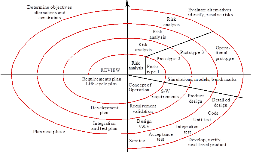
- 10What are the advantages of spiral model?* Spiral model is a risk driven process model.
* It is used for generating the software projects.
* In spiral model, an alternate solution is provided if the risk is found in the risk analysis, then alternate solutions are suggested and implemented.
* It is a combination of prototype and sequential model or waterfall model.
* In one iteration all activities are done, for large project's the output is small. - 11What are the disadvantages of spiral model?* It can be costly to develop a software model.
* It is not used for small projects. - 12What are the four main variables of a project?The main four variables of a project
* Development cost
* Time
* Quality
* Scope - 13why are Development cost, time and quality bad control variables?* The number of developers can only be incrementally increased (negative effects beyond the optimal count)
* Deadlines are often predetermined externally (e.g., market window, important presentation)
* Low quality upsets customers and developers
* Scope is the only real control variable - 14What is a COCOMO Model?* Cocomo (Constructive Cost Model) is a regression model based on LOC, i.e number of Lines of Code.
* It is a procedural cost estimate model for software projects and often used as a process of reliably predicting the various parameters associated with making a project such as size, effort, cost, time and quality. - 15Different characteristics of projects pertain to different system types. What are the three different types of systems?* Organic
* Semidetached
* Embedded
All the above system types utilize different values of the constants used in Effort Calculations.
*KDSI = Kilo Delivered Source Instructions - 16What is an Organic system? Organic mode formula: PM = 2.4 (KDSI) 1.05A software project is said to be an organic type
* if the team size required is adequately small,
*the problem is well understood and has been solved in the past.
* And also the team members have a nominal experience regarding the problem - 17What is a semidetached system? Semi-detached mode: PM = 3 (KDSI) 1.12A software project is said to be a Semi-detached type
* if the vital characteristics such as team-size, experience, knowledge of the various programming environment lie in between that of organic and Embedded.
* The projects classified as Semi-Detached are comparatively less familiar and difficult to develop compared to the organic ones.
* require more experience and better guidance and creativity. - 18What is an embedded System? Embedded mode: PM = 3.6 (KDSI) 1.2* A software project with requiring the highest level of complexity, creativity, and experience requirement fall under this category.
* Such software requires a larger team size than the other two models.
* Also the developers need to be sufficiently experienced and creative to develop such complex models. - 19abbreviations of calculation resultsPM = Person-Months (is a measure of effort).
- 20COCOMO EXAMPLE...Organic mode project, 32KLOC
* PM = 2.4 (32) 1.05 = 91 person months
* TDEV = 2.5 (91) 0.38 = 14 months
* N = 91/15 = 6.5 people
Embedded mode project, 128KLOC
* PM = 3.6 (128)1.2 = 1216 person-months
* TDEV = 2.5 (1216)0.32 = 24 months
* N = 1216/24 = 51 - 21Cohesion: is a property of one component or a classDenotes “The measure of the strength of functional relatedness of elements within a module”
* High cohesion: The classes in a component (or the methods in a class) offer related to each other functionality. They are also related, using associations
* Low cohesion: The classes in a component (or the methods in a class) offer functionality that are not related between them. Also these classes are not related using associations - 22Coupling: is a measure of dependency between two or more subsystemsDenotes “The degree of interdependence between software modules; a measure of how closely connected two routines or modules are”
* High coupling: Changes in one subsystem or component cause changes or affect the function of the other subsystems
* Low coupling: Changes in one subsystem or component cause changes or affect the function of the other subsystems - 23what characteristics should system exhibit?A system has to exhibit high cohesion with respect to each of its components and low coupling between its associated components
- 24Types of cohesion
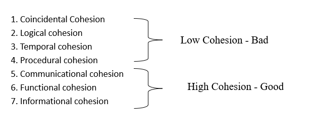
- 25Co-incidental cohesion* It is unplanned and random cohesion, which might be the result of breaking the program into smaller modules for the sake of modularization.
* Because it is unplanned, it may serve confusion to the programmers and is generally not-accepted. - 26Logical cohesion* When logically categorized elements are put together into a module, it is called logical cohesion.
- 27Temporal Cohesion* When elements of module are organized such that they are processed at a similar point in time, it is called temporal cohesion.
- 28Procedural cohesion* When elements of module are grouped together, which are executed sequentially in order to perform a task, it is called procedural cohesion.
- 29Communicational cohesionWhen elements of module are grouped together, which are executed sequentially and work on same data (information), it is called communicational cohesion.
- 30Sequential cohesionWhen elements of module are grouped because the output of one element serves as input to another and so on, it is called sequential cohesion.
- 31Level of coupling...
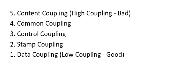
- 32Content couplingWhen a module can directly access or modify or refer to the content of another module, it is called content level coupling.
- 33Common couplingWhen multiple modules have read and write access to some global data, it is called common or global coupling
- 34Control couplingTwo modules are called control-coupled if one of them decides the function of the other module or changes its flow of execution.
- 35Stamp couplingWhen multiple modules share common data structure and work on different part of it, it is called stamp coupling.
- 36Data couplingData coupling is when two modules interact with each other by means of passing data (as parameter). If a module passes data structure as parameter, then the receiving module should use all its components.
- 37What is domain model?The model that describes the “things” is referred to as the domain model
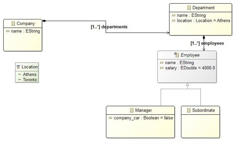
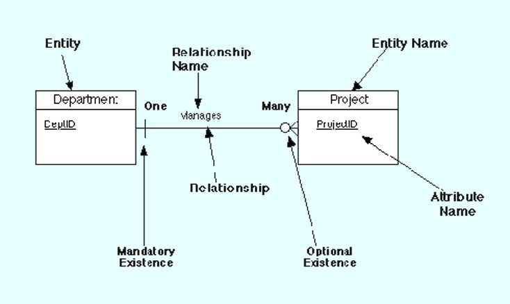
- 38Entity-Relationship Diagram* E-R diagrams denote entities (usually data) and the relationship between them
* There are different E-R diagram notations but the concept is the same - 39Structural Elements of E-R DiagramsEntities: Τhe prototypes of the system entities being modeled (e.g. traveler, airline reservation, departure time etc.).
Attributes: Characteristics of the entities (e.g. traveler name, airline reservation ID)
* Atomic
* Compound
* Multi-valued
* Derived
* Key
Relationships:
Relationships between two or more entities (e.g. airline reservation relates to a traveler and a departure time)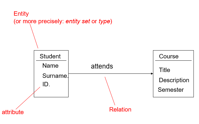
- 40E-R Diagram example
- 41Structural Elements of Use Case Diagrams (1)
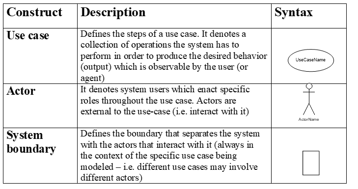
- 42Association

- 43Generalization

- 44<>

- 45<>

- 46Tips for Use Case ModelsNouns = Entities/Actors
Verbs = the operations in the scenario. - 47Use Case Model consists of...Use Case Model = Use Case Diagram + Use Case Description.
* We have one use case model for each functional requirement presented by the user - 48Functional Requirements Specification consists of...Functional Requirements Specification = Use Case Models (one for each use case) + Sequence Diagrams (one for each Use Case) + Communication Diagrams (one for each use case) + Supporting material
- 49Requirements Specifications consists of...Requirements Specifications = Functional Requirements Specification + Non-functional Requirements Specification + Supporting material
- 50UML Interaction DiagramsUML Interaction Diagrams include:
Sequence Diagrams
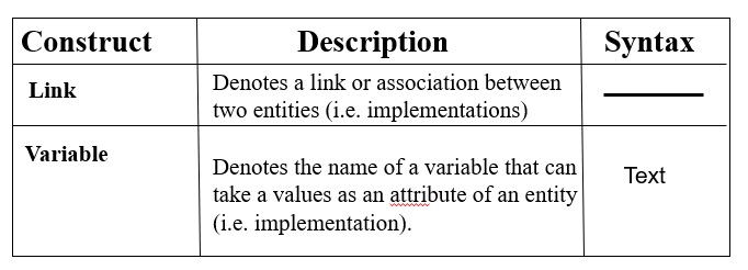
Collaboration Diagrams: In UML 2.0 the Collaboration Diagrams are referred to as Communication Diagrams - 51Structural Elements of Interaction Diagrams (1)
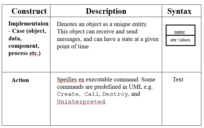
- 52Structural Elements of Interaction Diagrams (2)
- 53Structural Elements of Interaction Diagrams (3)
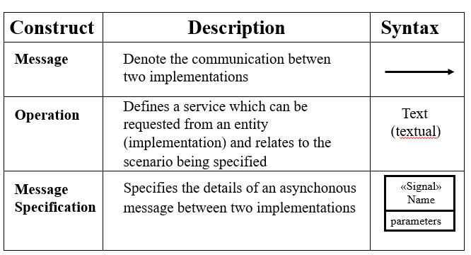
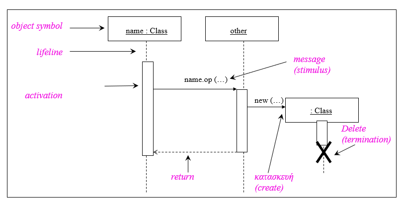
- 54Structure of a Sequence Diagram
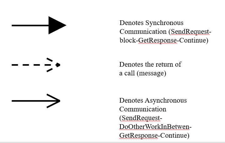
- 55Message Types
- 56why do we use sequence diagram?* To model how messages associate over time
* To model real time systems - 57Use of Activity DiagramsActivity diagrams are useful on modeling process steps in applications where processes depend on the exchange of data or entail complex flow of logic
- 58Terminology for Activity Diagrams
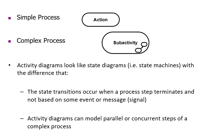
- 59Simple Process (State)
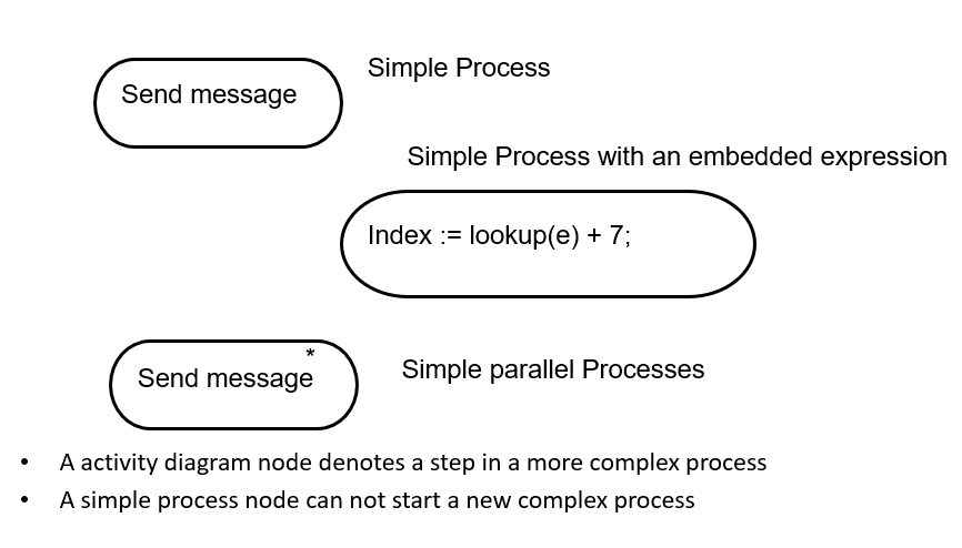
- 60Complex Process
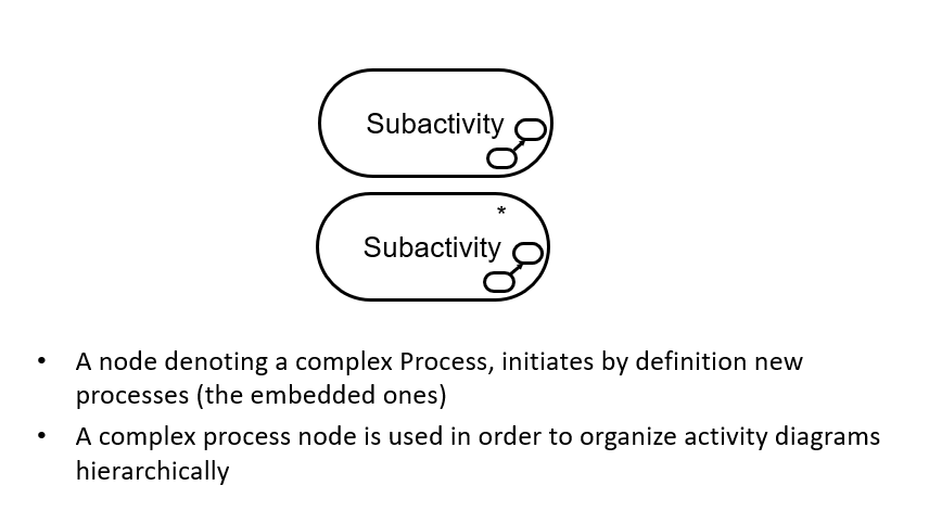
- 61Activity Model Example
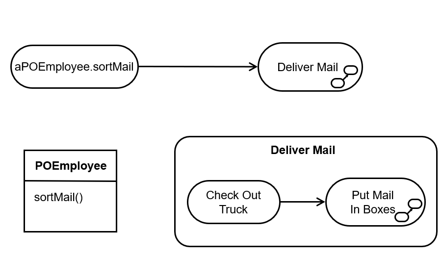
- 62Final and initial Nodes
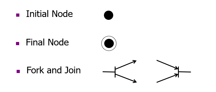
- 63Decision Points
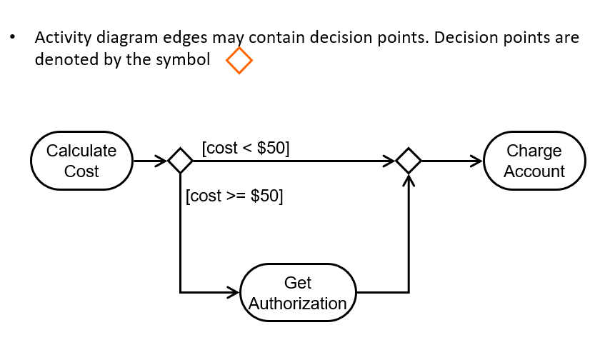
- 64Parallel Processes – Synchronization Points
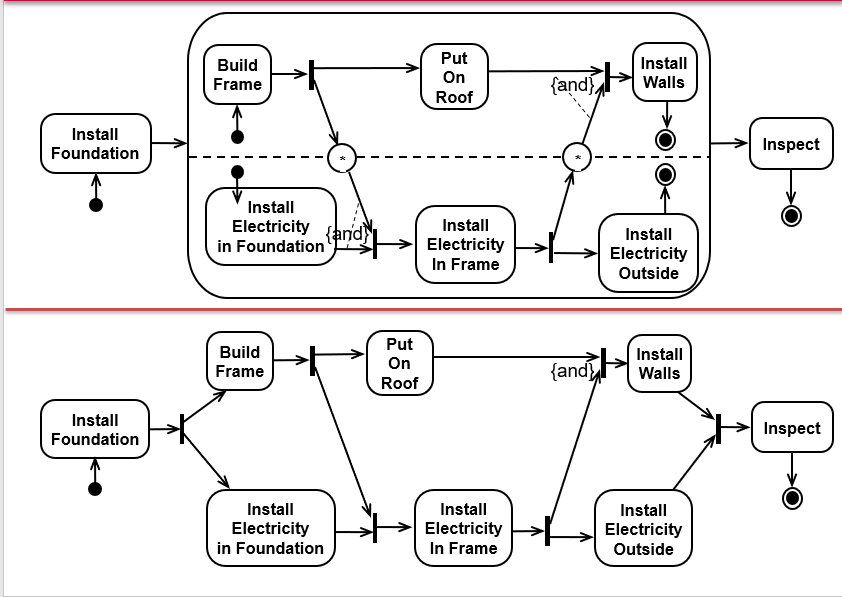
- 65Signals* Signal receipt is a natural way to model a wait state.
* Dashed line notation is specifically for use with the signal icons.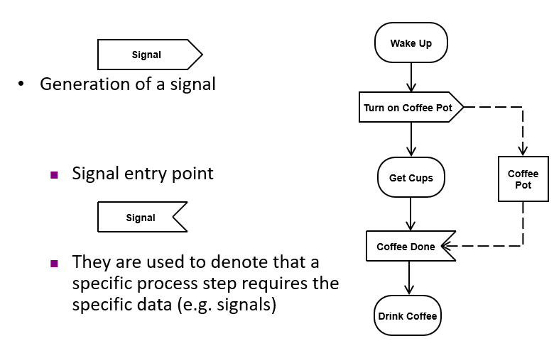
- 66Activity Diagram Example
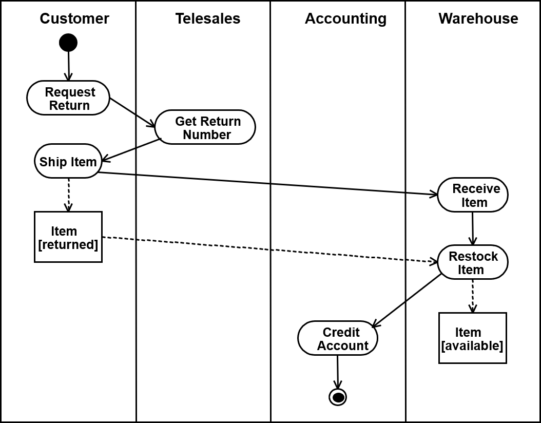
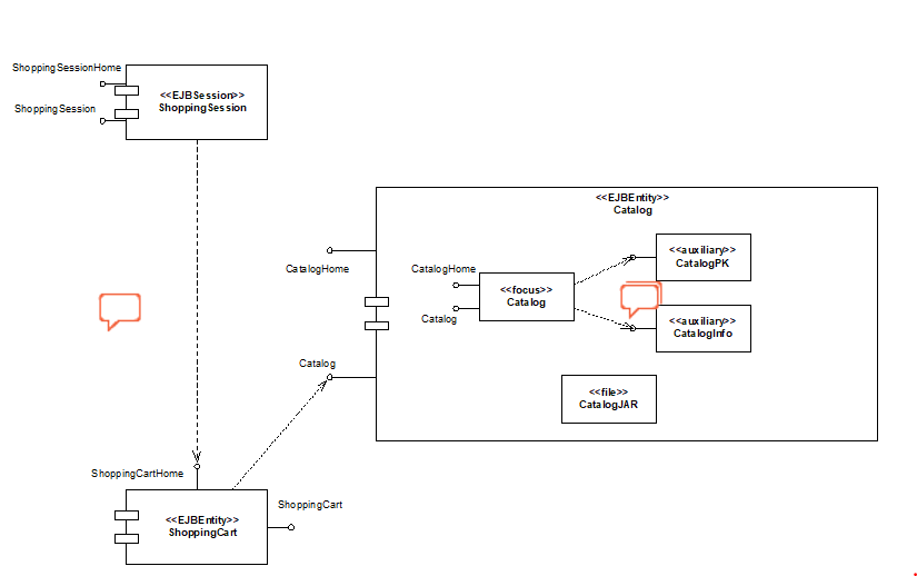
- 67Component DiagramsThese diagrams model the structure of the system as a collection of components which interact using specific interfaces and exchange messages through these interfaces
* A good design has components with high cohesion and low coupling - 68Component diagram example
- 69A system’s architecture is composed ofComponents: package and implement the system’s functions
Connectors: implement the interconnections between the Components - 70An architectural style defines a family of architectures which have:* Common topologies (how components are interconnected)
* Semantic constraints
* Common vocabulary for their components and their connectors - 71Data Flow Style: A data flow system is one in which:* The availability of data controls the computation
* The structure of the design is determined by the orderly motion of data from component to component
* The pattern of data flow is explicit
* This is the only form of communication between components - 72Kinds of Data Flow Architectures* Batch sequential
* Dataflow network (pipes&filters)
acyclic, fanout, pipeline, Unix, etc.
* Closed loop control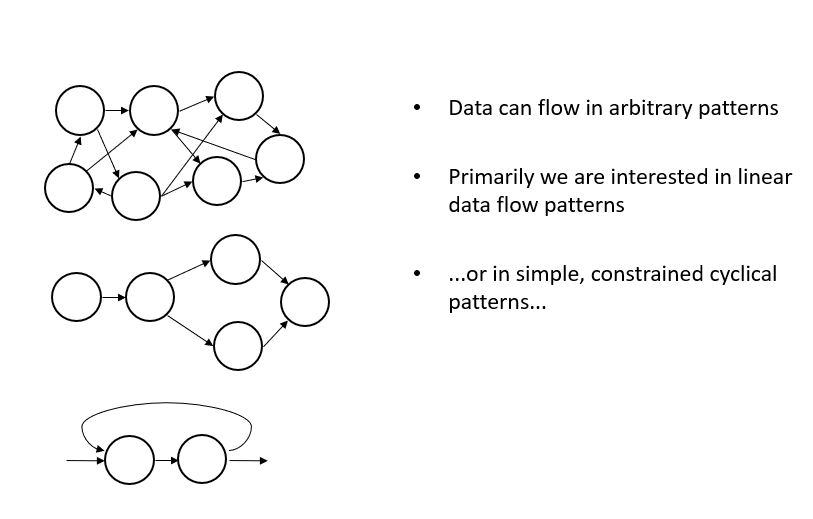
- 73What Is Software Reliability?* Defn.: Probability(failure-free op, specified time, given environment) -> P(t)
* Affected by development process—not ageing/ manufacturing - 74Basic concepts of software reliability?* Failure and fault
* Time
* Characterizing failure occurrence in time - 75Failure and fault* Failure: departure of external results of program operation
* Fault: cause of failure (localized or not) - 76Time* Execution time (t)
* Calendar time (t): meaningful to managers - 77Characterizing failure occurrence in time* Time of failure: instant
* Time interval between failures
* Cumulative failures up to a given time
* Failures in a time interval - 78Transformational data analysisRaw data is gathered and analyzed in a step-wise, batch-oriented fashion. eg:
Payroll computations
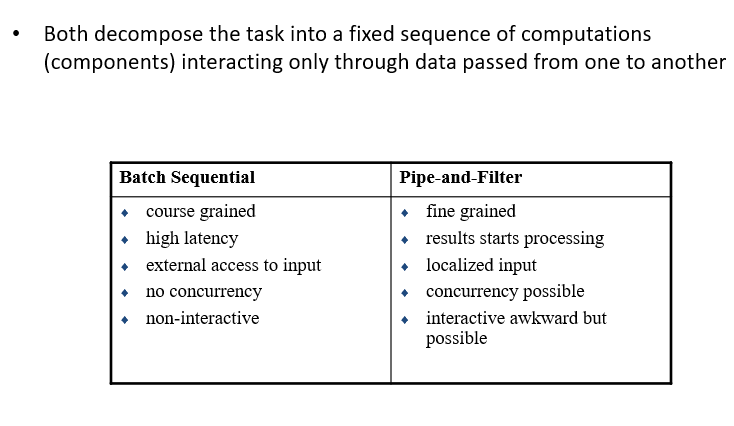
CRA tax return computations - 79Pipes and Filtersdata in the pipe&filter style is processed incrementally-
The Pipes and Filters architectural pattern [style] provides a structure for systems that process a stream of data. Each processing step is encapsulated in a filter component. Data is passed through pipes between adjacent filters. Recombining filters allows you to build families of related systems.” - 80Pipe-and-Filter vs. Batch Sequential
- 81List of design goalsReliability - Good documentation
Modifiability - Well-defined interfaces
Maintainability - User-friendliness
Understandability - Reuse of components
Adaptability - Rapid development - 82software required specification software design- What to do
_ How to do it - 83Levels of Software Design*Architectural design (or high-level design)
* Detailed design (or low-level design) - 84Architectural design (or high-level design)* Architecture – Focuses in the general structure of the system (subsystems, components) and the relationships between them
* It aims to cover the implementation of all use cases
* It aims to cover the implementation of all non-functional requirements
* It does not change quite a lot over time - 85Detailed design (or low-level design)* Denotes the design of the internal structure of each component / class
* It takes into account the programming language to be used
* The design specification is detailed enough so that it can readily implemented in an appropriate programming language - 86Good Properties of an Architecture* Result of a consistent set of principles and techniques, applied consistently through all phases of a project
* Resilient in the face of (inevitable) changes
* Source of guidance throughout the product lifetime
* Reuse of established engineering knowledge - 87Issues Addressed by an Architectural Design* Gross decomposition of a system into interacting components
* Emergent system properties
* Rationale - Relates requirements and implementations
* Envelope of allowed change - 88Characteristics of Batch Sequential Systems* Components are independent
* Each step runs to completion before the next step begins
* The flow of data carries a batch of data as a whole from one subsystem to another.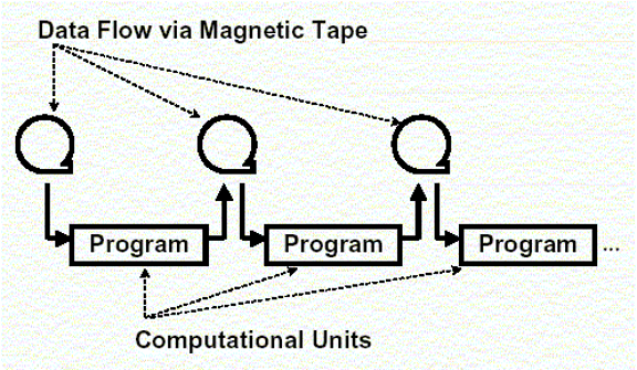
- 89Main & subroutine/ call & return* a software system is divided into subroutines by using top-down refinement according to desired functionality of the system.
* These refinements lead vertically until the decomposed modules is simple enough to have its exclusive independent responsibility.
* Functionality may be reused and shared by multiple callers in the upper layers.
* values passed as data or reference - 90Event driven architectural style* An event-driven architecture consists of event producers that generate a stream of events, and event consumers that listen for the events
* a producer doesn't know which consumers are listening.
* Consumers are also decoupled from each other, and every consumer sees all of the events. - 91Model-View-ControllerA decomposition of an interactive system into three components:
A model containing the core functionality and data,
One or more views displaying information to the user, and
One or more controllers that handle user input. - 92Repositories / Data Centred* A repository architecture consists of a central data structure
(often a database) and a collection of independent components which operate on the central data structure
Connections between data store and external components vary considerably in this style:
* Transactional databases: Incoming stream of transactions trigger processes to act on data store. Passive.
* Blackboard architecture: Current state of data store triggers processes. Active. - 93Where to use Blackboard ArchitecturesProblems for which no deterministic solution strategy is known, but many different approaches (often alternative ones) exist and are used to build a partial or approximate solution.
- 94Layered Systems“A layered system is organised hierarchically, each layer providing service to the layer above it and serving as a client to the layer below.” (Garlan and Shaw)
*In a pure layered system: Layers are hidden to all except adjacent layers. - 95Layered Systems example
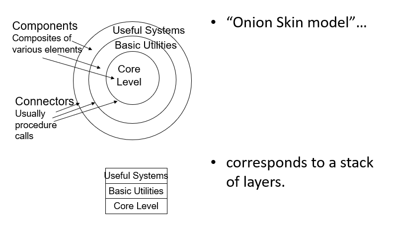
- 96Layered Systems - Interpreter* Architecture is based on a virtual machine produced in software.
* Special kind of a layered architecture where a layer is implemented as a true language interpreter.
* Components are ‘program’ being executed, its data, the interpretation engine and its state. - 97One Tier Client Server Architecture Design
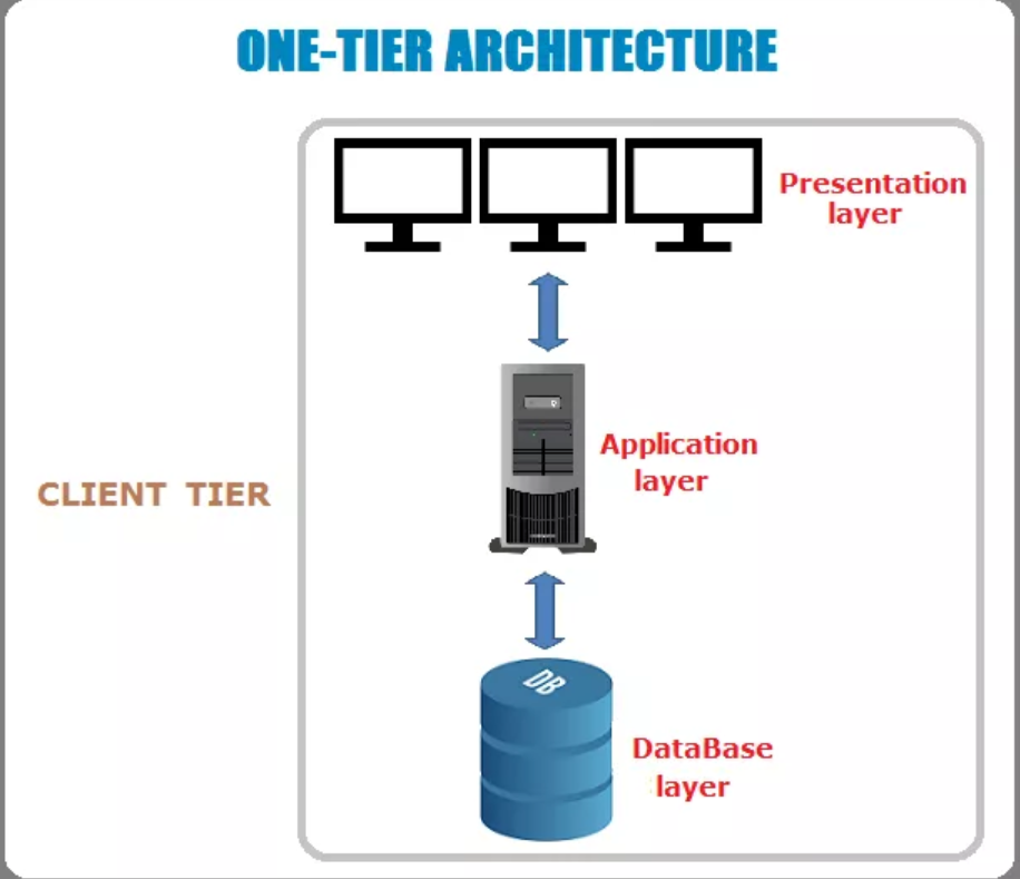
- 98Two Tier Client Server Architecture Design
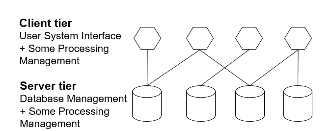
- 99Three Tier Client Server Architecture Design
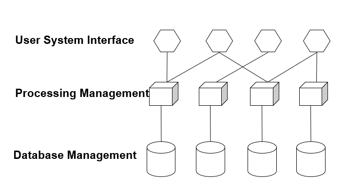
- 100Classification of GoF Design Pattern
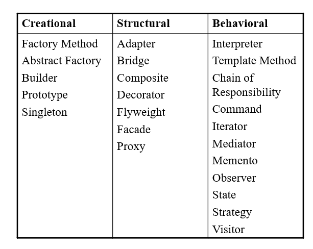
- 101Visitor design pattern* represents an operation to be performed on the elements an object structure. visitors lets you define a new operation without changing the classes of the elements on which it operates.
- 102Iterator (Behavioral)Access the elements of a collection object in sequential manner without any need to know its underlying representation.
- 103Observer (Behavioral)Define a one-to-many dependency between objects so that when one object changes state, all its dependents are notified and updated automatically
- 104State design PatternIt allows for an object of a class to change its behavior according to the state it is. This behavior is applied to all such objects which are in the same state. From an outside client it looks like the object has changed class!
- 105Strategy Design Pattern* you have a family of algorithms, each algorithm has a common interface, but a unique implementation.
You want an elegant solution to make the algorithms interchangeable. - 106Template Method Design Patternyou have group of algorithms that you need to use in the architecture of your application. all algorithms share the same sequence of discrete steps, and they differ only how they implement specific step. you want to use an algorithm in clients code but you want to interchangeably chose a different implementation before breaking the clients ode. it allows you to define the overall structure of the algorithm in a base-case template class. and overwrite specific steps in derived classes.
- 107examples of Template Method Design Pattern. * it calls steps in sequence
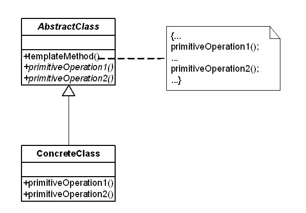
- 108Design Pattern Chain of Responsibilityif your application generates stream of requests that must be handled by the receiver object. However, the problem is that there is no clear one-on-one mapping between the sender and the receiver. perhaps the request receivers are configured at the run time. So then, each receiver examines the request, handles it if applicable, and if not hands the request off to the next receivers in the list.
- 109Adapter Design Patternthe main issue is that you have two objects, with incompatible interfaces with your application that you want to introduce. it acts a wrapper to connect both object's interface to work together
- 110Bridge Design Patternwhen you strictly want to separate interface hierarchy from its implementation hierarchy.
- 111Composite Design Patternit is used when you are creating structure of components that can contain child component.
it is used so that each client uses the component the same way regardless if its a leaf component or composite object.
when you want to compose objects out of one or more child objects. - 112Façade Design PatternAll those classes having complex relations is pretty irrelevant to facade pattern. The only thing important is that those classes are multiple and that the client has to deal with all of them. so the facade class combines interfaces of all needed classes into one interface.
- 113Proxy Design Pattern*Proxy provides a surrogate or placeholder for another object.
proxy is nothing more than a stand in for an object. clients do not call an underlined objects, instead they call the proxy. and the proxy forwards those call to the underlined objects. - 114Decorator Design PatternAdd new features to the methods of a single object
*Decorator design pattern is also known as Wrapper. The structure of this pattern is based on the use of an object (Decorator) that has the same interfaces with the object for which we want to expand its functions. When we call a Decorator method, this call is forwarded to the object that Decorator “wraps". In the process of this call, the Decorator method can add new functionality which is applied either before or after calling the archetypal method of the “wrapped" object. - 115singleton design patternwhen you create a single instance of a class. provide global access to that single access. singleton is instantiated just prior to its use, not at the start of the program.
- 116Factory method design patternWhen constructing objects from classes, we use the “constructor" of the corresponding class. However, there are cases where we do not want the client code to know what kind of objects will be built.
The design pattern is designed to allow us to define an interface, in a class that can be used to construct objects
Essentially, the pattern leaves sub-classes of the Creator class to decide what objects will eventually be made
The factory method pattern, you want to define an interface for creating objects, but you want to let subclasses decided which class to instantiate.
You want to decoupled requesting objects from creating objects.
Calling code doesn't need to know what types of objects are called. - 117Abstract factory patternwhen you want to provide an interface for creating families of related or dependent objects without specifying concrete classes.
Calling code works with abstract interfaces and classes and does not need to know the exact types of objects created by the factory
the factory object provide a creation service for entire collections of platform. - 118software reliabilityit is the probability of failure free software operation for a specified period of time in a specified environment.
- 119AvailabilityAvailability is defined as the probability that the system will behave according to its specifications when it is requested to operate at a certain point in time.
Information
- Description
- - Computer science 2212 Flashcards on cs 2212, created by maah asgharali on 14/04/2019.
- Created by
- maah asgharali
- Views
- 0
- Rating