20038273
Description
Flashcards by AsimAli Rehman , updated more than 1 year ago
|
|
Created by AsimAli Rehman
about 6 years ago
|
|
| Question | Answer |
| Mechanical systems | A |
| What is a linkage and when does it do? | • A linkage is a system of rods connected via pivots • It is used to change the size of a force, and direction of motion |
| Draw a reverse motion linkage and describe how it works. | • This type of linkage has one fixed pivot and two moving pivots • As the top link moves to the right, the bottom link moves to the left, and the motion is thus reversed • If the fixed pivot is equidistant from the moving pivots then the output force is equal to the input force • The output force can be increased or decreased by changing the position of the fixed pivot |
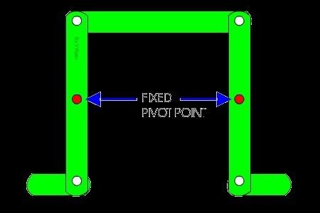
| Draw a parallel motion linkage and describe how it works. |
• This type of linkage has parallel connecting links
• There are two fixed pivots – the rest are moving pivots
• The input and output motion is in the same direction
• The input and output force are the same
Image:
S (binary/octet-stream)
|
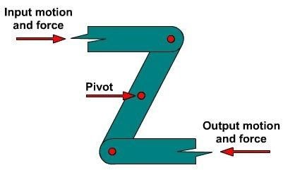
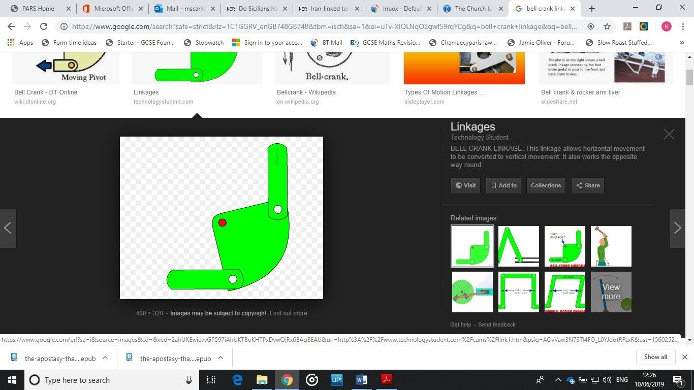
| Draw a bell crank linkage and describe how it works. | • This linkage has one fixed pivot (coloured red in the example above) and two moving pivots • The output motion is at 900 to the input motion • In other words, the bell crank changes horizontal motion to vertical motion, or vice versa • When the fixed pivot is closer to the output lever, the output force is greater than the input force |
| Define mechanical advantage | • Mechanical advantage is a ratio that indicates how much easier or harder it is for a mechanism to carry out an action • It is an indicator of the ability of a mechanism to move a large load with a small effort force • It is calculated using the following formula: Mechanical advantage, MA = load/effort • Load is the output force, and effort is the input force |
| What are the four main types of motion? | • Linear • Rotary • Reciprocating • Oscillating |
| Using examples, define linear motion. | • Linear motion is motion in a straight line, e.g. a train moving along a straight track, or a product moving along a conveyor belt |
| Using examples, define rotary motion. | • Rotary motion is motion that follows the path of a circle, e.g. a wheel turning on a car, a roundabout, or a gear turning on a shaft |
| Using examples, define reciprocating motion. | • Reciprocating motion is motion that goes back and forth (or up and down) in a straight line, e.g. a person jumping up and down on a pogo stick, or a piston cylinder in a car engine |
| Using examples, define oscillating motion. | • Oscillating motion is motion that goes back and forth along a circular path, e.g. a pendulum, a swing, or a door on a hinge |
| Use notes describe the function of a rack and pinion | • A rack and pinion changes rotary motion to linear motion • The rack is a straight bar-shaped gear with teeth • The teeth on the circular pinion mesh with those on the rack • As the pinion turns the system produces one of two possible outcomes: o either the rack will move in a straight line, o or the pinion itself will experience linear motion • An example of a rack and pinion is in the turning handle of a pillar drill, allowing the drill chuck to be both lowered and raised. |
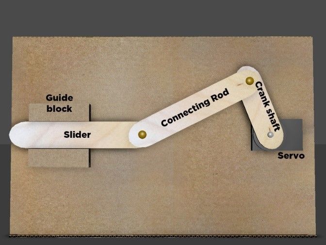
| Use notes and diagram to describe the function of a crank and slider. | • A crank and slider converts rotary motion to reciprocating motion, or vice versa • For rotary to reciprocating, the crank rotates, causing the connecting rod to push the slider back and forth • For reciprocating to rotary, the slider is made to move back and forth, causing the connecting rod to turn the crank and cause rotary motion, e.g. piston engines in road vehicles. |
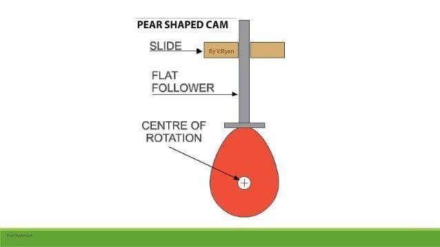
| Use notes and diagrams to describe the function of a cam and follower | • Cams and followers turn rotary motion into reciprocating motion • The follower moves up and down as the cam rotates • The cam can be turned manually using a handle or automatically using a motor |
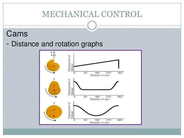
| Explain what is meant by the dwell of a follower |
• The pattern of movement of a cam and follower is determined by the shape of the cam
• The cam shape can make the follower rise, fall, or remain stationary
• When the follower is stationary it is in the dwell portion of the turning cycle
Image:
Dwell (binary/octet-stream)
|
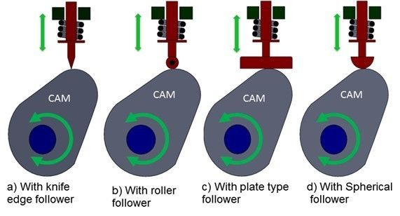
| What types of follower are there? |
• Knife edge – very accurate; can cause wear so rarely used
• Roller – very accurate, roller helps reduce wear
• Flat – can produce stresses, but very useful where space is limited, e.g. in a car engine
• Spherical – reduces stresses as found with flat faced follower
Image:
Cams (binary/octet-stream)
|
| What is the purpose of a simple gear train? | • Gear trains transmit rotary motion using torque (turning forces) • They are made up from two or more spur gears that mesh together • A spur gear is a circular gear with straight teeth • One of gears is the input gear, called the driver • The gear is the output gear, called the driven |
| What affects the size of the output speed from a gear train? | • The output speed from a gear train is affected by: o the diameter (or radius) of the gears o the number of teeth on the gears o the input speed • The relationship between the input speed and the output speed of a gear train is called the gear ratio • Gear ratio = Input speed / Output speed = Driver speed / Driven speed |
| How else can you calculate gear ratio? | • The gear ratio (sometimes called velocity ratio) of a simple gear train can be calculated a number of ways, as follows: • Gear ratio = (Diameter of driven) / (Diameter of driver) • Gear ratio = (Number of teeth on driven gear) / (Number of teeth on driver gear) • Gear ratio = Ndriven / Ndriver |
| Identify and compare an alternative to a gear train | • An alternative method to transfer rotary motion is a chain and sprocket • A series of links are joined together with steel pins to form a chain • The chain fits over the sprockets which are set a distance apart • The driven sprocket moves in the same direction as the driver sprocket • It has fewer parts than a complex gear train, thus saving on cost • However, the chain can jump out of place, or even break if not maintained properly |
| Identify and compare alternative system to a chain and sprocket | • An alternative system to transfer rotary motion is a pulley and pulley belt system • The pulleys are wheels that are set a certain distance apart • The pulley belt can be flat, toothed, or v-groove • An advantage is that pulley systems are cheaper and require less parts than gear train or chain systems • They are also quieter • However, pulley systems cannot transmit as large a torque as chains or gears because the belt can slip • Unlike with gears and chains, if the belt breaks it is not too much of a problem to replace it and it doesn’t cause any real damage to the system |
| Describe how pulley systems can be used to help lift heavy loads | • Pulleys are commonly used to aid the lifting of heavy objects by reducing the input effort needed • Simplest system is a pulley and wheel: • The mechanical advantage of the first system is 1, meaning the effort is the same as the load. • To improve the mechanical advantage another moveable pulley could be used, as in the second example above. Here, the effort required is half of the weight of the load. • Additional pulleys can be added to increase the mechanical advantage further, creating a system called a block and tackle. • It can be seen that the mechanical advantage is equal to the number of pulleys used. |
| How can friction be reduced on rotating shafts? | • We can use either plain radial bearings or rolling element radial bearings |
| Compare plain bearings with rolling element bearings | • Plain bearings are the simplest type of bearing. • Plain bearings provide a sliding contact between the moving parts of the machine. • There are several types, including radial (rotary), linear, and thrust • A rolling element bearing consists of rolling elements placed between two races (an inner race and an outer race) • There are two types of rolling element bearing: ball bearings or roller bearings |
| Structural systems | • Loads are forces that place stresses on a structure and can cause it to deform if it is not capable of resisting them sufficiently |
| Define static load | • A force that is constant over time • For example, the weight of a bridge or building |
| Define dynamic load | • A force that varies over time • For example, cars moving across a bridge, or the wind acting against a building |
| Define tensile stress | • Stresses that occur as a result of pulling forces |
| Define compressive stress | • Stress that occurs as a result of pushing forces |
| Describe with examples what is meant by a space frame structure. | • A space frame structure is constructed from struts that lock together in a geometric pattern to form a truss-like structure • They are both lightweight and rigid • They can span large spaces with few support struts or columns • They look modern and visually appealing • Examples include the new roof of King’s Cross railway station |
| Describe with examples what is meant by a monocoque structure. | • Monocoque (meaning single shell) structures use an external layer (skin) to support the load required • In other words, the exterior surface is also the primary structure • Examples include formula one racing cars • Semi-monocoque structures uses an outside shell supported by an underlying frame structure, e.g. modern jet airliners |
| Pneumatic systems | A |
| Compare pneumatic systems with hydraulic systems | • Pneumatic systems use compressible gas such as air to control and transmit power • Hydraulic systems use liquids such as water or oil to control or transmit power • Pneumatic systems are faster because air flows more quickly than liquids • Unwanted air can easily be vented out into the atmosphere, whereas liquids will need to be directed to a reservoir to be stored • Pneumatic systems are also cleaner; hydraulic systems can have oil or other liquids leaking into the surroundings. Pneumatic systems are therefore much more suitable in food-processing applications where avoiding contamination is important. • However, hydraulic systems are much more powerful, and so are used in applications such as heavy lifting and digging equipment • Pneumatic systems can also be more expensive due to the equipment and energy needed to compress the air in the system |
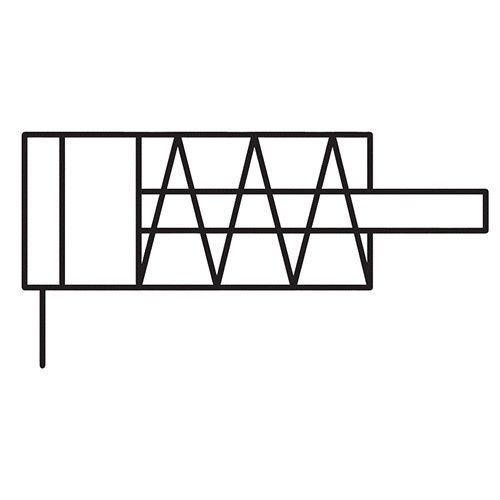
| What is a single acting cylinder? | • Single acting cylinders (SAC) use pneumatic pressure to create a force or linear motion that acts in one direction only. • A spring is used to return the cylinder to its original position |
| Draw the circuit symbol for a SAC. |
Image:
Sac (binary/octet-stream)
|
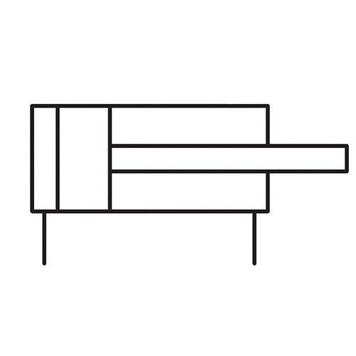
| What is a double acting cylinder? | • A double acting cylinder (DAC) can both extend and retract the cylinder using pressurized air (there is no spring return) • They can produce reciprocating motion |
| Draw the circuit symbol for a DAC. |
Image:
Dac (binary/octet-stream)
|
| How can a delay be created using pneumatics? | • 2 components are needed in series: o A unidirectional-flow control (fulfils the same function as a variable resistor in that it can increase or decrease air flow) o A reservoir (fulfils the same function as a capacitor in that it can store air) |
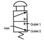
| What is a 3-port valve? | • A 3 port valve acts like a push to make switch • It allows air to pass only when it is activated |
| What does a 3-port valve look like? | |
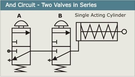
| =Design a pneumatic circuit that allows a SAC to operate only when 2 separate 3-port valves are activated at the same time (same function as an AND gate) | |
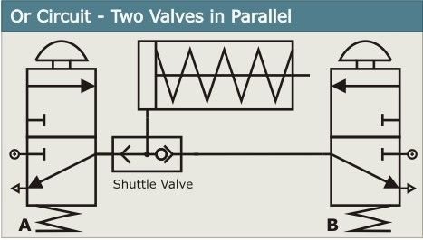
| What does a shuttle valve do? | • A shuttle valve joins 2 airflows into one. |
| Design a pneumatic circuit that allows a SAC to operate when any of 2 separate 3-port valves are activated (same function as an OR gate) – a shuttle valve will be needed | |
| When are pneumatic systems used? | • Where high speed and accuracy is required, e.g. controlling the movement of robotic arms • On automated assembly tools used in production lines • On power assisted construction tools, e.g. pneumatic drill |
Want to create your own Flashcards for free with GoConqr? Learn more.