
Flashcards
02Handout1
Cards in this deck (23)
- 1Electronics draftingis the process of illustrating various kinds of circuits and wiring systems
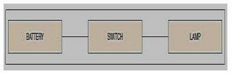
- 2Electronics Drawing DiagramsBlock Diagram
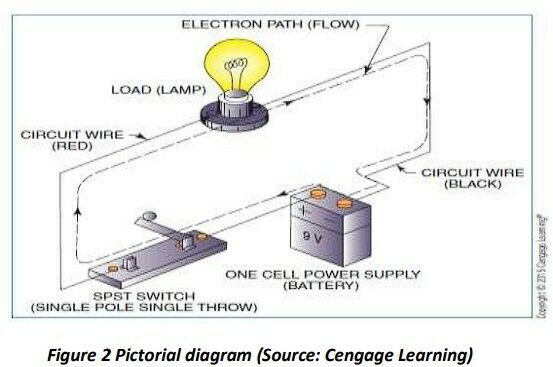
Pictorial Drawing
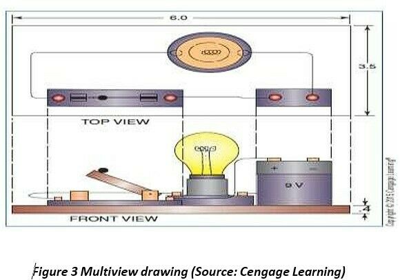
Multiview Drawing
Schematic Diagram - 3—Block diagram
- 4—Pictorial diagram
- 5—Multiview drawing diagram
- 6Electronic Industries Alliance (EIA) Military Standard (MIL STD) American Society of Mechanical Engineers International Electrotechnical Commission Institute of electrical and electronics engineers American National Standard InstituteElectronics Industry Standards

- 7—Electronics Drawing Symbols
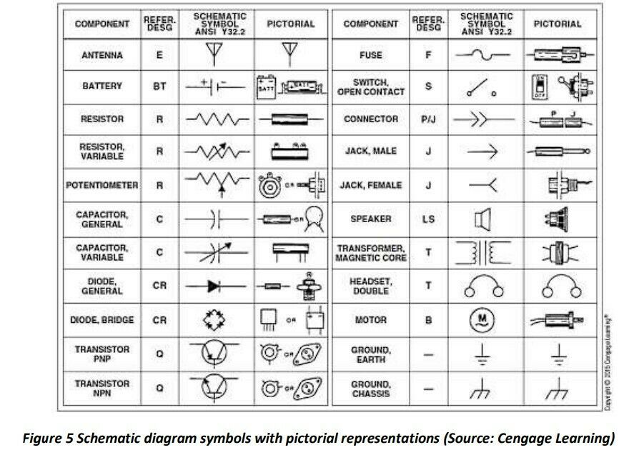
- 8sIn using electronic symbols to represent electronic circuit devices and components, use the following guidelines:
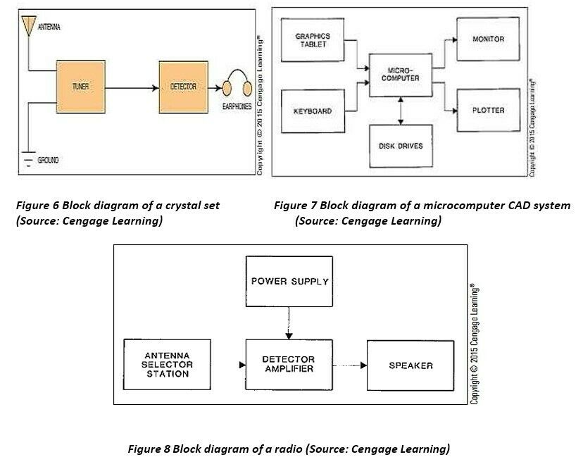
- 9Block diagramIt is a general representation drawing used to simplify and show the interrelationship of the various parts of an entire electronics system
- 10—Block diagram examples
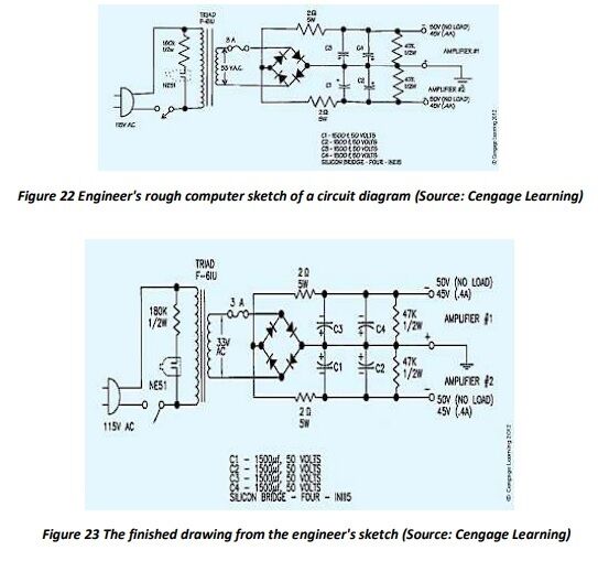
- 11Schematic diagramIt is the most frequently used drawings in the electronics industry.
- 12—Schematic diagram
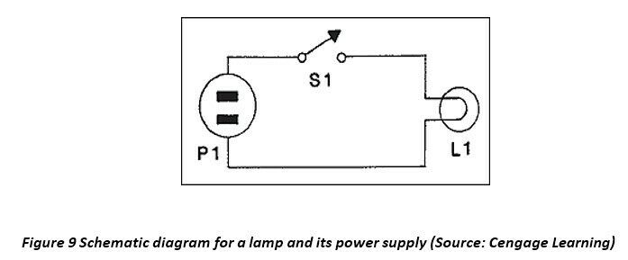
- 13Current flows from left to right, or upper left to lower right Allow space between symbols and connectors to avoid crowding Reference callouts are positioned in the same location, next to all symbols Keep the crossing of connector lines to a minimum If the scale is a factor, use grid overlay to avoid excessive dimensioningThe following are general rules for drawing schematic diagrams::
- 14Connection diagramsConnection or wiring diagrams are electronic assembly drawings that contain details needed to make or trace all electronic connections
- 15point-to-point highway or trunkline baseline or airline cableform diagramsTypes of connection diagrams
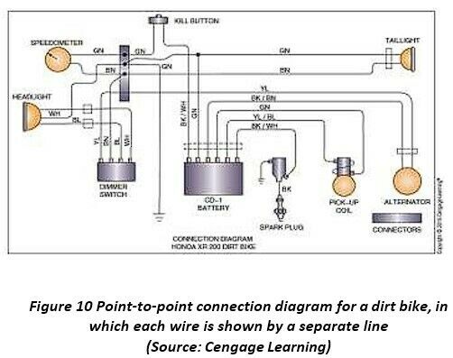
- 16Point-to-Point diagramsThese show components, drawn as simple outlines, with connecting lines and terminals
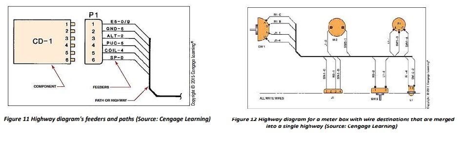
- 17Highway or trunkline diagramsthese are preferred when the addition of a large number of point-to-point interconnecting lines would be excessive
- 18Baseline or airline diagramsThe baseline diagram is a drawing shortcut procedure to allow the repositioning of components so the connectors can be shortened and drawn conveniently
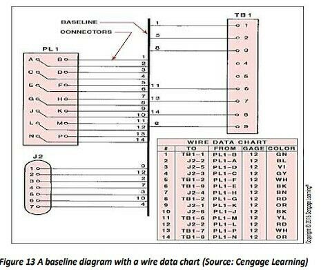
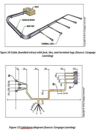
- 19Cableform diagram– It shows where each wire leaves the cable harness to make a connection
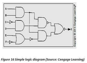
- 20Logic DiagramIt is used to design the microcircuitry used in many contemporary devices such as digital watches, calculators, and computers
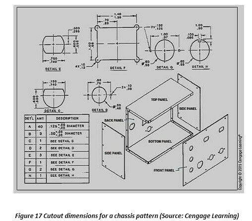
- 21Chassis drawingsThese are pattern or development drawings of cabinets that house electronic circuits and equipment
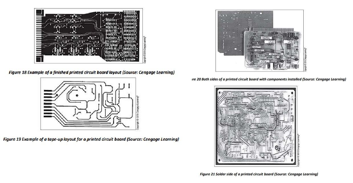
- 22Printed CircuitsThese are contemporary replacements for wired circuits
- 23Simplify drawing and electronic (and electrical) schematic diagrams Create CADD symbols that automatically prompt for and place the required text in drawing to define the symbolElectronics Drafting with CADD
Information
- Description
- normal Computer engineering Drafting and Design Flashcards on 02Handout1, created by Eljin Aguilar on 16/08/2024.
- Created by
- Eljin Aguilar · Aug 2024
- Updated
- Aug 16, 2024
- Views
- 1
- Rating